NISSAN LATIO 2009 Service Repair Manual
LATIO 2009
NISSAN
NISSAN
https://www.carmanualsonline.info/img/5/57359/w960_57359-0.png
NISSAN LATIO 2009 Service Repair Manual
Trending: wheel bolts, trip computer, open hood, coolant, fuel tank removal, keyless entry, jump start
Page 1181 of 4331
CVT
N
O P
Diagnosis Procedure
without CONSULT-III INFOID:0000000004305601
OBD-II SELF-DIAGNOSTIC PROCEDURE (WITH GST)
Refer to EC-1124, " Generic Scan Tool (GST) Function " .
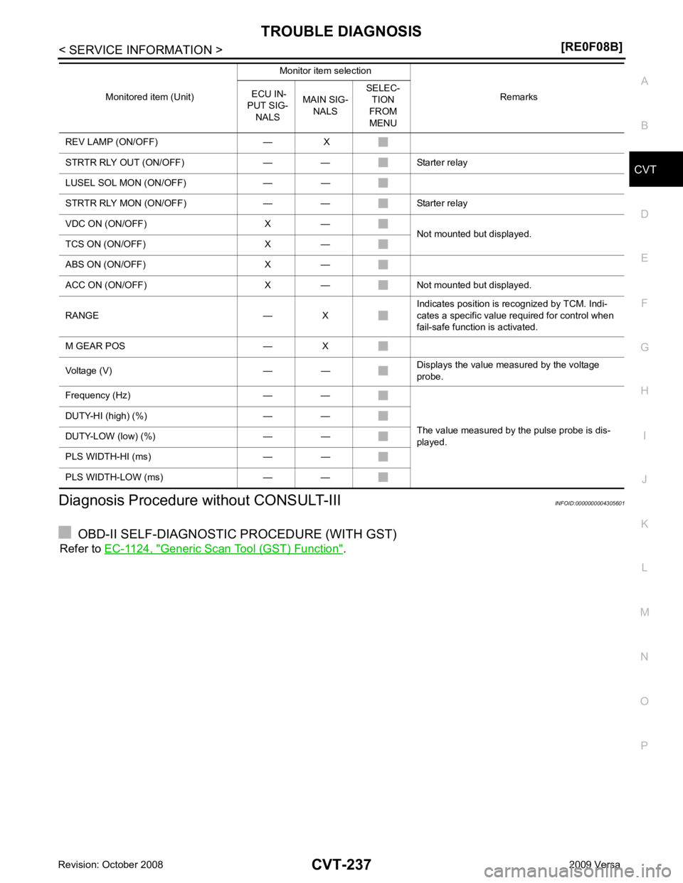
REV LAMP (ON/OFF) — X
STRTR RLY OUT (ON/OFF) — — Starter relay
LUSEL SOL MON (ON/OFF) — —
STRTR RLY MON (ON/OFF) — — Starter relay
VDC ON (ON/OFF) X — Not mounted but displayed.
TCS ON (ON/OFF) X —
ABS ON (ON/OFF) X —
ACC ON (ON/OFF) X — Not mounted but displayed.
RANGE — X Indicates position is recognized by TCM. Indi-
cates a specific value required for control when
fail-safe function is activated.
M GEAR POS — X
Voltage (V) — — Displays the value measured by the voltage
probe.
Frequency (Hz) — —
The value measured by the pulse probe is dis-
played.
DUTY-HI (high) (%) — —
DUTY-LOW (low) (%) — —
PLS WIDTH-HI (ms) — —
PLS WIDTH-LOW (ms) — — Monitored item (Unit)
Monitor item selection
Remarks
ECU IN-
PUT SIG- NALS MAIN SIG-
NALS SELEC-
TION
FROM
MENU
Page 1182 of 4331
Diagnosis Procedure " .
WITH GST
Follow the procedure “WITH CONSULT-III”.
Page 1183 of 4331
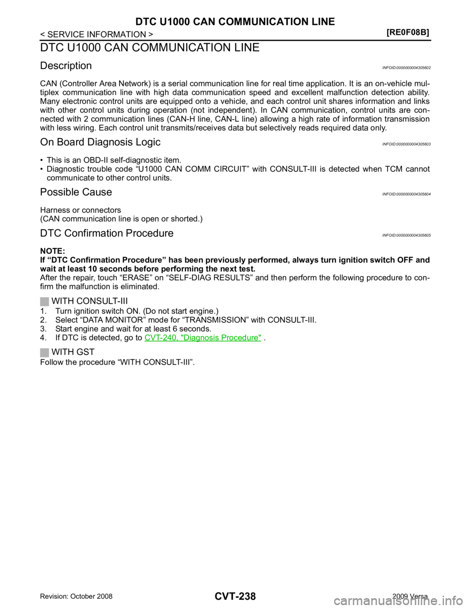
DTC U1000 CAN COMMUNICATION LINE
CVT-239
< SERVICE INFORMATION >
[RE0F08B] D
E
F
G H
I
J
K L
M A
B CVT
N
O P
Wiring Diagram - CVT - CAN
INFOID:0000000004305606
TCM TERMINALS AND REFERENCE VALUES Refer to CVT-228, " TCM Terminal and Reference Value " . BCWA0668E
Page 1184 of 4331
“ U1000 CAN COMM CIRCUIT ” indicated?
YES >> Print out CONSULT-III screen, go to LAN section. Refer to
LAN-26, " CAN System Specification
Chart " .
NO >> INSPECTION END
Page 1185 of 4331
CVT
N
O P
DTC U1010 TRANSMISSION
CONTROL MODULE (CAN)
Description INFOID:0000000004305608
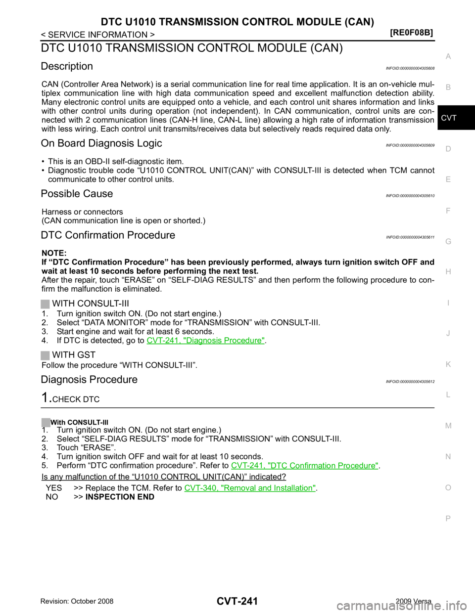
CAN (Controller Area Network) is a serial communication li ne for real time application. It is an on-vehicle mul-
tiplex communication line with high data communica tion speed and excellent malfunction detection ability.
Many electronic control units are equipped onto a vehicl e, and each control unit shares information and links
with other control units during operation (not independent ). In CAN communication, control units are con-
nected with 2 communication lines (CAN-H line, CAN-L li ne) allowing a high rate of information transmission
with less wiring. Each control unit transmits/recei ves data but selectively reads required data only.
On Board Diagnosis Logic INFOID:0000000004305609
• This is an OBD-II self-diagnostic item.
• Diagnostic trouble code “U1010 CONTROL UNIT(CAN)” with CONSULT-III is detected when TCM cannot
communicate to other control units.
Possible Cause INFOID:0000000004305610
Harness or connectors
(CAN communication line is open or shorted.)
DTC Confirmation Procedure INFOID:0000000004305611
NOTE:
If “DTC Confirmation Procedure” has been previously performed, alw ays turn ignition switch OFF and
wait at least 10 seconds before performing the next test.
After the repair, touch “ERASE” on “SELF-DIAG RESU LTS” and then perform the following procedure to con-
firm the malfunction is eliminated.
WITH CONSULT-III
1. Turn ignition switch ON. (Do not start engine.)
2. Select “DATA MONITOR” mode for “TRANSMISSION” with CONSULT-III.
3. Start engine and wait for at least 6 seconds.
4. If DTC is detected, go to CVT-241, " Diagnosis Procedure " .
WITH GST
Follow the procedure “WITH CONSULT-III”.
Diagnosis Procedure INFOID:0000000004305612DTC Confirmation Procedure " .
Is any malfunction of the “ U1010 CONTROL UNIT(CAN) ” indicated?
YES >> Replace the TCM. Refer to
CVT-340, " Removal and Installation " .
NO >> INSPECTION END
Page 1186 of 4331
Diagnosis Procedure " .
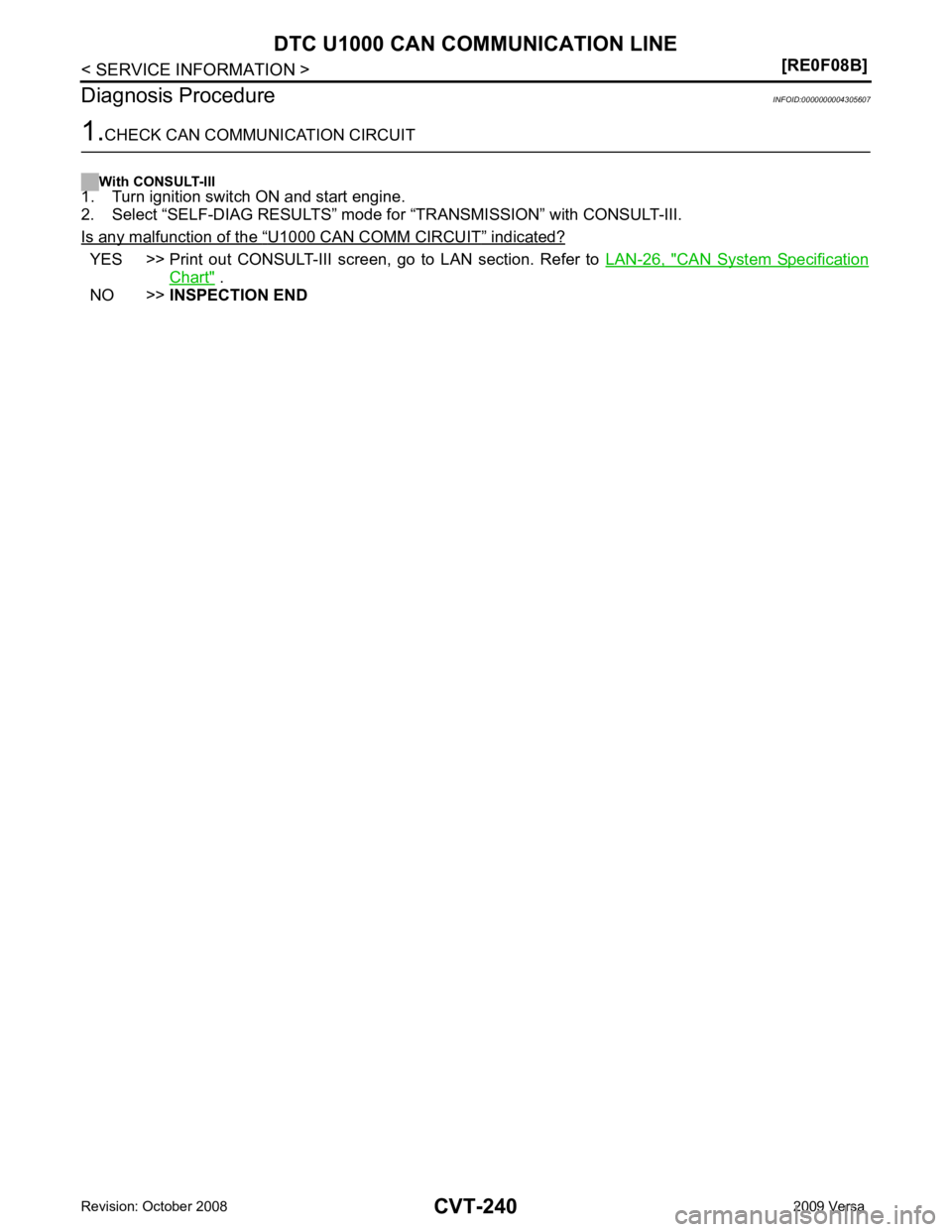
Diagnosis Procedure INFOID:0000000004305625CONSULT-III Function (TRANSMISSION) " .
Is any malfunction of the “ U1000 CAN COMM CIRCUIT ” indicated?
YES >> Check CAN communication line. Refer to
CVT-238 .
NO >> GO TO 2.
Page 1187 of 4331
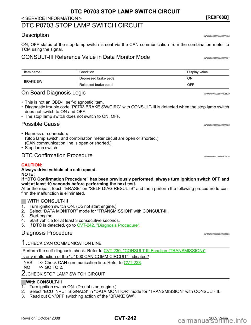
DTC P0703 STOP LAMP SWITCH CIRCUIT
CVT-243
< SERVICE INFORMATION >
[RE0F08B] D
E
F
G H
I
J
K L
M A
B CVT
N
O P
OK or NG OK >>
INSPECTION END
NG >> GO TO 3. 3.
CHECK STOP LAMP SWITCH
Check continuity between stop lamp switch harness connector E13
terminals 1 and 2. Refer to CVT-323, " Wiring Diagram - CVT - NON-
DTC " .
Check stop lamp switch after adjusting brake pedal — refer to
BR-6 .
OK or NG OK >> Check the following. If NG, repair or replace damaged parts.
• Harness for short or open between battery and stop lamp switch.
• Harness for short or open between stop lamp switch and combination meter.
NG >> Repair or replace the stop lamp switch.
Item name Condition Display value
BRAKE SW Depressed brake pedal ON
Released brake pedal OFF Condition Continuity
When brake pedal is depressed Yes
When brake pedal is released No SCIA7982E
Page 1188 of 4331
Diagnosis Procedure " .
WITH GST
Follow the procedure “WITH CONSULT-III”. Item name Condition Display value
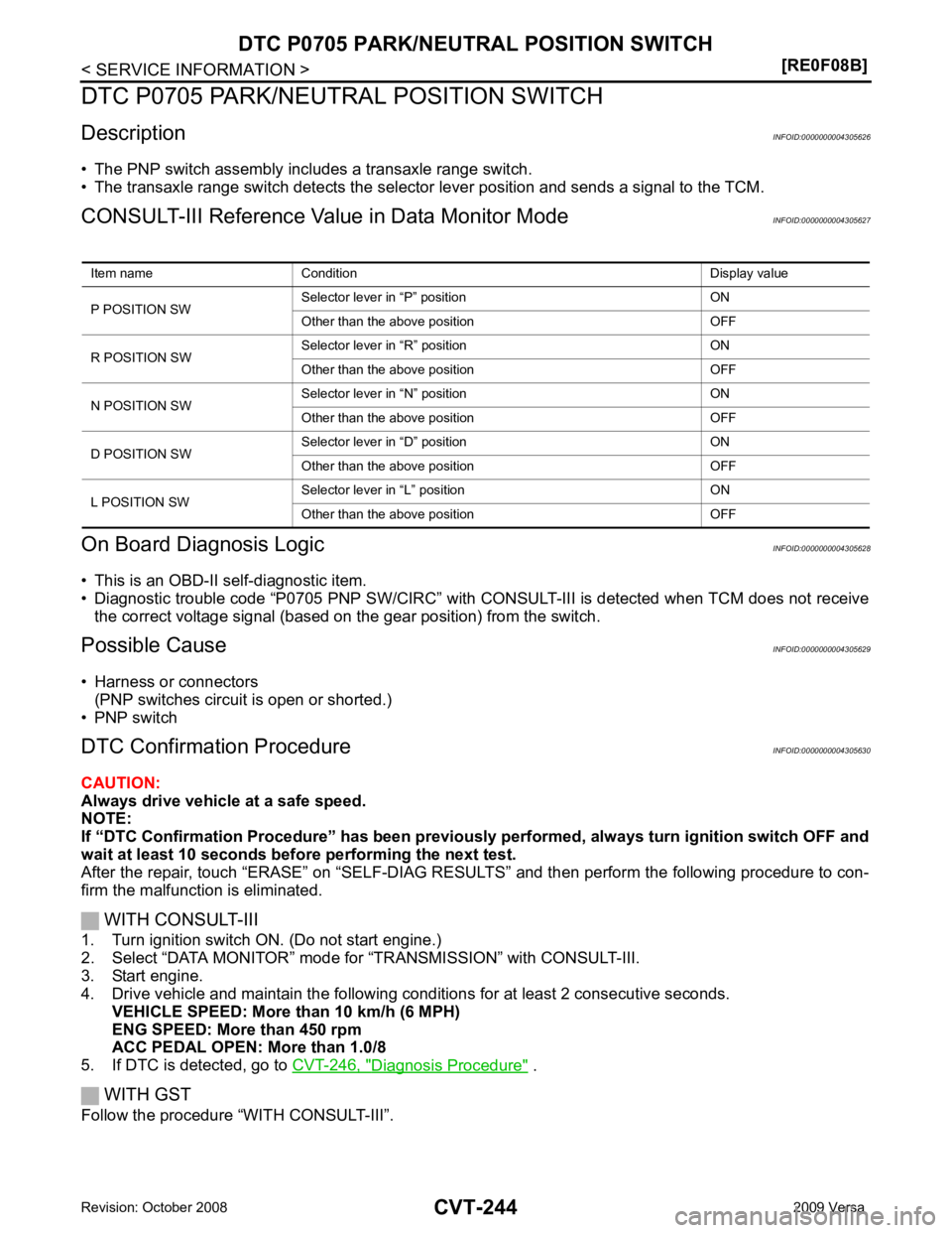
P POSITION SW Selector lever in “P” position ON
Other than the above position OFF
R POSITION SW Selector lever in “R” position ON
Other than the above position OFF
N POSITION SW Selector lever in “N” position ON
Other than the above position OFF
D POSITION SW Selector lever in “D” position ON
Other than the above position OFF
L POSITION SW Selector lever in “L” position ON
Other than the above position OFF
Page 1189 of 4331
CVT
N
O P
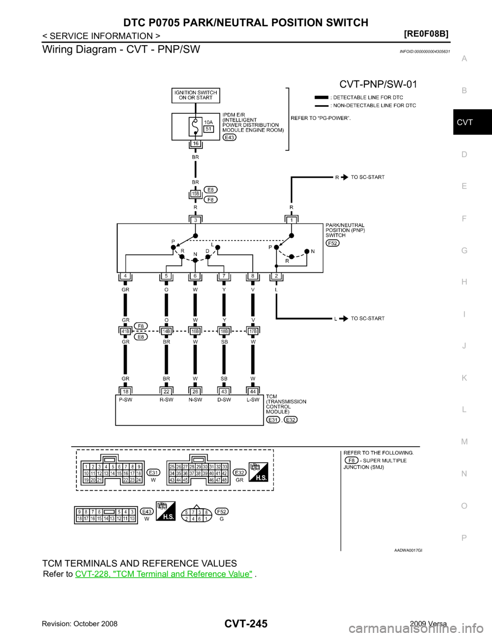
Wiring Diagram - CVT - PNP/SW
INFOID:0000000004305631
TCM TERMINALS AND REFERENCE VALUES Refer to CVT-228, " TCM Terminal and Reference Value " . B
Page 1190 of 4331
CONSULT-III
Reference Value in Data Monitor Mode " .
Without CONSULT-III
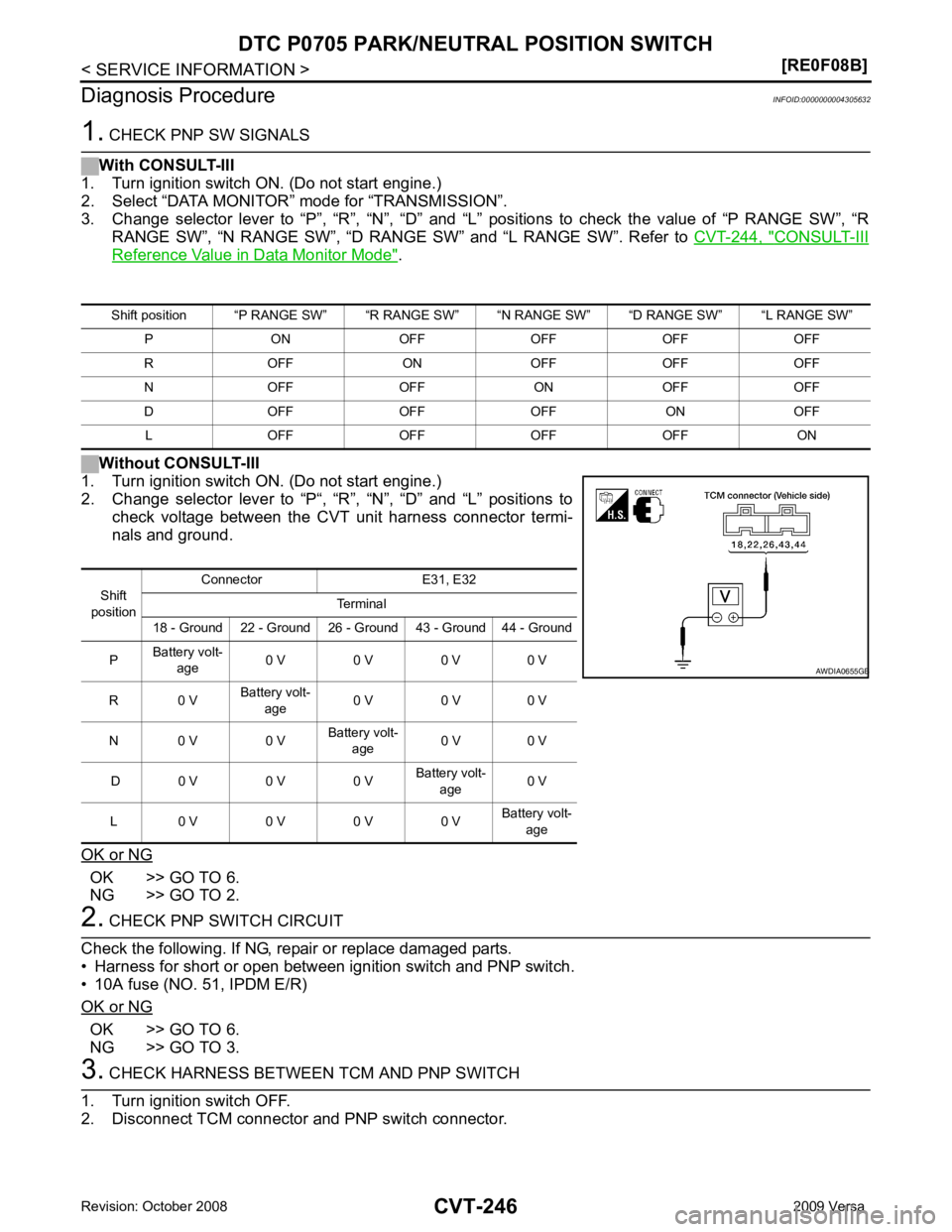
1. Turn ignition switch ON. (Do not start engine.)
2. Change selector lever to “P“, “R”, “N”, “D” and “L” positions to
check voltage between the CVT unit harness connector termi-
nals and ground.
OK or NG OK >> GO TO 6.
NG >> GO TO 2. OK >> GO TO 6.
NG >> GO TO 3. Shift
position Connector E31, E32
Terminal
18 - Ground 22 - Ground 26 - Ground 43 - Ground 44 - Ground
P Battery volt-
age 0 V 0 V 0 V 0 V
R 0 V Battery volt-
age 0 V 0 V 0 V
N 0 V 0 V Battery volt-
age 0 V 0 V
D 0 V 0 V 0 V Battery volt-
age 0 V
L 0 V 0 V 0 V 0 V Battery volt-
age B
Trending: fuel consumption, boot, cooling, bluetooth, inflation pressure, coolant temperature, compression ratio
![NISSAN LATIO 2009 Service Repair Manual DTC U1000 CAN COMMUNICATION LINE
CVT-239
< SERVICE INFORMATION >
[RE0F08B] D
E
F
G H
I
J
K L
M A
B CVT
N
O P
Wiring Diagram - CVT - CAN
INFOID:0000000004305606
TCM TERMINALS AND REFERENCE VALUES Refer NISSAN LATIO 2009 Service Repair Manual DTC U1000 CAN COMMUNICATION LINE
CVT-239
< SERVICE INFORMATION >
[RE0F08B] D
E
F
G H
I
J
K L
M A
B CVT
N
O P
Wiring Diagram - CVT - CAN
INFOID:0000000004305606
TCM TERMINALS AND REFERENCE VALUES Refer](/img/5/57359/w960_57359-1182.png)

![NISSAN LATIO 2009 Service Repair Manual DTC P0703 STOP LAMP SWITCH CIRCUIT
CVT-243
< SERVICE INFORMATION >
[RE0F08B] D
E
F
G H
I
J
K L
M A
B CVT
N
O P
OK or NG OK >>
INSPECTION END
NG >> GO TO 3. 3.
CHECK STOP LAMP SWITCH
Check continuity NISSAN LATIO 2009 Service Repair Manual DTC P0703 STOP LAMP SWITCH CIRCUIT
CVT-243
< SERVICE INFORMATION >
[RE0F08B] D
E
F
G H
I
J
K L
M A
B CVT
N
O P
OK or NG OK >>
INSPECTION END
NG >> GO TO 3. 3.
CHECK STOP LAMP SWITCH
Check continuity](/img/5/57359/w960_57359-1186.png)
