NISSAN LATIO 2009 Service Repair Manual
Manufacturer: NISSAN, Model Year: 2009, Model line: LATIO, Model: NISSAN LATIO 2009Pages: 4331, PDF Size: 58.04 MB
Page 1361 of 4331
EC
A
N
O P
Diagnosis Procedure ...........................................
..
349
P0507 ISC SYSTEM ....................................... ..351
Description .......................................................... ..351
DTC Logic ........................................................... ..351
Diagnosis Procedure ........................................... ..351
P0603 ECM POWER SUPPLY ....................... ..353
Description .......................................................... ..353
DTC Logic ........................................................... ..353
Diagnosis Procedure ........................................... ..353
P0605 ECM ..................................................... ..355
Description .......................................................... ..355
DTC Logic ........................................................... ..355
Diagnosis Procedure ........................................... ..356
P0607 ECM ..................................................... ..357
Description .......................................................... ..357
DTC Logic ........................................................... ..357
Diagnosis Procedure ........................................... ..357
P0643 SENSOR POWER SUPPLY ............... ..358
DTC Logic ........................................................... ..358
Wiring Diagram ................................................... ..359
Diagnosis Procedure ........................................... ..359
P0850 PNP SWITCH ...................................... ..362
Description .......................................................... ..362
DTC Logic ........................................................... ..362
Component Function Check ................................ ..363
Wiring Diagram ................................................... ..364
Diagnosis Procedure ........................................... ..364
P1148 CLOSED LOOP CONTROL ................ ..367
DTC Logic ........................................................... ..367
P1217 ENGINE OVER TEMPERATURE ....... ..368
DTC Logic ........................................................... ..368
Component Function Check ................................ ..368
Diagnosis Procedure ........................................... ..369
P1225 TP SENSOR ........................................ ..372
Description .......................................................... ..372
DTC Logic ........................................................... ..372
Diagnosis Procedure ........................................... ..372
Special Repair Requirem ent .................................373
P1226 TP SENSOR ........................................ ..374
Description .......................................................... ..374
DTC Logic ........................................................... ..374
Diagnosis Procedure ........................................... ..374
Special Repair Requirem ent .................................375
P1421 COLD START CONTROL ................... ..376
Description .......................................................... ..376
DTC Logic ........................................................... ..376
Diagnosis Procedure ........................................... ..376
P1715 INPUT SPEED SENSOR (PRIMARY
SPEED SENSOR) .......................................... ..
378
Description .......................................................... ..378 DTC Logic ............................................................
..378
Diagnosis Procedure ........................................... ..378
P1805 BRAKE SWITCH ................................. 380
Description ........................................................... ..380
DTC Logic ............................................................ ..380
Wiring Diagram .................................................... ..381
Diagnosis Procedure ........................................... ..381
Component Inspection (Stop Lamp Switch) ........ ..383
P2100, P2103 THROTTLE CONTROL MO-
TOR RELAY .................................................... 384
Description ........................................................... ..384
DTC Logic ............................................................ ..384
Wiring Diagram .................................................... ..385
Diagnosis Procedure ........................................... ..385
P2101 ELECTRIC THROTTLE CONTROL
FUNCTION ....... ............................................... 388
Description ........................................................... ..388
DTC Logic ............................................................ ..388
Wiring Diagram .................................................... ..389
Diagnosis Procedure ........................................... ..389
Component Inspection ......................................... ..392
Special Repair Requiremen t ..................................392
P2118 THROTTLE CONTROL MOTOR ......... 393
Description ........................................................... ..393
DTC Logic ............................................................ ..393
Wiring Diagram .................................................... ..394
Diagnosis Procedure ........................................... ..394
Component Inspection ......................................... ..395
Special Repair Requiremen t ..................................396
P2119 ELECTRIC THROTTLE CONTROL
ACTUATOR ..................................................... 397
Description ........................................................... ..397
DTC Logic ............................................................ ..397
Diagnosis Procedure ........................................... ..397
Special Repair Requiremen t ..................................398
P2122, P2123 APP SENSOR ......................... 399
Description ........................................................... ..399
DTC Logic ............................................................ ..399
Wiring Diagram .................................................... ..400
Diagnosis Procedure ........................................... ..400
Component Inspection ......................................... ..402
Special Repair Requiremen t ..................................402
P2127, P2128 APP SENSOR ......................... 403
Description ........................................................... ..403
DTC Logic ............................................................ ..403
Wiring Diagram .................................................... ..404
Diagnosis Procedure ........................................... ..404
Component Inspection ......................................... ..406
Special Repair Requiremen t ..................................407
P2135 TP SENSOR ......................................... 408
Description ........................................................... ..408
DTC Logic ............................................................ ..408
Page 1362 of 4331

Page 1363 of 4331
EC
A
N
O P
Inspection ............................................................
..
500
ON-VEHICLE REPAIR .... ...........................502
EVAP CANISTER ........................................... ..502
Exploded View .................................................... ..502
Removal and Installation .......................................502
Inspection ............................................................ ..503
SERVICE DATA AND SPECIFICATIONS
(SDS) ......... ................................. ................504
SERVICE DATA AND SPECIFICATIONS
(SDS) .............................................................. ..504
Idle Speed ........................................................... ..504
Ignition Timing ..................................................... ..504
Calculated Load Value ........................................ ..504
Mass Air Flow Sensor ......................................... ..504
MR TYPE 1
SERVICE INFOMATION .. ..........................505
APPLICATION NOTICE ................................. ..505
How to Check Vehicle Type ................................ ..505
INDEX FOR DTC ............................................ ..506
U1000-U1010 ...................................................... ..506
P0011-P0075 ...................................................... ..506
P0101-P0128 ...................................................... ..506
P0130-P0183 ...................................................... ..507
P0222-P0420 ...................................................... ..507
P0441-P0463 ...................................................... ..508
P0500-P0643 ...................................................... ..508
P0705-P0734 ...................................................... ..508
P0740-P0845 ...................................................... ..509
P0850-P1574 ...................................................... ..509
P1610-P1615 ...................................................... ..510
P1705-P1805 ...................................................... ..510
P2100-P2A00 ...................................................... ..510
PRECAUTIONS .............................................. ..512
Precaution for Supplemental Restraint System
(SRS) "AIR BAG" and "SEAT BELT PRE-TEN-
SIONER" ............................................................. ..
512
Precaution for Procedure without Cowl Top Cover ..512
On Board Diagnosis (OBD) System of Engine and
A/T, CVT ............................................................. ..
512
Precaution ........................................................... ..513
PREPARATION .............................................. ..516
Special Service Tool ........................................... ..516
Commercial Service Tool .................................... ..516
ENGINE CONTROL SYSTEM ........................ ..518
Schematic ........................................................... ..518
Multiport Fuel Injection (MFI) System ................. ..518
Electronic Ignition (EI) System ............................ ..521
Fuel Cut Control (at No Load and High Engine
Speed) ................................................................. ..
521
AIR CONDITIONING CUT CONTROL ........... ..523 Input/Output Signal Chart ....................................
..523
System Description .............................................. ..523
AUTOMATIC SPEED CONTROL DEVICE
(ASCD) ............................................................ 524
System Description .............................................. ..524
Component Description ....................................... ..525
CAN COMMUNICATION ................................. 526
System Description .............................................. ..526
EVAPORATIVE EMISSION SYSTEM ............. 527
Description ........................................................... ..527
Component Inspection ......................................... ..529
Removal and Installation ..................................... ..531
How to Detect Fuel Vapor Leakage ..................... ..531
ON BOARD REFUELING VAPOR RECOV-
ERY (ORVR) .................................................... 533
System Description .............................................. ..533
Diagnosis Procedure ........................................... ..533
Component Inspection ......................................... ..535
POSITIVE CRANKCASE VENTILATION ....... 538
Description ........................................................... ..538
Component Inspection ......................................... ..538
NVIS (NISSAN VEHICLE IMMOBILIZER SYS-
TEM-NATS) ..................................................... 540
Description ........................................................... ..540
ON BOARD DIAGNOSTIC (OBD) SYSTEM .. 541
Introduction .......................................................... ..541
Two Trip Detection Logic ..................................... ..541
Emission-related Diagnostic Information ............. ..542
Malfunction Indicator Lamp (MIL) ..........................557
OBD System Operation Chart ............................. ..560
BASIC SERVICE PROCEDURE ..................... 566
Basic Inspection .................................................. ..566
Idle Speed and Ignition Timing Check ................. ..570
Procedure After Replacing ECM ......................... ..571
VIN Registration .................................................. ..572
Accelerator Pedal Released Position Learning ... ..572
Throttle Valve Closed Position Learning ............. ..572
Idle Air Volume Learning ..................................... ..572
Fuel Pressure Check ........................................... ..574
TROUBLE DIAGNOSIS .................................. 577
Trouble Diagnosis Introduction ............................ ..577
DTC Inspection Priority Chart .............................. ..581
Fail-Safe Chart .................................................... ..582
Symptom Matrix Chart ......................................... ..583
Engine Control Component Parts Location ......... ..588
Vacuum Hose Drawing ........................................ ..594
Circuit Diagram .................................................... ..595
ECM Harness Connector Terminal Layout .......... ..597
ECM Terminal and Reference Value ................... ..597
CONSULT-III Function (ENGINE) ....................... ..604
Generic Scan Tool (GST) Function ..................... ..612
Page 1364 of 4331

Page 1365 of 4331
EC
A
N
O P
Component Description .......................................
..
679
CONSULT-III Refe rence Value in Data Monitor
Mode ................................................................... ..
679
On Board Diagnosis Logic .................................. ..679
DTC Confirmation Procedure .............................. ..679
Wiring Diagram ................................................... ..680
Diagnosis Procedure ........................................... ..681
Component Inspection ........................................ ..683
Removal and Installation .......................................683
DTC P0125 ECT SENSOR ............................. ..684
Description .......................................................... ..684
On Board Diagnosis Logic .................................. ..684
DTC Confirmation Procedure .............................. ..684
Diagnosis Procedure ........................................... ..685
Component Inspection ........................................ ..686
Removal and Installation .......................................686
DTC P0127 IAT SENSOR .............................. ..687
Component Description ....................................... ..687
On Board Diagnosis Logic .................................. ..687
DTC Confirmation Procedure .............................. ..687
Diagnosis Procedure ........................................... ..688
Component Inspection ........................................ ..688
Removal and Installation .......................................689
DTC P0128 THERMOSTAT FUNCTION ........ ..690
On Board Diagnosis Logic .................................. ..690
DTC Confirmation Procedure .............................. ..690
Diagnosis Procedure ........................................... ..690
Component Inspection ........................................ ..691
Removal and Installation .......................................691
DTC P0130 A/F SENSOR 1 ........................... ..692
Component Description ....................................... ..692
CONSULT-III Refe rence Value in Data Monitor
Mode ................................................................... ..
692
On Board Diagnosis Logic .................................. ..692
DTC Confirmation Procedure .............................. ..692
Overall Function Check ....................................... ..693
Wiring Diagram ................................................... ..694
Diagnosis Procedure ........................................... ..695
Removal and Installation .......................................697
DTC P0131 A/F SENSOR 1 ........................... ..698
Component Description ....................................... ..698
CONSULT-III Refe rence Value in Data Monitor
Mode ................................................................... ..
698
On Board Diagnosis Logic .................................. ..698
DTC Confirmation Procedure .............................. ..698
Wiring Diagram ................................................... ..700
Diagnosis Procedure ........................................... ..701
Removal and Installation .......................................703
DTC P0132 A/F SENSOR 1 ........................... ..704
Component Description ....................................... ..704
CONSULT-III Refe rence Value in Data Monitor
Mode ................................................................... ..
704
On Board Diagnosis Logic .................................. ..704
DTC Confirmation Procedure .............................. ..704 Wiring Diagram ....................................................
..706
Diagnosis Procedure ........................................... ..707
Removal and Installation ..................................... ..709
DTC P0133 A/F SENSOR 1 ............................ 710
Component Description ....................................... ..710
CONSULT-III Reference Va lue in Data Monitor
Mode .................................................................... ..
710
On Board Diagnosis Logic ................................... ..710
DTC Confirmation Procedure .............................. ..710
Wiring Diagram .................................................... ..712
Diagnosis Procedure ........................................... ..713
Removal and Installation ..................................... ..716
DTC P0137 HO2S2 ......................................... 717
Component Description ....................................... ..717
CONSULT-III Reference Va lue in Data Monitor
Mode .................................................................... ..
717
On Board Diagnosis Logic ................................... ..717
DTC Confirmation Procedure .............................. ..717
Overall Function Check ....................................... ..718
Wiring Diagram .................................................... ..719
Diagnosis Procedure ........................................... ..720
Component Inspection ......................................... ..722
Removal and Installation ..................................... ..723
DTC P0138 HO2S2 ......................................... 724
Component Description ....................................... ..724
CONSULT-III Reference Va lue in Data Monitor
Mode .................................................................... ..
724
On Board Diagnosis Logic ................................... ..724
DTC Confirmation Procedure .............................. ..725
Overall Function Check ....................................... ..725
Wiring Diagram .................................................... ..727
Diagnosis Procedure ........................................... ..728
Component Inspection ......................................... ..731
Removal and Installation ..................................... ..732
DTC P0139 HO2S2 ......................................... 733
Component Description ....................................... ..733
CONSULT-III Reference Va lue in Data Monitor
Mode .................................................................... ..
733
On Board Diagnosis Logic ................................... ..733
DTC Confirmation Procedure .............................. ..733
Overall Function Check ....................................... ..734
Wiring Diagram .................................................... ..735
Diagnosis Procedure ........................................... ..736
Component Inspection ......................................... ..738
Removal and Installation ..................................... ..739
DTC P0171 FUEL INJECTION SYSTEM
FUNCTION ....... ...............................................
740
On Board Diagnosis Logic ................................... ..740
DTC Confirmation Procedure .............................. ..740
Wiring Diagram .................................................... ..742
Diagnosis Procedure ........................................... ..743
DTC P0172 FUEL INJECTION SYSTEM
FUNCTION ....... ............................................... 746
On Board Diagnosis Logic ...................................
Page 1366 of 4331

Page 1367 of 4331
EC
A
N
O P
Wiring Diagram ...................................................
..
818
Diagnosis Procedure ........................................... ..819
Component Inspection ........................................ ..821
DTC P0448 EVAP CANISTER VENT CON-
TROL VALVE ................................................. ..823
Component Description ....................................... ..823
CONSULT-III Refe rence Value in Data Monitor
Mode ................................................................... ..
823
On Board Diagnosis Logic .................................. ..823
DTC Confirmation Procedure .............................. ..823
Wiring Diagram ................................................... ..825
Diagnosis Procedure ........................................... ..826
Component Inspection ........................................ ..827
DTC P0451 EVAP CONTROL SYSTEM
PRESSURE SENSO R .................................... ..829
Component Description ....................................... ..829
CONSULT-III Refe rence Value in Data Monitor
Mode ................................................................... ..
829
On Board Diagnosis Logic .................................. ..829
DTC Confirmation Procedure .............................. ..829
Diagnosis Procedure ........................................... ..830
Component Inspection ........................................ ..831
DTC P0452 EVAP CONTROL SYSTEM
PRESSURE SENSO R .................................... ..
832
Component Description ....................................... ..832
CONSULT-III Refe rence Value in Data Monitor
Mode ................................................................... ..
832
On Board Diagnosis Logic .................................. ..832
DTC Confirmation Procedure .............................. ..832
Wiring Diagram ................................................... ..834
Diagnosis Procedure ........................................... ..835
Component Inspection ........................................ ..838
DTC P0453 EVAP CONTROL SYSTEM
PRESSURE SENSO R .................................... ..839
Component Description ....................................... ..839
CONSULT-III Refe rence Value in Data Monitor
Mode ................................................................... ..
839
On Board Diagnosis Logic .................................. ..839
DTC Confirmation Procedure .............................. ..839
Wiring Diagram ................................................... ..841
Diagnosis Procedure ........................................... ..842
Component Inspection ........................................ ..846
DTC P0455 EVAP CONTROL SYSTEM ........ ..847
On Board Diagnosis Logic .................................. ..847
DTC Confirmation Procedure .............................. ..847
Diagnosis Procedure ........................................... ..848
DTC P0456 EVAP CONTROL SYSTEM ........ ..853
On Board Diagnosis Logic .................................. ..853
DTC Confirmation Procedure .............................. ..854
Overall Function Check ....................................... ..854
Diagnosis Procedure ........................................... ..855
DTC P0460 FUEL LEVEL SENSOR .............. ..860
Component Description ....................................... ..860 On Board Diagnosis Logic ...................................
..860
DTC Confirmation Procedure .............................. ..860
Diagnosis Procedure ........................................... ..860
Removal and Installation ..................................... ..861
DTC P0461 FUEL LEVEL SENSOR ............... 862
Component Description ....................................... ..862
On Board Diagnosis Logic ................................... ..862
Overall Function Check ....................................... ..862
Diagnosis Procedure ........................................... ..863
Removal and Installation ..................................... ..863
DTC P0462, P0463 FUEL LEVEL SENSOR .. 864
Component Description ....................................... ..864
On Board Diagnosis Logic ................................... ..864
DTC Confirmation Procedure .............................. ..864
Diagnosis Procedure ........................................... ..864
Removal and Installation ..................................... ..865
DTC P0500 VSS .............................................. 866
Description ........................................................... ..866
On Board Diagnosis Logic ................................... ..866
DTC Confirmation Procedure .............................. ..866
Overall Function Check ....................................... ..867
Diagnosis Procedure ........................................... ..867
DTC P0506 ISC SYSTEM ............................... 868
Description ........................................................... ..868
On Board Diagnosis Logic ................................... ..868
DTC Confirmation Procedure .............................. ..868
Diagnosis Procedure ........................................... ..868
DTC P0507 ISC SYSTEM ............................... 870
Description ........................................................... ..870
On Board Diagnosis Logic ................................... ..870
DTC Confirmation Procedure .............................. ..870
Diagnosis Procedure ........................................... ..870
DTC P0605 ECM ............................................. 872
Component Description ....................................... ..872
On Board Diagnosis Logic ................................... ..872
DTC Confirmation Procedure .............................. ..872
Diagnosis Procedure ........................................... ..873
DTC P0643 SENSOR POWER SUPPLY ........ 874
On Board Diagnosis Logic ................................... ..874
DTC Confirmation Procedure .............................. ..874
Wiring Diagram .................................................... ..875
Diagnosis Procedure ........................................... ..876
DTC P0850 PNP SWITCH .............................. 879
Component Description ....................................... ..879
CONSULT-III Reference Va lue in Data Monitor
Mode .................................................................... ..
879
On Board Diagnosis Logic ................................... ..879
DTC Confirmation Procedure .............................. ..879
Overall Function Check ....................................... ..880
Wiring Diagram .................................................... ..881
Diagnosis Procedure ........................................... ..882
DTC P1148 CLOSED LOOP CONTROL ........ 885
Page 1368 of 4331

Page 1369 of 4331
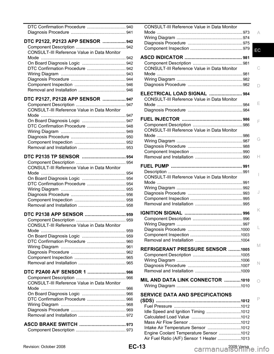
EC
A
N
O P
DTC Confirmation Procedure ..............................
..
940
Diagnosis Procedure ........................................... ..941
DTC P2122, P2123 APP SENSOR ................ ..942
Component Description ....................................... ..942
CONSULT-III Refe rence Value in Data Monitor
Mode ................................................................... ..
942
On Board Diagnosis Logic .................................. ..942
DTC Confirmation Procedure .............................. ..942
Wiring Diagram ................................................... ..943
Diagnosis Procedure ........................................... ..944
Component Inspection ........................................ ..946
Removal and Installation .......................................946
DTC P2127, P2128 APP SENSOR ................ ..947
Component Description ....................................... ..947
CONSULT-III Refe rence Value in Data Monitor
Mode ................................................................... ..
947
On Board Diagnosis Logic .................................. ..947
DTC Confirmation Procedure .............................. ..948
Wiring Diagram ................................................... ..949
Diagnosis Procedure ........................................... ..950
Component Inspection ........................................ ..952
Removal and Installation .......................................953
DTC P2135 TP SENSOR ............................... ..954
Component Description ....................................... ..954
CONSULT-III Refe rence Value in Data Monitor
Mode ................................................................... ..
954
On Board Diagnosis Logic .................................. ..954
DTC Confirmation Procedure .............................. ..954
Wiring Diagram ................................................... ..955
Diagnosis Procedure ........................................... ..956
Component Inspection ........................................ ..958
Removal and Installation .......................................958
DTC P2138 APP SENSOR ............................. ..959
Component Description ....................................... ..959
CONSULT-III Refe rence Value in Data Monitor
Mode ................................................................... ..
959
On Board Diagnosis Logic .................................. ..959
DTC Confirmation Procedure .............................. ..960
Wiring Diagram ................................................... ..961
Diagnosis Procedure ........................................... ..962
Component Inspection ........................................ ..965
Removal and Installation .......................................965
DTC P2A00 A/F SENSOR 1 ........................... ..966
Component Description ....................................... ..966
CONSULT-III Refe rence Value in Data Monitor
Mode ................................................................... ..
966
On Board Diagnosis Logic .................................. ..966
DTC Confirmation Procedure .............................. ..966
Wiring Diagram ................................................... ..968
Diagnosis Procedure ........................................... ..969
Removal and Installation .......................................972
ASCD BRAKE SWITCH ................................. ..973
Component Description ....................................... ..973 CONSULT-III Reference Va
lue in Data Monitor
Mode .................................................................... ..
973
Wiring Diagram .................................................... ..974
Diagnosis Procedure ........................................... ..975
Component Inspection ......................................... ..979
ASCD INDICATOR .......................................... 981
Component Description ....................................... ..981
CONSULT-III Reference Va lue in Data Monitor
Mode .................................................................... ..
981
Wiring Diagram .................................................... ..982
Diagnosis Procedure ........................................... ..982
ELECTRICAL LOAD SIGNAL ........................ 984
CONSULT-III Reference Va lue in Data Monitor
Mode .................................................................... ..
984
Diagnosis Procedure ........................................... ..984
FUEL INJECTOR ............................................ 986
Component Description ....................................... ..986
CONSULT-III Reference Va lue in Data Monitor
Mode .................................................................... ..
986
Wiring Diagram .................................................... ..987
Diagnosis Procedure ........................................... ..988
Component Inspection ......................................... ..990
Removal and Installation ..................................... ..990
FUEL PUMP .................................................... 991
Description ........................................................... ..991
CONSULT-III Reference Va lue in Data Monitor
Mode .................................................................... ..
991
Wiring Diagram .................................................... ..992
Diagnosis Procedure ........................................... ..993
Component Inspection ......................................... ..995
Removal and Installation ..................................... ..995
IGNITION SIGNAL .......................................... 996
Component Description ....................................... ..996
Wiring Diagram .................................................... ..997
Diagnosis Procedure ........................................... 1000
Component Inspection ......................................... 1003
Removal and Installation ..................................... 1004
REFRIGERANT PRESSURE SENSOR ......... 1005
Component Description ....................................... 1005
Wiring Diagram .................................................... 1006
Diagnosis Procedure ........................................... 1007
Removal and Installation ..................................... 1009
MIL AND DATA LINK CONNECTOR ............ 1010
Wiring Diagram .................................................... 1010
SERVICE DATA AND SPECIFICATIONS
(SDS) .............................................................. 1012
Fuel Pressure ...................................................... 1012
Idle Speed and Ignition Timing ............................ 1012
Calculated Load Value ........................................ 1012
Mass Air Flow Sensor .......................................... 1012
Intake Air Temperature Sensor ........................... 1012
Engine Coolant Temperature Sensor .................. 1012
Air Fuel Ratio (A/F) Sensor 1 Heater ................... 1013
Page 1370 of 4331
