NISSAN LATIO 2009 Service Repair Manual
Manufacturer: NISSAN, Model Year: 2009, Model line: LATIO, Model: NISSAN LATIO 2009Pages: 4331, PDF Size: 58.04 MB
Page 1371 of 4331

EC
A
N
O P
Description ..........................................................
1138
Diagnosis Procedure ........................................... 1138
POWER SUPPLY AND GROUND CIRCUIT .. 1139
Wiring Diagram ................................................... 1139
Diagnosis Procedure ........................................... 1140
Ground Inspection ............................................... 1144
DTC U0101 CAN COMMUNICATION LINE ... 1145
Description .......................................................... 1145
On Board Diagnosis Logic .................................. 1145
DTC Confirmation Procedure .............................. 1145
Wiring Diagram ................................................... 1146
Diagnosis Procedure ........................................... 1146
DTC U0140 CAN COMMUNICATION LINE ... 1147
Description .......................................................... 1147
On Board Diagnosis Logic .................................. 1147
DTC Confirmation Procedure .............................. 1147
Wiring Diagram ................................................... 1148
Diagnosis Procedure ........................................... 1148
DTC U1001 CAN COMMUNICATION LINE ... 1149
Description .......................................................... 1149
On Board Diagnosis Logic .................................. 1149
DTC Confirmation Procedure .............................. 1149
Wiring Diagram ................................................... 1150
Diagnosis Procedure ........................................... 1150
DTC P0011 IVT CONTROL ............................ 1151
Description .......................................................... 1151
CONSULT-III Refe rence Value in Data Monitor
Mode ................................................................... 1151
On Board Diagnosis Logic .................................. 1152
DTC Confirmation Procedure .............................. 1152
Diagnosis Procedure ........................................... 1153
Component Inspection ........................................ 1154
Removal and Installation .....................................1154
DTC P0031, P0032 A/F SENSOR 1 HEATER 1155
Description .......................................................... 1155
CONSULT-III Refe rence Value in Data Monitor
Mode ................................................................... 1155
On Board Diagnosis Logic .................................. 1155
DTC Confirmation Procedure .............................. 1155
Wiring Diagram ................................................... 1156
Diagnosis Procedure ........................................... 1157
Component Inspection ........................................ 1158
Removal and Installation .....................................1159
DTC P0037, P0038 HO2S2 HEATER ............ 1160
Description .......................................................... 1160
CONSULT-III Refe rence Value in Data Monitor
Mode ................................................................... 1160
On Board Diagnosis Logic .................................. 1160
DTC Confirmation Procedure .............................. 1160
Wiring Diagram ................................................... 1161
Diagnosis Procedure ........................................... 1162
Component Inspection ........................................ 1164
Removal and Installation .....................................1164DTC P0075 IVT CONTROL SOLENOID
VALVE ............................................................ 1165
Component Description ....................................... 1165
CONSULT-III Reference Va lue in Data Monitor
Mode .................................................................... 1165
On Board Diagnosis Logic ................................... 1165
DTC Confirmation Procedure .............................. 1165
Wiring Diagram .................................................... 1166
Diagnosis Procedure ........................................... 1167
Component Inspection ......................................... 1168
Removal and Installation ..................................... 1169
DTC P0101 MAF SENSOR ............................ 1170
Component Description ....................................... 1170
CONSULT-III Reference Va lue in Data Monitor
Mode .................................................................... 1170
On Board Diagnosis Logic ................................... 1170
DTC Confirmation Procedure .............................. 1170
Overall Function Check ....................................... 1171
Wiring Diagram .................................................... 1173
Diagnosis Procedure ........................................... 1174
Component Inspection ......................................... 1176
Removal and Installation ..................................... 1177
DTC P0102, P0103 MAF SENSOR ................ 1178
Component Description ....................................... 1178
CONSULT-III Reference Va lue in Data Monitor
Mode .................................................................... 1178
On Board Diagnosis Logic ................................... 1178
DTC Confirmation Procedure .............................. 1178
Wiring Diagram .................................................... 1180
Diagnosis Procedure ........................................... 1181
Component Inspection ......................................... 1183
Removal and Installation ..................................... 1184
DTC P0112, P0113 IAT SENSOR .................. 1185
Component Description ....................................... 1185
On Board Diagnosis Logic ................................... 1185
DTC Confirmation Procedure .............................. 1185
Wiring Diagram .................................................... 1186
Diagnosis Procedure ........................................... 1186
Component Inspection ......................................... 1188
Removal and Installation ..................................... 1188
DTC P0116 ECT SENSOR ............................. 1189
Component Description ....................................... 1189
On Board Diagnosis Logic ................................... 1189
DTC Confirmation Procedure .............................. 1189
Diagnosis Procedure ........................................... 1190
Component Inspection ......................................... 1190
Removal and Installation ..................................... 1191
DTC P0117, P0118 ECT SENSOR ................ 1192
Component Description ....................................... 1192
On Board Diagnosis Logic ................................... 1192
DTC Confirmation Procedure .............................. 1193
Wiring Diagram .................................................... 1194
Diagnosis Procedure ........................................... 1194
Component Inspection ......................................... 1196
Removal and Installation ..................................... 1196
Page 1372 of 4331

Page 1373 of 4331

EC
A
N
O P
On Board Diagnosis Logic ..................................
1264
DTC Confirmation Procedure .............................. 1264
Wiring Diagram ................................................... 1266
Diagnosis Procedure ........................................... 1267
DTC P0181 FTT SENSOR ............................. 1270
Component Description ....................................... 1270
On Board Diagnosis Logic .................................. 1270
DTC Confirmation Procedure .............................. 1270
Wiring Diagram ................................................... 1271
Diagnosis Procedure ........................................... 1271
Component Inspection ........................................ 1273
Removal and Installation .....................................1273
DTC P0182, P0183 FTT SENSOR ................. 1274
Component Description ....................................... 1274
On Board Diagnosis Logic .................................. 1274
DTC Confirmation Procedure .............................. 1274
Wiring Diagram ................................................... 1275
Diagnosis Procedure ........................................... 1275
Component Inspection ........................................ 1277
Removal and Installation .....................................1277
DTC P0222, P0223 TP SENSOR ................... 1278
Component Description ....................................... 1278
CONSULT-III Refe rence Value in Data Monitor
Mode ................................................................... 1278
On Board Diagnosis Logic .................................. 1278
DTC Confirmation Procedure .............................. 1278
Wiring Diagram ................................................... 1279
Diagnosis Procedure ........................................... 1280
Component Inspection ........................................ 1282
Removal and Installation .....................................1282
DTC P0300 - P0304 MULTIPLE CYLINDER
MISFIRE, NO. 1 - 4 CYLINDER MISFIRE ...... 1283
On Board Diagnosis Logic .................................. 1283
DTC Confirmation Procedure .............................. 1283
Diagnosis Procedure ........................................... 1284
DTC P0327, P0328 KS ................................... 1289
Component Description ....................................... 1289
On Board Diagnosis Logic .................................. 1289
DTC Confirmation Procedure .............................. 1289
Wiring Diagram ................................................... 1290
Diagnosis Procedure ........................................... 1291
Component Inspection ........................................ 1292
Removal and Installation .....................................1292
DTC P0335 CKP SENSOR (POS) ................. 1293
Component Description ....................................... 1293
CONSULT-III Refe rence Value in Data Monitor
Mode ................................................................... 1293
On Board Diagnosis Logic .................................. 1293
DTC Confirmation Procedure .............................. 1293
Wiring Diagram ................................................... 1294
Diagnosis Procedure ........................................... 1295
Component Inspection ........................................ 1298
Removal and Installation .....................................1298DTC P0340 CMP SENSOR (PHASE) ............
1299
Component Description ....................................... 1299
CONSULT-III Reference Va lue in Data Monitor
Mode .................................................................... 1299
On Board Diagnosis Logic ................................... 1299
DTC Confirmation Procedure .............................. 1299
Wiring Diagram .................................................... 1300
Diagnosis Procedure ........................................... 1301
Component Inspection ......................................... 1303
Removal and Installation ..................................... 1304
DTC P0420 THREE WAY CATALYST FUNC-
TION ............................................................... 1305
On Board Diagnosis Logic ................................... 1305
DTC Confirmation Procedure .............................. 1305
Overall Function Check ....................................... 1305
Diagnosis Procedure ........................................... 1306
DTC P0441 EVAP CONTROL SYSTEM ........ 1310
System Description .............................................. 1310
On Board Diagnosis Logic ................................... 1310
DTC Confirmation Procedure .............................. 1310
Overall Function Check ....................................... 1311
Diagnosis Procedure ........................................... 1311
Component Inspection ......................................... 1314
DTC P0442 EVAP CONTROL SYSTEM ........ 1315
On Board Diagnosis Logic ................................... 1315
DTC Confirmation Procedure .............................. 1316
Diagnosis Procedure ........................................... 1316
Component Inspection ......................................... 1321
DTC P0443 EVAP CANISTER PURGE VOL-
UME CONTROL SOLENOID VALVE ............ 1322
Description ........................................................... 1322
CONSULT-III Reference Va lue in Data Monitor
Mode .................................................................... 1322
On Board Diagnosis Logic ................................... 1323
DTC Confirmation Procedure .............................. 1323
Wiring Diagram .................................................... 1325
Diagnosis Procedure ........................................... 1326
Component Inspection ......................................... 1329
Removal and Installation ..................................... 1329
DTC P0444, P0445 EVAP CANISTER PURGE
VOLUME CONTROL SOLENOID VALVE ..... 1330
Description ........................................................... 1330
CONSULT-III Reference Va lue in Data Monitor
Mode .................................................................... 1330
On Board Diagnosis Logic ................................... 1331
DTC Confirmation Procedure .............................. 1331
Wiring Diagram .................................................... 1332
Diagnosis Procedure ........................................... 1333
Component Inspection ......................................... 1334
Removal and Installation ..................................... 1335
DTC P0447 EVAP CANISTER VENT CON-
TROL VALVE ................................................. 1336
Component Description ....................................... 1336
Page 1374 of 4331

Page 1375 of 4331

EC
A
N
O P
DTC P0850 PNP SWITCH ..............................
1401
Component Description ....................................... 1401
CONSULT-III Refe rence Value in Data Monitor
Mode ................................................................... 1401
On Board Diagnosis Logic .................................. 1401
DTC Confirmation Procedure .............................. 1401
Overall Function Check ....................................... 1402
Wiring Diagram ................................................... 1403
Diagnosis Procedure ........................................... 1404
DTC P1148 CLOSED LOOP CONTROL ....... 1407
On Board Diagnosis Logic .................................. 1407
DTC P1217 ENGINE OVER TEMPERATURE 1408
System Description ............................................. 1408
CONSULT-III Refe rence Value in Data Monitor
Mode ................................................................... 1409
On Board Diagnosis Logic .................................. 1409
Overall Function Check ....................................... 1409
Wiring Diagram ................................................... 1411
Diagnosis Procedure ........................................... 1412
Main 13 Causes of Overheating .......................... 1415
Component Inspection ........................................ 1416
DTC P1225 TP SENSOR ............................... 1417
Component Description ....................................... 1417
On Board Diagnosis Logic .................................. 1417
DTC Confirmation Procedure .............................. 1417
Diagnosis Procedure ........................................... 1417
Removal and Installation .....................................1418
DTC P1226 TP SENSOR ............................... 1419
Component Description ....................................... 1419
On Board Diagnosis Logic .................................. 1419
DTC Confirmation Procedure .............................. 1419
Diagnosis Procedure ........................................... 1419
Removal and Installation .....................................1420
DTC P1421 COLD START CONTROL .......... 1421
Description .......................................................... 1421
On Board Diagnosis Logic .................................. 1421
DTC Confirmation Procedure .............................. 1421
Diagnosis Procedure ........................................... 1421
DTC P1564 ASCD STEERING SWITCH ....... 1423
Component Description ....................................... 1423
CONSULT-III Refe rence Value in Data Monitor
Mode ................................................................... 1423
On Board Diagnosis Logic .................................. 1423
DTC Confirmation Procedure .............................. 1424
Wiring Diagram ................................................... 1425
Diagnosis Procedure ........................................... 1426
Component Inspection ........................................ 1428
DTC P1572 ASCD BRAKE SWITCH ............. 1429
Component Description ....................................... 1429
CONSULT-III Refe rence Value in Data Monitor
Mode ................................................................... 1429
On Board Diagnosis Logic .................................. 1429
DTC Confirmation Procedure .............................. 1430Wiring Diagram ....................................................
1431
Diagnosis Procedure ........................................... 1432
Component Inspection ......................................... 1436
DTC P1574 ASCD VEH ICLE SPEED SEN-
SOR ................................................................ 1438
Component Description ....................................... 1438
On Board Diagnosis Logic ................................... 1438
DTC Confirmation Procedure .............................. 1438
Diagnosis Procedure ........................................... 1438
DTC P1715 INPUT SPEED SENSOR (TUR-
BINE REVOLUTION SENSOR) ..................... 1440
Description ........................................................... 1440
CONSULT-III Reference Va lue in Data Monitor
Mode .................................................................... 1440
On Board Diagnosis Logic ................................... 1440
Diagnosis Procedure ........................................... 1440
DTC P1715 INPUT SPEED SENSOR (PRIMA-
RY SPEED SENSOR) ....................................
1441
Description ........................................................... 1441
CONSULT-III Reference Va lue in Data Monitor
Mode .................................................................... 1441
On Board Diagnosis Logic ................................... 1441
DTC Confirmation Procedure .............................. 1441
Diagnosis Procedure ........................................... 1441
DTC P1805 BRAKE SWITCH ........................ 1443
Description ........................................................... 1443
CONSULT-III Reference Va lue in Data Monitor
Mode .................................................................... 1443
On Board Diagnosis Logic ................................... 1443
DTC Confirmation Procedure .............................. 1443
Wiring Diagram .................................................... 1444
Diagnosis Procedure ........................................... 1445
Component Inspection ......................................... 1446
DTC P2100, P2103 THROTTLE CONTROL
MOTOR RELAY ............................................. 1447
Component Description ....................................... 1447
CONSULT-III Reference Va lue in Data Monitor
Mode .................................................................... 1447
On Board Diagnosis Logic ................................... 1447
DTC Confirmation Procedure .............................. 1447
Wiring Diagram .................................................... 1448
Diagnosis Procedure ........................................... 1449
DTC P2101 ELECTRIC THROTTLE CON-
TROL FUNCTION .......................................... 1451
Description ........................................................... 1451
On Board Diagnosis Logic ................................... 1451
DTC Confirmation Procedure .............................. 1451
Wiring Diagram .................................................... 1452
Diagnosis Procedure ........................................... 1453
Component Inspection ......................................... 1456
Removal and Installation ..................................... 1456
DTC P2118 THROTTLE CONTROL MOTOR 1457
Component Description ....................................... 1457
Page 1376 of 4331

Page 1377 of 4331

EC
A
N
O P
SERVICE DATA AND SPECIFICATIONS
(SDS) .............................................................. 1534
Fuel Pressure ...................................................... 1534
Idle Speed and Ignition Timing ............................ 1534
Calculated Load Value ........................................ 1534
Mass Air Flow Sensor ......................................... 1534
Intake Air Temperature Sensor ........................... 1534
Engine Coolant Temperature Sensor .................. 1534Air Fuel Ratio (A/F) Sensor 1 Heater ...................
1535
Heated Oxygen sensor 2 Heater ......................... 1535
Crankshaft Position Sensor (POS) ...................... 1535
Camshaft Position Sensor (PHASE) ................... 1535
Throttle Control Motor .......................................... 1535
Fuel Injector ......................................................... 1535
Fuel Pump ........................................................... 1535
Page 1378 of 4331

Page 1379 of 4331

EC
NP
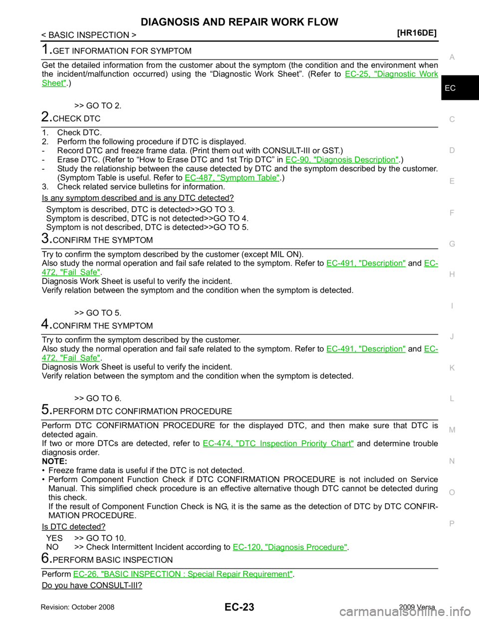
O Diagnostic Work
Sheet " .)
>> GO TO 2. Diagnosis Description " .)
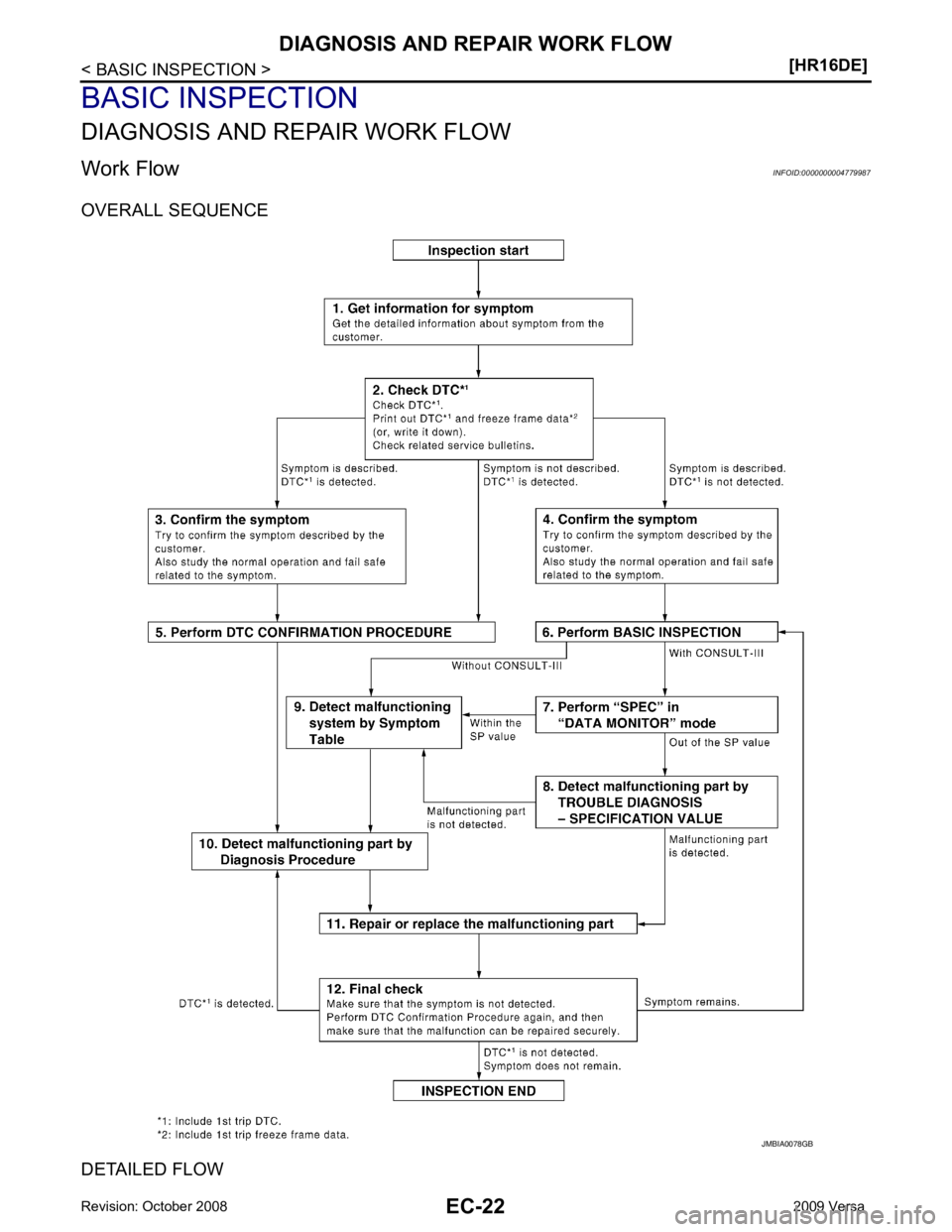
- Study the relationship between the cause detected by DTC and the symptom described by the customer.
(Symptom Table is useful. Refer to EC-487, " Symptom Table " .)
3. Check related service bulletins for information.
Is any symptom described and is any DTC detected? Symptom is described, DTC is detected>>GO TO 3.
Symptom is described, DTC is not detected>>GO TO 4.
Symptom is not described, DTC is detected>>GO TO 5. Description " and
EC- 472, " Fail Safe " .
Diagnosis Work Sheet is useful to verify the incident.
Verify relation between the symptom and t he condition when the symptom is detected.
>> GO TO 5. Description " and
EC- 472, " Fail Safe " .
Diagnosis Work Sheet is useful to verify the incident.
Verify relation between the symptom and t he condition when the symptom is detected.
>> GO TO 6. DTC Inspection Priority Chart " and determine trouble
diagnosis order.
NOTE:
• Freeze frame data is useful if the DTC is not detected.
• Perform Component Function Check if DTC CONF IRMATION PROCEDURE is not included on Service
Manual. This simplified check procedure is an effect ive alternative though DTC cannot be detected during
this check.
If the result of Component Function Check is NG, it is the same as the detection of DTC by DTC CONFIR-
MATION PROCEDURE.
Is DTC detected? YES >> GO TO 10.
NO >> Check Intermittent Incident according to EC-120, " Diagnosis Procedure " .
BASIC INSPECTION : Special Repair Requirement " .
Do you have CONSULT-III?
Page 1380 of 4331

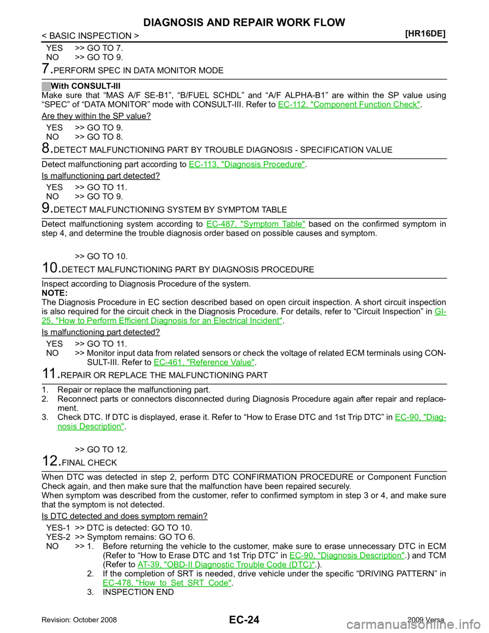
Component Function Check " .
Are they within the SP value? YES >> GO TO 9.
NO >> GO TO 8. Diagnosis Procedure " .
Is malfunctioning part detected? YES >> GO TO 11.
NO >> GO TO 9. Symptom Table " based on the confirmed symptom in
step 4, and determine the trouble diagnosis order based on possible causes and symptom.
>> GO TO 10. 25, " How to Perform Efficient Diagnosis for an Electrical Incident " .
Is malfunctioning part detected? YES >> GO TO 11.
NO >> Monitor input data from related sensors or check the voltage of related ECM terminals using CON-
SULT-III. Refer to EC-461, " Reference Value " .
Diag-
nosis Description " .
>> GO TO 12. YES-1 >> DTC is detected: GO TO 10.
YES-2 >> Symptom remains: GO TO 6.
NO >> 1. Before returning the vehicle to the customer, make sure to erase unnecessary DTC in ECM
(Refer to “How to Erase DTC and 1st Trip DTC” in EC-90, " Diagnosis Description " .) and TCM
(Refer to AT-39, " OBD-II Diagnostic Trouble Code (DTC) " .).
2. If the completion of SRT is needed, drive vehi cle under the specific “DRIVING PATTERN” in
EC-478, " How to Set SRT Code " .
3. INSPECTION END