NISSAN LATIO 2009 Service Repair Manual
Manufacturer: NISSAN, Model Year: 2009, Model line: LATIO, Model: NISSAN LATIO 2009Pages: 4331, PDF Size: 58.04 MB
Page 1351 of 4331
DI
N
O P
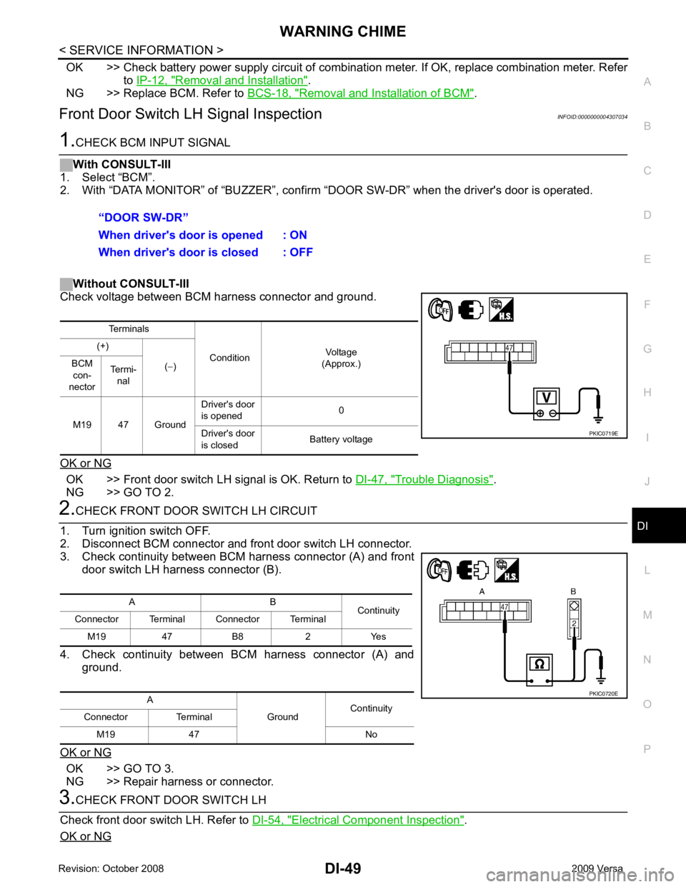
OK >> Check battery power supply circuit of combinati
on meter. If OK, replace combination meter. Refer
to IP-12, " Removal and Installation " .
NG >> Replace BCM. Refer to BCS-18, " Removal and Installation of BCM " .
Front Door Switch LH Signal Inspection INFOID:0000000004307034OK >> Front door switch LH signal is OK. Return to
DI-47, " Trouble Diagnosis " .
NG >> GO TO 2. OK >> GO TO 3.
NG >> Repair harness or connector. Electrical Component Inspection " .
OK or NG
Page 1352 of 4331
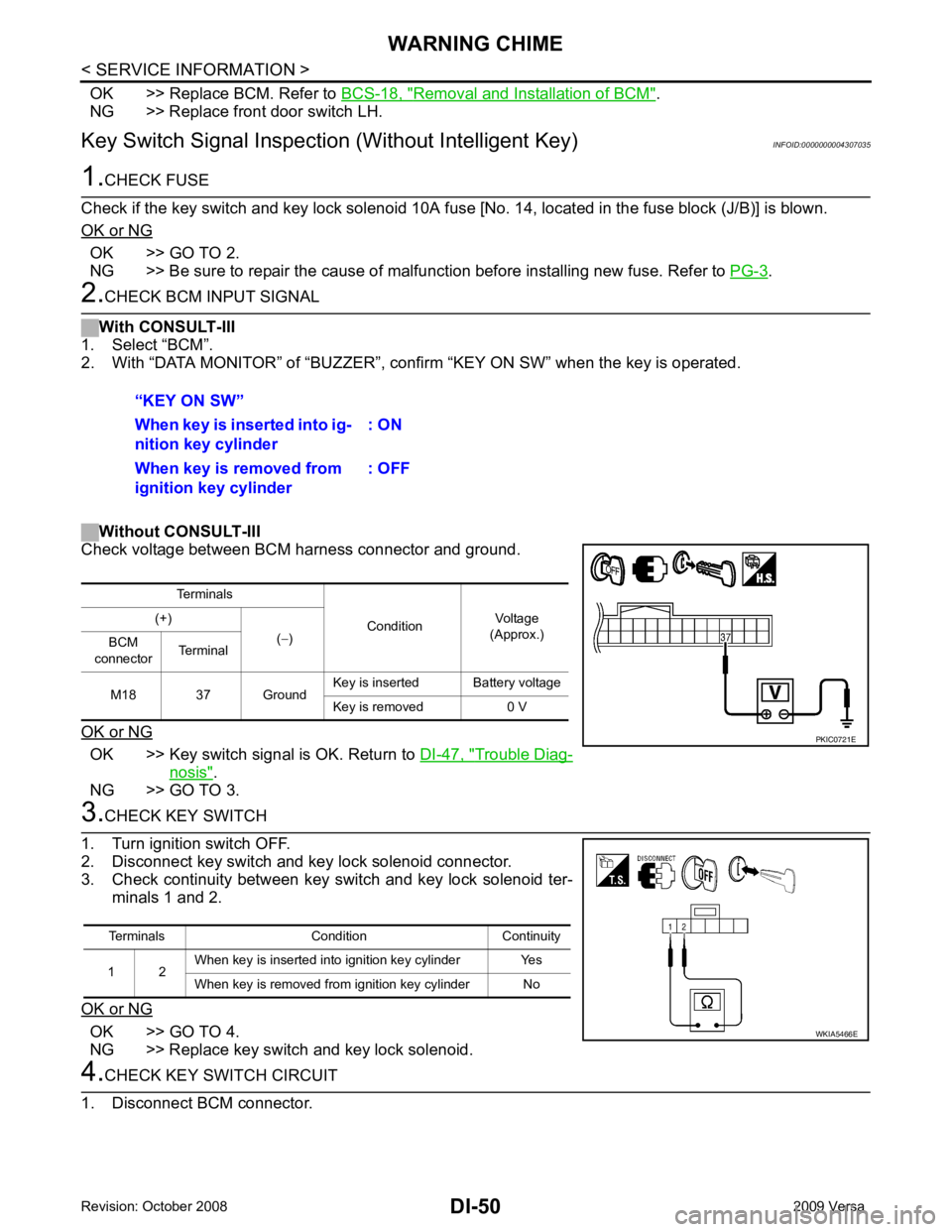
Removal and Installation of BCM " .
NG >> Replace front door switch LH.
Key Switch Signal Inspection (Without Intelligent Key) INFOID:0000000004307035OK >> GO TO 2.
NG >> Be sure to repair the cause of malfunction before installing new fuse. Refer to PG-3 .
OK >> Key switch signal is OK. Return to
DI-47, " Trouble Diag-
nosis " .
NG >> GO TO 3. OK >> GO TO 4.
NG >> Replace key switch and key lock solenoid.
Page 1353 of 4331
DI
N
O P
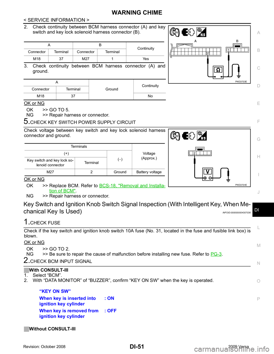
2. Check continuity between BCM harness connector (A) and key
switch and key lock solenoid harness connector (B).
3. Check continuity between BCM harness connector (A) and ground.
OK or NG OK >> GO TO 5.
NG >> Repair harness or connector. OK >> Replace BCM. Refer to
BCS-18, " Removal and Installa-
tion of BCM " .
NG >> Repair harness or connector.
Key Switch and Ignition Knob Switch Signal Inspection (With Intelligent Key, When Me-
chanical Key Is Used) INFOID:0000000004307036OK >> GO TO 2.
NG >> Be sure to repair the cause of malfunction before installing new fuse. Refer to PG-3 .
Page 1354 of 4331
DI-52< SERVICE INFORMATION >
WARNING CHIME
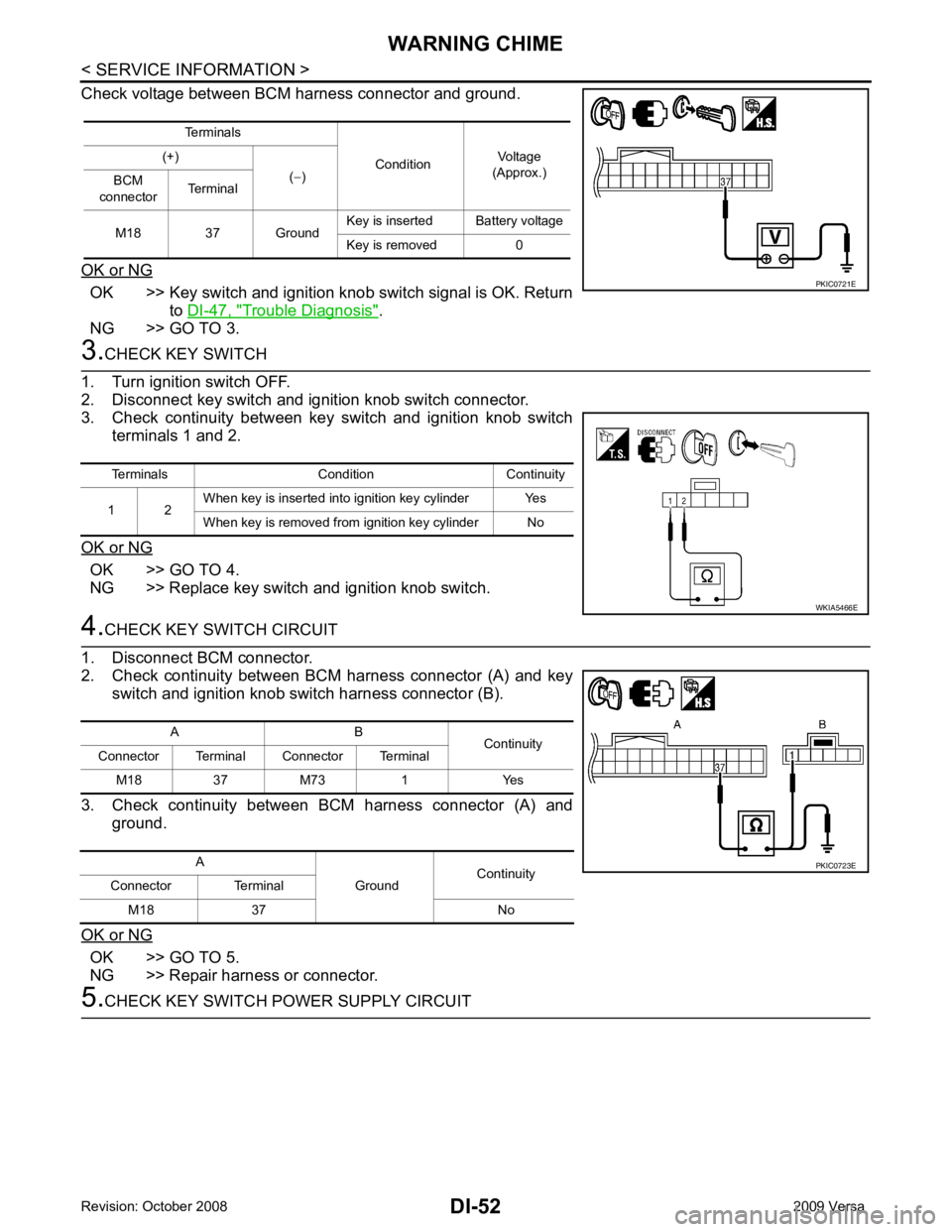
Check voltage between BCM harness connector and ground.
OK or NG OK >> Key switch and ignition knob switch signal is OK. Return
to DI-47, " Trouble Diagnosis " .
NG >> GO TO 3. 3.
CHECK KEY SWITCH
1. Turn ignition switch OFF.
2. Disconnect key switch and ignition knob switch connector.
3. Check continuity between key switch and ignition knob switch
terminals 1 and 2.
OK or NG OK >> GO TO 4.
NG >> Replace key switch and ignition knob switch. 4.
CHECK KEY SWITCH CIRCUIT
1. Disconnect BCM connector.
2. Check continuity between BCM harness connector (A) and key switch and ignition knob switch harness connector (B).
3. Check continuity between BCM harness connector (A) and ground.
OK or NG OK >> GO TO 5.
NG >> Repair harness or connector. 5.
CHECK KEY SWITCH PO WER SUPPLY CIRCUIT
Terminals
ConditionVoltage
(Approx.)
(+)
(− )
BCM
connector Terminal
M18 37 Ground Key is inserted Battery voltage
Key is removed 0 PKIC0721E
Terminals Condition Continuity
1 2 When key is inserted into ignition key cylinder Yes
When key is removed from ignition key cylinder No WKIA5466E
A B
Continuity
Connector Terminal Connector Terminal
M18 37 M73 1 Yes
A GroundContinuity
Connector Terminal
M18 37 No PKIC0723E
Page 1355 of 4331
DI
N
O P
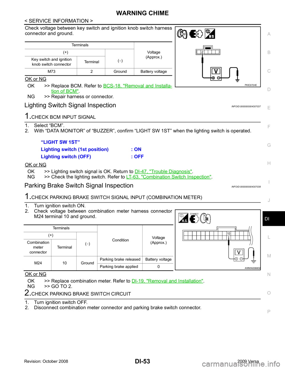
Check voltage between key switch and ignition knob switch harness
connector and ground.
OK or NG OK >> Replace BCM. Refer to
BCS-18, " Removal and Installa-
tion of BCM " .
NG >> Repair harness or connector.
Lighting Switch Signal Inspection INFOID:0000000004307037OK >> Lighting switch signal is OK. Return to
DI-47, " Trouble Diagnosis " .
NG >> Check the lighting switch. Refer to LT-63, " Combination Switch Inspection " .
Parking Brake Switch Signal Inspection INFOID:0000000004307038OK >> Replace combination meter. Refer to
DI-19, " Removal and Installation " .
NG >> GO TO 2. B
Page 1356 of 4331
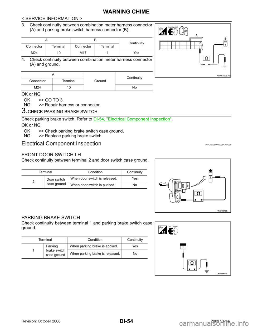
OK >> GO TO 3.
NG >> Repair harness or connector. Electrical Component Inspection " .
OK or NG OK >> Check parking brake switch case ground.
NG >> Replace parking brake switch.
Electrical Component Inspection INFOID:0000000004307039
FRONT DOOR SWITCH LH
Check continuity between terminal 2 and door switch case ground.
PARKING BRAKE SWITCH
Check continuity between terminal 1 and parking brake switch case
ground. A B
Continuity
Connector Terminal Connector Terminal
M24 10 M17 1 Yes
A GroundContinuity
Connector Terminal
M24 10 No B
Page 1357 of 4331
EC
N
O P
CONTENTS
ENGINE CONTROL SYSTEM
HR16DE
BASIC INSPECTION ....... ............................
22
DIAGNOSIS AND REPAIR WORK FLOW .... ....22
Work Flow ........................................................... ....22
Diagnostic Work Sheet ........................................ ....25
INSPECTION AND ADJUSTMENT ................ ....26
BASIC INSPECTION ......... ........................................26
BASIC INSPECTION : Spec ial Repair Require-
ment .................................................................... ....
26
ADDITIONAL SERVICE WHEN REPLACING
CONTROL UNIT .................................................... ....
29
ADDITIONAL SERVICE WHEN REPLACING
CONTROL UNIT : Description ............................ ....
29
ADDITIONAL SERVICE WHEN REPLACING
CONTROL UNIT : Special Repair Requirement .....
29
IDLE SPEED .......................................................... ....30
IDLE SPEED : Description ........................ ..............30
IDLE SPEED : Special R epair Requirement ...........30
IGNITION TIMING .................................................. ....30
IGNITION TIMING : Description .......................... ....30
IGNITION TIMING : Special Repair Requirement ....30
VIN REGISTRATION ............................................. ....30
VIN REGISTRATION : Description ..................... ....30
VIN REGISTRATION : Special Repair Require-
ment .................................................................... ....
31
ACCELERATOR PEDAL RE LEASED POSITION
LEARNING ............................................................ ....
31
ACCELERATOR PEDAL RELEASED POSITION
LEARNING : Description ..................................... ....
31
ACCELERATOR PEDAL RELEASED POSITION
LEARNING : Special Repair Requirement .......... ....
31
THROTTLE VALVE CLO SED POSITION LEARN-
ING ......................................................................... ....
31 THROTTLE VALVE CLOSED POSITION
LEARNING : Description ..................................... ....
31
THROTTLE VALVE CLOSED POSITION
LEARNING : Special Repai r Requirement ..............
31
IDLE AIR VOLUME LEARNING ............................ ....31
IDLE AIR VOLUME LEARNI NG : Description .........31
IDLE AIR VOLUME LEARNI NG : Special Repair
Requirement ........................................................ ....
32
MIXTURE RATIO SELF-LEARNING VALUE
CLEAR ................................................................... ....
33
MIXTURE RATIO SELF-LEARNING VALUE
CLEAR : Description ............................................ ....
33
MIXTURE RATIO SELF-LEARNING VALUE
CLEAR : Special Repair Requirement ................. ....
33
FUNCTION DIAGNOSIS .. ............................35
ENGINE CONTRO L SYSTEM .......................... 35
System Diagram ................................................. ....35
System Description .............................................. ....36
Component Parts Location ................................ ....36
Component Description ....................................... ....40
MULTIPORT FUEL INJECTION SYSTEM ....... 42
System Diagram ................................................. ....42
System Description .............................................. ....42
Component Parts Location ................................ ....45
Component Description ....................................... ....49
ELECTRIC IGNITI ON SYSTEM ........................ 51
System Diagram ................................................. ....51
System Description .............................................. ....51
Component Parts Location ................................ ....52
Component Description ....................................... ....56
AIR CONDITIONING CUT CONTROL .............. 58
System Diagram .................................................. ....58
System Description .............................................. ....58
Component Parts Location ................................ ....59
Component Description ....................................... ....63
Page 1358 of 4331

Page 1359 of 4331
EC
A
N
O P
P0122, P0123 TP SENSOR ...........................
..171
Description .......................................................... ..171
DTC Logic ........................................................... ..171
Wiring Diagram ................................................... ..172
Diagnosis Procedure ........................................... ..172
Component Inspection ........................................ ..174
Special Repair Requirem ent .................................174
P0125 ECT SENSOR ..................................... ..175
Description .......................................................... ..175
DTC Logic ........................................................... ..175
Diagnosis Procedure ........................................... ..176
Component Inspection ........................................ ..176
P0127 IAT SENSOR ....................................... ..178
Description .......................................................... ..178
DTC Logic ........................................................... ..178
Diagnosis Procedure ........................................... ..179
Component Inspection ........................................ ..179
P0128 THERMOSTAT FUNCTION ................ ..180
DTC Logic ........................................................... ..180
Diagnosis Procedure ........................................... ..180
Component Inspection ........................................ ..181
P0130 A/F SENSOR 1 .................................... ..182
Description .......................................................... ..182
DTC Logic ........................................................... ..182
Component Function Check ................................ ..183
Wiring Diagram ................................................... ..185
Diagnosis Procedure ........................................... ..185
P0131 A/F SENSOR 1 .................................... ..188
Description .......................................................... ..188
DTC Logic ........................................................... ..188
Wiring Diagram ................................................... ..190
Diagnosis Procedure ........................................... ..190
P0132 A/F SENSOR 1 .................................... ..193
Description .......................................................... ..193
DTC Logic ........................................................... ..193
Wiring Diagram ................................................... ..195
Diagnosis Procedure ........................................... ..195
P0133 A/F SENSOR 1 .................................... ..198
Description .......................................................... ..198
DTC Logic ........................................................... ..198
Wiring Diagram ................................................... ..200
Diagnosis Procedure ........................................... ..201
P0137 HO2S2 ................................................. ..204
Description .......................................................... ..204
DTC Logic ........................................................... ..204
Component Function Check ................................ ..205
Wiring Diagram ................................................... ..207
Diagnosis Procedure ........................................... ..207
Component Inspection ........................................ ..209
P0138 HO2S2 ................................................. ..212
Description .......................................................... ..212
DTC Logic ........................................................... ..212 Component Function Check ................................
..213
Wiring Diagram .................................................... ..215
Diagnosis Procedure ........................................... ..215
Component Inspection ......................................... ..218
P0139 HO2S2 .................................................. 221
Description ........................................................... ..221
DTC Logic ............................................................ ..221
Component Function Check ................................ ..222
Wiring Diagram .................................................... ..224
Diagnosis Procedure ........................................... ..224
Component Inspection ......................................... ..226
P0171 FUEL INJECTION SYSTEM FUNC-
TION ................................................................ 229
DTC Logic ............................................................ ..229
Wiring Diagram .................................................... ..231
Diagnosis Procedure ........................................... ..231
P0172 FUEL INJECTION SYSTEM FUNC-
TION ................................................................ 235
DTC Logic ............................................................ ..235
Wiring Diagram .................................................... ..237
Diagnosis Procedure ........................................... ..237
P0181 FTT SENSOR ....................................... 240
Description ........................................................... ..240
DTC Logic ............................................................ ..240
Wiring Diagram .................................................... ..242
Diagnosis Procedure ........................................... ..242
Component Inspection ......................................... ..244
P0182, P0183 FTT SENSOR .......................... 245
Description ........................................................... ..245
DTC Logic ............................................................ ..245
Wiring Diagram .................................................... ..246
Diagnosis Procedure ........................................... ..246
Component Inspection ......................................... ..248
P0222, P0223 TP SENSOR ............................ 249
Description ........................................................... ..249
DTC Logic ............................................................ ..249
Wiring Diagram .................................................... ..250
Diagnosis Procedure ........................................... ..250
Component Inspection ......................................... ..252
Special Repair Requiremen t ..................................252
P0300, P0301, P0302, P0303, P0304 MIS-
FIRE ................................................................. 253
DTC Logic ............................................................ ..253
Diagnosis Procedure ........................................... ..254
P0327, P0328 KS ............................................ 259
Description ........................................................... ..259
DTC Logic ............................................................ ..259
Wiring Diagram .................................................... ..260
Diagnosis Procedure ........................................... ..260
Component Inspection ......................................... ..261
P0335 CKP SENSOR (POS) ........................... 263
Description ........................................................... ..263
Page 1360 of 4331
