transmission NISSAN LATIO 2009 Service Repair Manual
[x] Cancel search | Manufacturer: NISSAN, Model Year: 2009, Model line: LATIO, Model: NISSAN LATIO 2009Pages: 4331, PDF Size: 58.04 MB
Page 1249 of 4331
CVT
N
O P
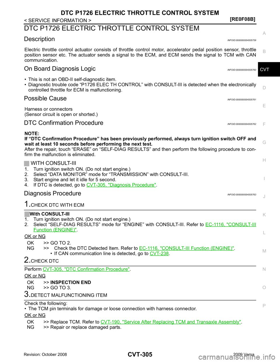
DTC P1726 ELECTRIC TH
ROTTLE CONTROL SYSTEM
Description INFOID:0000000004305759
Electric throttle control actuator consists of throttle control motor, accelerator pedal position sensor, throttle
position sensor etc. The actuator sends a signal to the ECM, and ECM sends the signal to TCM with CAN
communication.
On Board Diagnosis Logic INFOID:0000000004305760
• This is not an OBD-II self-diagnostic item.
• Diagnostic trouble code “P1726 ELEC TH CONTROL” wit h CONSULT-III is detected when the electronically
controlled throttle for ECM is malfunctioning.
Possible Cause INFOID:0000000004305761
Harness or connectors
(Sensor circuit is open or shorted.)
DTC Confirmation Procedure INFOID:0000000004305762
NOTE:
If “DTC Confirmation Procedure” has been previously performed, alw ays turn ignition switch OFF and
wait at least 10 seconds before performing the next test.
After the repair, touch “ERASE” on “SELF-DIAG RESU LTS” and then perform the following procedure to con-
firm the malfunction is eliminated.
WITH CONSULT-III
1. Turn ignition switch ON. (Do not start engine.)
2. Select “DATA MONITOR” mode for “TRANSMISSION” with CONSULT-III.
3. Start engine and let it idle for 5 second.
4. If DTC is detected, go to CVT-305, " Diagnosis Procedure " .
Diagnosis Procedure INFOID:0000000004305763 CONSULT-III
Function (ENGINE) " .
OK or NG OK >> GO TO 2.
NG >> Check the DTC Detected Item. Refer to EC-1116, " CONSULT-III Function (ENGINE) " .
• If CAN communication line is detected, go to CVT-238 .
DTC Confirmation Procedure " .
OK or NG OK >>
INSPECTION END
NG >> GO TO 3. OK >> Replace TCM. Refer to
CVT-190, " Service After Replacing TCM and Transaxle Assembly " .
NG >> Repair or replace damaged parts.
Page 1252 of 4331
![NISSAN LATIO 2009 Service Repair Manual CVT-308< SERVICE INFORMATION >
[RE0F08B]
DTC P1740 LOCK-UP SELECT
SOLENOID VALVE CIRCUIT
Diagnosis Procedure INFOID:00000000043057701.
CHECK INPUT SIGNAL
With CONSULT-III
1. Turn ignition switch ON.](/img/5/57359/w960_57359-1251.png "NISSAN LATIO 2009 Service Repair Manual CVT-308< SERVICE INFORMATION >
[RE0F08B]
DTC P1740 LOCK-UP SELECT
SOLENOID VALVE CIRCUIT
Diagnosis Procedure INFOID:00000000043057701.
CHECK INPUT SIGNAL
With CONSULT-III
1. Turn ignition switch ON.")
CVT-308< SERVICE INFORMATION >
[RE0F08B]
DTC P1740 LOCK-UP SELECT
SOLENOID VALVE CIRCUIT
Diagnosis Procedure INFOID:00000000043057701.
CHECK INPUT SIGNAL
With CONSULT-III
1. Turn ignition switch ON.
2. Select “SELECTION FROM MENU” in “DATA MONI TOR” mode for “TRANSMISSION” with CONSULT-III.
3. Read out the value of “LUSEL SOL OUT”.
Without CONSULT-III
1. Turn ignition switch ON.
2. Check voltage between TCM connector terminal and ground.
3. Turn ignition switch OFF.
4. Disconnect the TCM connector.
5. Check if there is continuity between connector terminal and ground.
OK or NG OK >> GO TO 5.
NG >> GO TO 2. 2.
CHECK LOCK-UP SELECT SOLENOID VALVE CIRCUIT
1. Turn ignition switch OFF.
2. Disconnect TCM connector.
3. Check resistance between TCM connector terminal and ground.
OK or NG OK >> GO TO 5.
NG >> GO TO 3. 3.
CHECK VALVE RESISTANCE
1. Turn ignition switch OFF.
2. Disconnect CVT unit harness connector. Item name Condition Display value
LUSEL SOL OUT Selector lever in “P” and “N”
positions ON
Wait at least for 5 seconds
with the selector lever in
“R”, “D” and “L” positions OFF
Name Connector Terminal Condition Voltage
(Approx.)
Lock-up
select sole-
noid valve E31 4 - Ground Selector lever in “P” and
“N” positions Battery
voltage
Wait at least for 5 sec-
onds with the selector le-
ver in “R”, “D” and “L”
positions 0 V SCIA7955E
Solenoid valve Connector Terminal
Resistance (Ap-
prox.)
Lock-up select solenoid
valve E31 4 - Ground 6 - 19
Ω SCIA4692E
Page 1254 of 4331
Diagnosis Procedure " .
Diagnosis Procedure INFOID:0000000004305776OBD-II Diagnostic Trouble Code (DTC) " .
4. Turn ignition switch OFF, and wait for 10 seconds or more.
5. Start engine.
6. Confirm self-diagnostic results again. Refer to CVT-230, " CONSULT-III Function (TRANSMISSION) " .
Is the “ P1745 L/PRESS CONTROL ” displayed?
YES >> Replace TCM. Refer to
CVT-190, " Service After Replacing TCM and Transaxle Assembly " .
NO >> INSPECTION END
Page 1255 of 4331
CVT
N
O P
DTC P1777 STEP MOTOR - CIRCUIT
Description INFOID:0000000004305777
• The step motor is included in the control valve assembly.
• The step motor changes the step with turning 4 coils ON/OF F according to the signal from TCM. As a result,
the flow of line pressure to primary pu lley is changed and pulley ratio is controlled
CONSULT-III Reference Val ue in Data Monitor Mode INFOID:0000000004305778
Remarks: Specification data are reference values.
On Board Diagnosis Logic INFOID:0000000004305779
• This is an OBD-II self-diagnostic item.
• Diagnostic trouble code “P1777 STEP MOTR CIRC” with CONSULT-III is detected under the following con-
ditions.
- When operating step motor ON and OFF, there is no proper change in the voltage of TCM terminal which corresponds to it.
Possible Cause INFOID:0000000004305780
• Step motor
• Harness or connectors
(Step motor circuit is open or shorted.)
DTC Confirmation Procedure INFOID:0000000004305781
CAUTION:
Always drive vehicle at a safe speed.
NOTE:
If “DTC Confirmation Procedure” has been previously performed, alw ays turn ignition switch OFF and
wait at least 10 seconds before performing the next test.
After the repair, touch “ERASE” on “SELF-DIAG RESU LTS” and then perform the following procedure to con-
firm the malfunction is eliminated.
WITH CONSULT-III
1. Turn ignition switch ON and select “DATA MO NITOR” mode for “TRANSMISSION” with CONSULT-III.
2. Drive vehicle for at least 5 consecutive seconds.
3. If DTC is detected, go to CVT-313, " Diagnosis Procedure " .
WITH GST
Follow the procedure “WITH CONSULT-III”. Item name Condition Display value (Approx.)
STM STEP
During driving−
20 step - 180 step
SMCOIL A
Changes ON⇔OFF.
SMCOIL B
SMCOIL C
SMCOIL D
Page 1257 of 4331
![NISSAN LATIO 2009 Service Repair Manual DTC P1777 STEP MOTOR - CIRCUIT
CVT-313
< SERVICE INFORMATION >
[RE0F08B] D
E
F
G H
I
J
K L
M A
B CVT
N
O P
Diagnosis Procedure
INFOID:00000000043057831.
CHECK INPUT SIGNALS
With CONSULT-III
1. Start e](/img/5/57359/w960_57359-1256.png "NISSAN LATIO 2009 Service Repair Manual DTC P1777 STEP MOTOR - CIRCUIT
CVT-313
< SERVICE INFORMATION >
[RE0F08B] D
E
F
G H
I
J
K L
M A
B CVT
N
O P
Diagnosis Procedure
INFOID:00000000043057831.
CHECK INPUT SIGNALS
With CONSULT-III
1. Start e")
DTC P1777 STEP MOTOR - CIRCUIT
CVT-313
< SERVICE INFORMATION >
[RE0F08B] D
E
F
G H
I
J
K L
M A
B CVT
N
O P
Diagnosis Procedure
INFOID:00000000043057831.
CHECK INPUT SIGNALS
With CONSULT-III
1. Start engine.
2. Select “SELECTION FROM MENU” in “DATA MONI TOR” mode for “TRANSMISSION” with CONSULT-III.
3. Start vehicle and read out the value of “STM STEP”, “SMCOIL A”, “SMCOIL B”, “SMCOIL C”, and
“SMCOIL D”.
OK or NG OK >> GO TO 4.
NG >> GO TO 2. 2.
CHECK HARNESS BETWEEN TCM AND STEP MOTOR
1. Turn ignition switch OFF.
2. Disconnect CVT unit connector and TCM connector.
3. Check continuity between TCM connector terminals and CVT
unit harness connector terminals.
4. If OK, check harness for short to ground and short to power.
5. If OK, check continuity between body ground and CVT assembly.
6. Reinstall any part removed.
OK or NG OK >> GO TO 3.
NG >> Repair open circuit or short to ground or short to power in harness or connectors. 3.
CHECK STEP MOTOR
Check step motor. Refer to CVT-314, " Component Inspection " .
OK or NG OK >> GO TO 4.
NG >> Repair or replace damaged parts. 4.
CHECK DTC
Perform CVT-311, " DTC Confirmation Procedure " .
OK or NG OK >>
INSPECTION END
NG >> GO TO 5.
Item name Condition Display value (Approx.)
STM STEP
During driving−
20 step - 180 step
SMCOIL A
Changes ON⇔OFF.
SMCOIL B
SMCOIL C
SMCOIL D Item Connector Terminal Continuity
TCM E31 11 Yes
CVT unit harness connector F46 6
TCM E31 12 Yes
CVT unit harness connector F46 7
TCM E31 20 Yes
CVT unit harness connector F46 8
TCM E31 21 Yes
CVT unit harness connector F46 9 SCIA4695E
Page 1259 of 4331
CVT
N
O P
DTC P1778 STEP MOTOR - FUNCTION
Description INFOID:0000000004305785
• The step motor is included in the control valve assembly.
• The step motor's 4 aspects of ON/OFF change according to the signal from TCM. As a result, the flow of line
pressure to primary pulley is changed and pulley ratio is controlled.
• This diagnosis item is detected when electrical system is OK, but mechanical system is NG.
• This diagnosis item is detected when the state of the changing the speed mechanism in unit does not oper-
ate normally.
CONSULT-III Reference Val ue in Data Monitor Mode INFOID:0000000004305786
Remarks: Specification data are reference values.
On Board Diagnosis Logic INFOID:0000000004305787
• This is an OBD-II self-diagnostic item.
• Diagnostic trouble code “P1778 STEP MOTR/FNC” with CO NSULT-III is detected under the following condi-
tions.
- When not changing the pulley ratio according to the instruction of TCM.
Possible Cause INFOID:0000000004305788
Step motor
DTC Confirmation Procedure INFOID:0000000004305789
CAUTION:
• Always drive vehicle at a safe speed.
• Before starting “DTC Confirmation Procedure”, confirm “Hi” or “Mid” or “Low” fixation by “PRI SPEED” and “VEHICLE SPEED” on “DATA MONITOR MODE”.
• If hi-geared fixation occurred, go to CVT-316, " Diagnosis Procedure " .
NOTE:
If “DTC Confirmation Procedure” has been previously performed, alw ays turn ignition switch OFF and
wait at least 10 seconds before performing the next test.
After the repair, touch “ERASE” on “SELF-DIAG RESU LTS” and then perform the following procedure to con-
firm the malfunction is eliminated.
WITH CONSULT-III
1. Turn ignition switch ON and select “DATA MO NITOR” mode for “TRANSMISSION” with CONSULT-III.
2. Make sure that output voltage of CVT fluid temperature sensor is within the range below.
ATF TEMP SEN: 1.0 - 2.0 V
If out of range, drive the vehicle to decrease the voltage (warm up the fluid) or stop engine to
increase the voltage (c ool down the fluid)
3. Select “DATA MONITOR” mode for “TRANSMISSION” with CONSULT-III.
4. Start engine and maintain the following conditions for at least 30 consecutive seconds.
TEST START FROM 0 km/h (0 MPH)
CONSTANT ACCELERATION: Keep 30 sec or more
VEHICLE SPEED: 10 km/h (6 MPH) or more
ACC PEDAL OPEN: More than 1.0/8
RANGE: “D” position
ENG SPEED: 450 rpm or more
5. If DTC is detected, go to CVT-316, " Diagnosis Procedure " .
WITH GST
Follow the procedure “WITH CONSULT-III”. Item name Condition Display value (Approx.)
STM STEP During driving−
20 step - 180 step
GEAR RATIO 2.56 - 0.43
Page 1260 of 4331
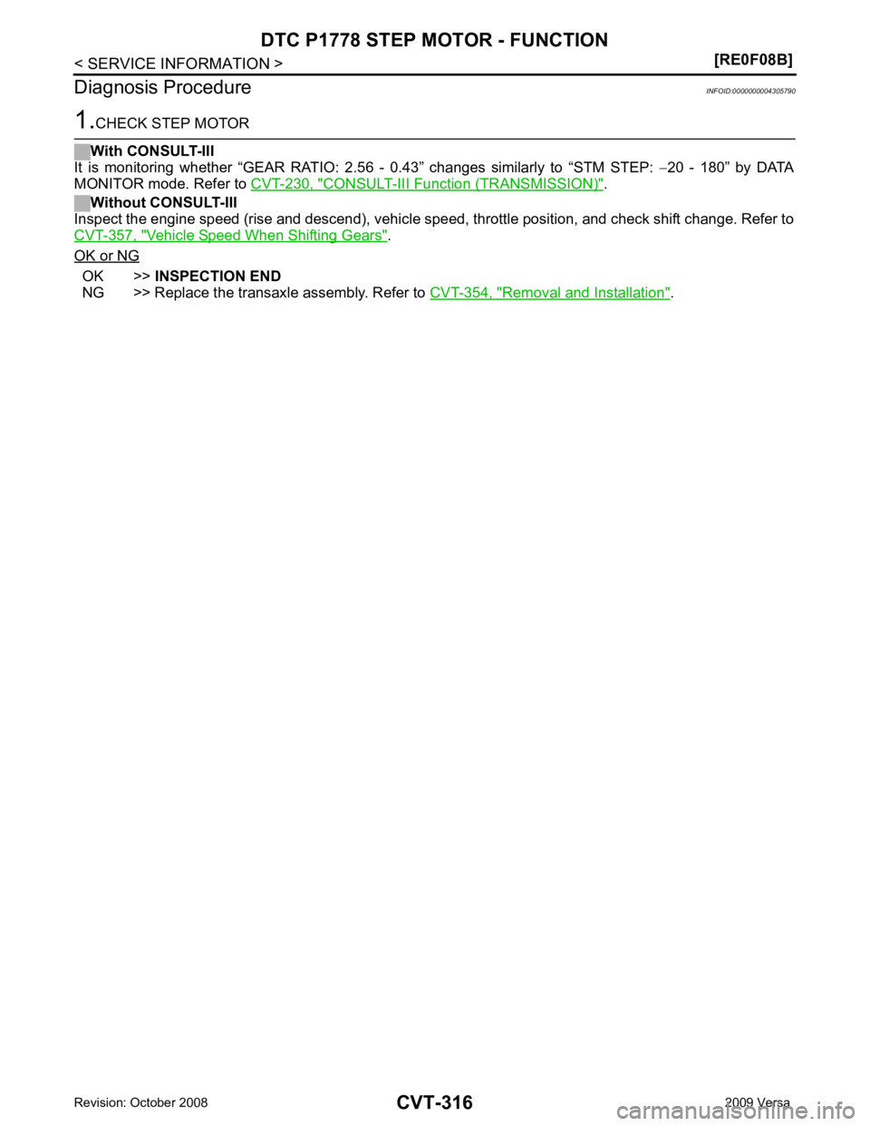
CONSULT-III Function (TRANSMISSION) " .
Without CONSULT-III
Inspect the engine speed (rise and descend), vehicle speed, throttle position, and check shift change. Refer to
CVT-357, " Vehicle Speed When Shifting Gears " .
OK or NG OK >>
INSPECTION END
NG >> Replace the transaxle assembly. Refer to CVT-354, " Removal and Installation " .
Page 1263 of 4331
![NISSAN LATIO 2009 Service Repair Manual OVERDRIVE CONTROL SWITCH
CVT-319
< SERVICE INFORMATION >
[RE0F08B] D
E
F
G H
I
J
K L
M A
B CVT
N
O P
Perform the self-diagnosis check. Refer to
CVT-230, " CONSULT-III Functi
on (TRANSMISSION) " .
Is](/img/5/57359/w960_57359-1262.png "NISSAN LATIO 2009 Service Repair Manual OVERDRIVE CONTROL SWITCH
CVT-319
< SERVICE INFORMATION >
[RE0F08B] D
E
F
G H
I
J
K L
M A
B CVT
N
O P
Perform the self-diagnosis check. Refer to
CVT-230, \" CONSULT-III Functi
on (TRANSMISSION) \" .
Is")
OVERDRIVE CONTROL SWITCH
CVT-319
< SERVICE INFORMATION >
[RE0F08B] D
E
F
G H
I
J
K L
M A
B CVT
N
O P
Perform the self-diagnosis check. Refer to
CVT-230, " CONSULT-III Functi
on (TRANSMISSION) " .
Is any malfunction of the “ U1000 CAN COMM CIRCUIT ” indicated in the results?
YES >> Check CAN communication line. Refer to
CVT-238 .
NO >> GO TO 2. 2.
CHECK OVERDRIVE CO NTROL SWITCH SIGNAL
With CONSULT-III
1. Turn ignition switch ON.
2. Select “ECU INPUT SIGNALS” in “DATA MONITO R” mode for “TRANSMISSION” with CONSULT-III.
3. Read out ON/OFF switching action of the “SPORT MODE SW”.
OK or NG OK >>
INSPECTION END
NG >> GO TO 3. 3.
CHECK OVERDRIVE CONTROL SWITCH
Check overdrive control switch. Refer to CVT-320, " Component Inspection "
OK or NG
OK >> GO TO 4.
NG >> Repair or replace damaged parts. 4.
CHECK SELF-DIAGNOSTIC RESU LTS (COMBINATION METER)
Perform self-diagnosis check. Refer to DI-10, " Self-Diagnosis Mode of Combination Meter " .
Is any malfunction detected by self-diagnostic? YES >> Check the malfunctioning system.
NO - 1 >> With intelligent key: GO TO 5.
NO - 2 >> Without intelligent key: GO TO 6. 5.
CHECK OVERDRIVE CO NTROL SWITCH CIRCUIT
1. Turn ignition switch OFF.
2. Disconnect CVT device connector and combination meter connector.
3. Check continuity between CVT device harness connector (A)
terminal and combination meter harness connector (B) terminal.
Item name Condition Display value
SPORT MODE SW While pushing overdrive
cancel switch ON
Other conditions OFF Item Connector Terminal Continuity
CVT device harness connector M38 1 Yes
Combination meter harness
connector M24 8 SCIA7949E
Page 1266 of 4331
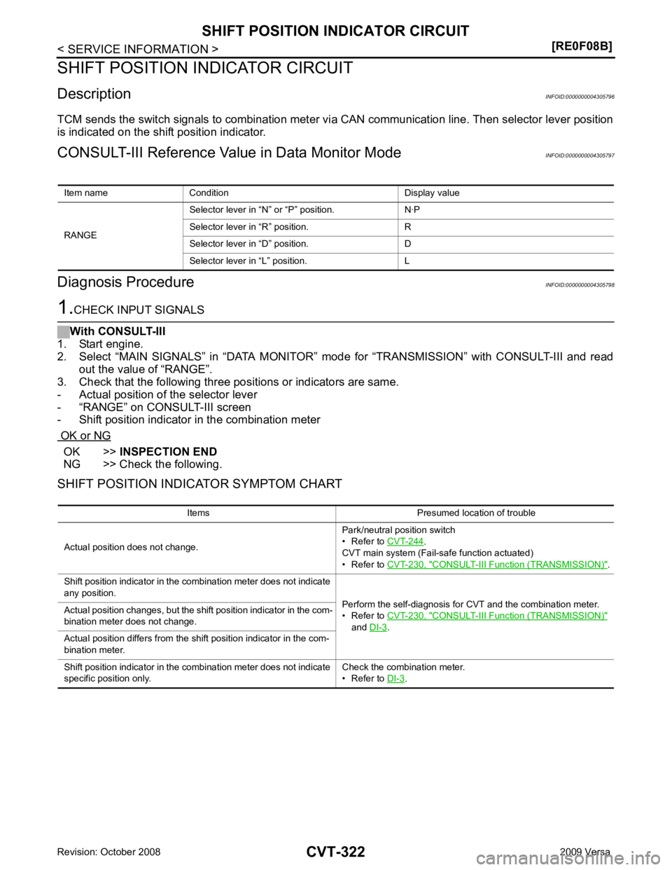
OK >>
INSPECTION END
NG >> Check the following.
SHIFT POSITION INDICATOR SYMPTOM CHART Item name Condition Display value
RANGE Selector lever in “N
” or “P” position. N·P
Selector lever in “R” position. R
Selector lever in “D” position. D
Selector lever in “L” position. L Items Presumed location of trouble
Actual position does not change. Park/neutral position switch
• Refer to CVT-244 .
CVT main system (Fail-safe function actuated)
• Refer to CVT-230, " CONSULT-III Functi
on (TRANSMISSION) " .
Shift position indicator in the combination meter does not indicate
any position. Perform the self-diagnosis for CVT and the combination meter.
• Refer to CVT-230, " CONSULT-III Functi
on (TRANSMISSION) "
and DI-3 .
Actual position changes, but the shift position indicator in the com-
bination meter does not change.
Actual position differs from the shift position indicator in the com-
bination meter.
Shift position indicator in the combination meter does not indicate
specific position only. Check the combination meter.
• Refer to DI-3 .
Page 1270 of 4331
![NISSAN LATIO 2009 Service Repair Manual CVT-326< SERVICE INFORMATION >
[RE0F08B]
TROUBLE DIAGNOSIS FOR SYMPTOMS
O/D OFF indicator lamp does not come on for about 2 seconds when turning ignition switch ON.
DIAGNOSTIC PROCEDURE 1.
CHECK CAN](/img/5/57359/w960_57359-1269.png "NISSAN LATIO 2009 Service Repair Manual CVT-326< SERVICE INFORMATION >
[RE0F08B]
TROUBLE DIAGNOSIS FOR SYMPTOMS
O/D OFF indicator lamp does not come on for about 2 seconds when turning ignition switch ON.
DIAGNOSTIC PROCEDURE 1.
CHECK CAN")
CVT-326< SERVICE INFORMATION >
[RE0F08B]
TROUBLE DIAGNOSIS FOR SYMPTOMS
O/D OFF indicator lamp does not come on for about 2 seconds when turning ignition switch ON.
DIAGNOSTIC PROCEDURE 1.
CHECK CAN COMMUNICATION LINE
Perform the self-diagnosis check. Refer to CVT-230, " CONSULT-III Function (TRANSMISSION) " .
Is any malfunction of the “ U1000 CAN COMM CIRCUIT ” indicated in the results?
YES >> Check CAN communication line. Refer to
CVT-238 .
NO >> GO TO 2. 2.
CHECK TCM POWER SOURCE
1. Turn ignition switch ON.
2. Check voltage between TCM connector terminals and ground.
Refer to CVT-296, " Wiring Diagram - CVT - POWER " .
OK or NG OK >> GO TO 4.
NG >> GO TO 3. 3.
DETECT MALFUNCTIONING ITEM
Check the following.
• Harness for short or open between ignition switch and TCM connector terminal 10, 19
Refer to CVT-296, " Wiring Diagram - CVT - POWER " .
• 10 A fuse (No.49, located in the IPDM E/R). Refer to CVT-296, " Wiring Diagram - CVT - POWER " .
• Ignition switch. Refer to PG-3 .
OK or NG OK >> GO TO 4.
NG >> Repair or replace damaged parts. 4.
CHECK TCM GROUND CIRCUIT
1. Turn ignition switch OFF.
2. Disconnect TCM connector.
3. Check continuity between TCM connector terminals and ground. Refer to CVT-296, " Wiring Diagram - CVT - POWER " .
OK or NG OK >> GO TO 5.
NG >> Repair open circuit or short to ground or short to power
in harness or connectors. 5.
DETECT MALFUNCTIONING ITEM
Check the following.
• Harness and fuse for short or open between ignition switch and O/D OFF indicator lamp Refer to PG-3 .
OK or NG OK >> GO TO 6.
NG >> Repair or replace damaged parts. 6.
CHECK SYMPTOMName
Connec-
tor Terminal Voltage (Approx.)
Power supply E31 10 Battery voltage
19 Battery voltage SCIA4737E
Name
Connec-
tor Terminal Continuity
Ground E32 25
Yes
48 SCIA2671E