NISSAN LATIO 2009 Service Repair Manual
Manufacturer: NISSAN, Model Year: 2009, Model line: LATIO, Model: NISSAN LATIO 2009Pages: 4331, PDF Size: 58.04 MB
Page 2401 of 4331
![NISSAN LATIO 2009 Service Repair Manual ON BOARD REFUELING VAPOR RECOVERY (ORVR)
EC-1045
< SERVICE INFOMATION >
[MR TYPE 2] C
D E
F
G H
I
J
K L
M A EC
NP
O
NG >> Repair or replace one-way fuel valve with fuel tank. 11.
CHECK ONE-WAY FUEL VA NISSAN LATIO 2009 Service Repair Manual ON BOARD REFUELING VAPOR RECOVERY (ORVR)
EC-1045
< SERVICE INFOMATION >
[MR TYPE 2] C
D E
F
G H
I
J
K L
M A EC
NP
O
NG >> Repair or replace one-way fuel valve with fuel tank. 11.
CHECK ONE-WAY FUEL VA](/img/5/57359/w960_57359-2400.png)
ON BOARD REFUELING VAPOR RECOVERY (ORVR)
EC-1045
< SERVICE INFOMATION >
[MR TYPE 2] C
D E
F
G H
I
J
K L
M A EC
NP
O
NG >> Repair or replace one-way fuel valve with fuel tank. 11.
CHECK ONE-WAY FUEL VALVE-II
1. Make sure that fuel is drained from the tank.
2. Remove fuel filler tube and hose.
3. Check one-way fuel valve for operation as follows. When a stick is inserted, the valve should open, when removing
stick it should close.
Do not drop any material into the tank.
OK or NG OK >>
INSPECTION END
NG >> Replace fuel filler tube or replace one-way fuel valve with fuel tank.
Component Inspection INFOID:0000000004499920
REFUELING EVAP VAPOR CUT VALVE With CONSULT-III
1. Remove fuel tank. Refer to FL-9 .
2. Drain fuel from the tank as follows:
a. Remove fuel feed hose located on the fuel gauge retainer.
b. Connect a spare fuel hose, one side to fuel gauge retainer where the hose was removed and the other side to a fuel container.
c. Drain fuel using “FUEL PUMP RELAY” in “ACTIVE TEST” mode with CONSULT-III.
3. Check refueling EVAP vapor cut valve for being stuck to close as follows. Blow air into the refueling EVAP vapor cut valv e (from the end of EVAP/ORVR line hose), and check that
the air flows freely into the tank.
4. Check refueling EVAP vapor cut valve for being stuck to open as follows.
a. Connect vacuum pump to hose end.
b. Remove fuel gauge retainer with fuel gauge unit. Always replace O-ring with new one.
c. Put fuel tank upside down.
d. Apply vacuum pressure to hose end [ −13.3 kPa ( −100 mmHg, −3.94 inHg)] with fuel gauge retainer
remaining open and check that the pressure is applicable. SEF665U
Page 2402 of 4331
![NISSAN LATIO 2009 Service Repair Manual EC-1046< SERVICE INFOMATION >
[MR TYPE 2]
ON BOARD REFUELING VAPOR RECOVERY (ORVR)
Without CONSULT-III
1. Remove fuel tank. Refer to FL-9 .
2. Drain fuel from the tank as follows:
a. Remove fuel gau NISSAN LATIO 2009 Service Repair Manual EC-1046< SERVICE INFOMATION >
[MR TYPE 2]
ON BOARD REFUELING VAPOR RECOVERY (ORVR)
Without CONSULT-III
1. Remove fuel tank. Refer to FL-9 .
2. Drain fuel from the tank as follows:
a. Remove fuel gau](/img/5/57359/w960_57359-2401.png)
EC-1046< SERVICE INFOMATION >
[MR TYPE 2]
ON BOARD REFUELING VAPOR RECOVERY (ORVR)
Without CONSULT-III
1. Remove fuel tank. Refer to FL-9 .
2. Drain fuel from the tank as follows:
a. Remove fuel gauge retainer.
b. Drain fuel from the tank using a handy pump into a fuel container.
3. Check refueling EVAP vapor cut valve for being stuck to close as follows. Blow air into the refueling EVAP vapor cut valv e (from the end of EVAP/ORVR line hose), and check that
the air flows freely into the tank.
4. Check refueling EVAP vapor cut valve for being stuck to open as follows.
a. Connect vacuum pump to hose end.
b. Remove fuel gauge retainer with fuel gauge unit. Always replace O-ring with new one.
c. Put fuel tank upside down.
d. Apply vacuum pressure to hose end [ −13.3 kPa ( −100 mmHg, −3.94 inHg)] with fuel gauge retainer
remaining open and check that the pressure is applicable.
1. Filler tube 2. Recirculation line 3. EVAP/ORVR line
4. Vacuum/pressure handy pump 5. Fuel tank BBIA0694E
Page 2403 of 4331
![NISSAN LATIO 2009 Service Repair Manual ON BOARD REFUELING VAPOR RECOVERY (ORVR)
EC-1047
< SERVICE INFOMATION >
[MR TYPE 2] C
D E
F
G H
I
J
K L
M A EC
NP
O
DRAIN FILTER
1. Check visually for insect nests in the drain filter air inlet.
2. Ch NISSAN LATIO 2009 Service Repair Manual ON BOARD REFUELING VAPOR RECOVERY (ORVR)
EC-1047
< SERVICE INFOMATION >
[MR TYPE 2] C
D E
F
G H
I
J
K L
M A EC
NP
O
DRAIN FILTER
1. Check visually for insect nests in the drain filter air inlet.
2. Ch](/img/5/57359/w960_57359-2402.png)
ON BOARD REFUELING VAPOR RECOVERY (ORVR)
EC-1047
< SERVICE INFOMATION >
[MR TYPE 2] C
D E
F
G H
I
J
K L
M A EC
NP
O
DRAIN FILTER
1. Check visually for insect nests in the drain filter air inlet.
2. Check visually for cracks or flaws in the appearance.
3. Check visually for cracks or flaws in the hose.
4. Blow air into port A and check that it flows freely out of port B.
5. Block port B.
6. Blow air into port A and check that there is no leakage.
7. If NG, replace drain filter. 1. Filler tube 2. Recirculation line 3. EVAP/ORVR line
4. Vacuum/pressure handy pump 5. Fuel tank BBIA0694E
PBIB3641E
Page 2404 of 4331
![NISSAN LATIO 2009 Service Repair Manual EC-1048< SERVICE INFOMATION >
[MR TYPE 2]
POSITIVE CRANKCASE VENTILATION
POSITIVE CRANKCASE VENTILATION
Description INFOID:0000000004499921
SYSTEM DESCRIPTION
This system returns blow-by gas to the in NISSAN LATIO 2009 Service Repair Manual EC-1048< SERVICE INFOMATION >
[MR TYPE 2]
POSITIVE CRANKCASE VENTILATION
POSITIVE CRANKCASE VENTILATION
Description INFOID:0000000004499921
SYSTEM DESCRIPTION
This system returns blow-by gas to the in](/img/5/57359/w960_57359-2403.png)
EC-1048< SERVICE INFOMATION >
[MR TYPE 2]
POSITIVE CRANKCASE VENTILATION
POSITIVE CRANKCASE VENTILATION
Description INFOID:0000000004499921
SYSTEM DESCRIPTION
This system returns blow-by gas to the intake manifold.
The positive crankcase ventilation (PCV) valve is prov ided to conduct crankcase blow-by gas to the intake
manifold. During partial throttle operation of the engine, the intake manifold sucks the blow-by gas through the
PCV valve. Normally, the capacity of the valve is suff icient to handle any blow-by and a small amount of venti-
lating air. The ventilating air is then drawn from the air inlet tubes into the crankcase. In this process the air
passes through the hose connecting air inlet tubes to rocker cover.
Under full-throttle condition, the manifold vacuum is in sufficient to draw the blow-by flow through the valve.
The flow goes through the hose connection in the reverse direction.
On vehicles with an excessively high blow-by, the valve does not
meet the requirement. This is because some of the flow will go
through the hose connection to the air inlet tubes under all condi-
tions.
Component Inspection INFOID:0000000004499922
PCV (POSITIVE CRANKCASE VENTILATION) VALVE
With engine running at idle, remove PCV valve from rocker cover. A
properly working valve makes a hissing noise as air passes through
it. A strong vacuum should be felt immediately when a finger is
placed over valve inlet. JMBIA0686GB
PBIB1588E
PBIB1589E
Page 2405 of 4331
![NISSAN LATIO 2009 Service Repair Manual POSITIVE CRANKCASE VENTILATION
EC-1049
< SERVICE INFOMATION >
[MR TYPE 2] C
D E
F
G H
I
J
K L
M A EC
NP
O
PCV VALVE VENTILATION HOSE
1. Check hoses and hose connections for leaks.
2. Disconnect all ho NISSAN LATIO 2009 Service Repair Manual POSITIVE CRANKCASE VENTILATION
EC-1049
< SERVICE INFOMATION >
[MR TYPE 2] C
D E
F
G H
I
J
K L
M A EC
NP
O
PCV VALVE VENTILATION HOSE
1. Check hoses and hose connections for leaks.
2. Disconnect all ho](/img/5/57359/w960_57359-2404.png)
POSITIVE CRANKCASE VENTILATION
EC-1049
< SERVICE INFOMATION >
[MR TYPE 2] C
D E
F
G H
I
J
K L
M A EC
NP
O
PCV VALVE VENTILATION HOSE
1. Check hoses and hose connections for leaks.
2. Disconnect all hoses and clean with compressed air. If any hose cannot be freed of obstructions, replace. S-ET277
Page 2406 of 4331

U0101-U1001 " .
• Check that no DTC is displayed in “SELF DIAGNOSIS RESULT” mode of “BCM” before erasing the
detected DTC in “ENGINE” mode with CONSULT-III.
• When replacing ECM, refer to EC-1083, " Procedure After Replacing ECM " .
Page 2407 of 4331

EC
NP
O
ON BOARD DIAGNOSTIC (OBD) SYSTEM
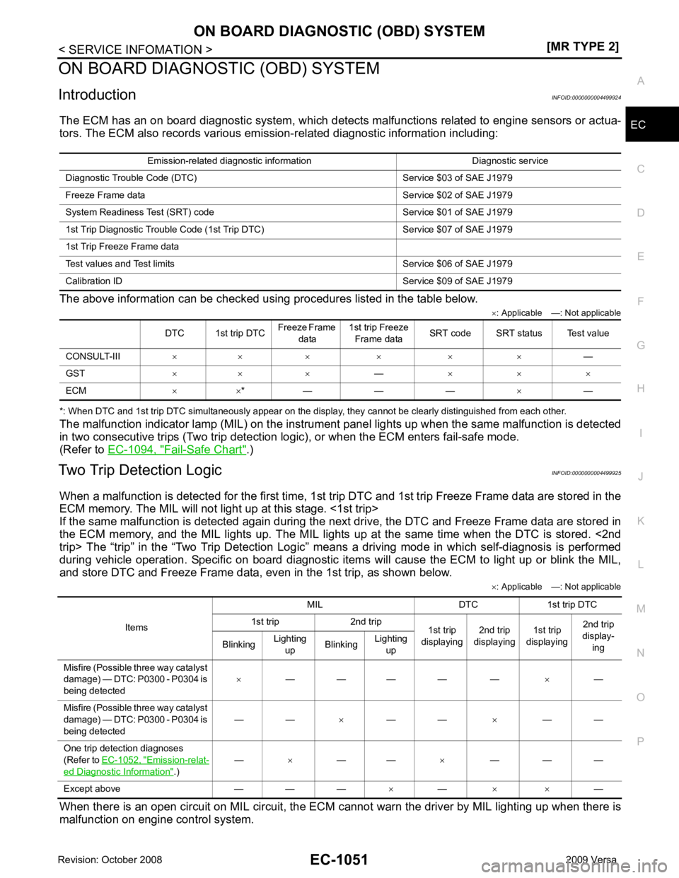
Introduction INFOID:0000000004499924
The ECM has an on board diagnostic system, which detects malfunctions related to engine sensors or actua-
tors. The ECM also records various emis sion-related diagnostic information including:
The above information can be checked using procedures listed in the table below. ×: Applicable —: Not applicable
*: When DTC and 1st trip DTC simultaneously appear on the display, they cannot be clearly distinguished from each other.
The malfunction indicator lamp (MIL) on the instrument panel lights up when the same malfunction is detected
in two consecutive trips (Two trip detection logic), or when the ECM enters fail-safe mode.
(Refer to EC-1094, " Fail-Safe Chart " .)
Two Trip Detection Logic INFOID:0000000004499925
When a malfunction is detected for the first time, 1st tr ip DTC and 1st trip Freeze Frame data are stored in the
ECM memory. The MIL will not light up at this stage. <1st trip>
If the same malfunction is detected again during the next drive, the DTC and Freeze Frame data are stored in
the ECM memory, and the MIL lights up. The MIL lights up at the same time when the DTC is stored. <2nd
trip> The “trip” in the “Two Trip Detection Logic” m eans a driving mode in which self-diagnosis is performed
during vehicle operation. Specific on board diagnostic item s will cause the ECM to light up or blink the MIL,
and store DTC and Freeze Frame data, even in the 1st trip, as shown below.
×: Applicable —: Not applicable
When there is an open circuit on MIL circuit, the ECM c annot warn the driver by MIL lighting up when there is
malfunction on engine control system. Emission-related diagnostic information Diagnostic service
Diagnostic Tr ouble Code (DTC) Service $03 of SAE J1979
Freeze Frame data Service $02 of SAE J1979
System Readiness Test (SRT) code Service $01 of SAE J1979
1st Trip Diagnostic Trou ble Code (1st Trip DTC) Service $07 of SAE J1979
1st Trip Freeze Frame data
Test values and Test limi ts Service $06 of SAE J1979
Calibration ID Servic e $09 of SAE J1979
DTC 1st trip DTC Freeze Frame
data 1st trip Freeze
Frame data SRT code SRT status Test value
CONSULT-III × × × × × × —
GST × × × —× × ×
ECM × ×* — — — ×— Items
MIL DTC 1st trip DTC
1st trip 2nd trip 1st trip
displaying 2nd trip
displaying 1st trip
displaying 2nd trip
display-
ing
Blinking Lighting
up Blinking
Lighting
up
Misfire (Possible three way catalyst
damage) — DTC: P0300 - P0304 is
being detected ×
— — — — — ×—
Misfire (Possible three way catalyst
damage) — DTC: P0300 - P0304 is
being detected — —
×— — ×— —
One trip detection diagnoses
(Refer to EC-1052, " Emission-relat-
ed Diagnostic Information " .)
—
×— — ×— — —
Except above — — — ×— × × —
Page 2408 of 4331

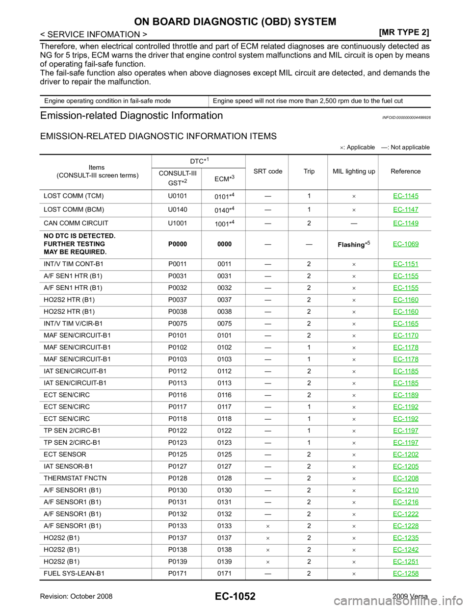
Items
(CONSULT-III screen terms) DTC*
1
SRT code Trip MIL lighting up Reference
CONSULT-III
GST* 2
ECM*3
LOST COMM (TCM) U0101 0101*4
— 1 ×EC-1145 LOST COMM (BCM) U0140
0140*4
— 1 ×EC-1147 CAN COMM CIRCUIT U1001
1001*4
— 2 — EC-1149INT/V TIM CONT-B1 P0011 0011 — 2
×EC-1151 A/F SEN1 HTR (B1) P0031 0031 — 2
×EC-1155 A/F SEN1 HTR (B1) P0032 0032 — 2
×EC-1155 HO2S2 HTR (B1) P0037 0037 — 2
×EC-1160 HO2S2 HTR (B1) P0038 0038 — 2
×EC-1160 INT/V TIM V/CIR-B1 P0075 0075 — 2
×EC-1165 MAF SEN/CIRCUIT-B1 P0101 0101 — 2
×EC-1170 MAF SEN/CIRCUIT-B1 P0102 0102 — 1
×EC-1178 MAF SEN/CIRCUIT-B1 P0103 0103 — 1
×EC-1178 IAT SEN/CIRCUIT-B1 P0112 0112 — 2
×EC-1185 IAT SEN/CIRCUIT-B1 P0113 0113 — 2
×EC-1185 ECT SEN/CIRC P0116 0116 — 2
×EC-1189 ECT SEN/CIRC P0117 0117 — 1
×EC-1192 ECT SEN/CIRC P0118 0118 — 1
×EC-1192 TP SEN 2/CIRC-B1 P0122 0122 — 1
×EC-1197 TP SEN 2/CIRC-B1 P0123 0123 — 1
×EC-1197 ECT SENSOR P0125 0125 — 2
×EC-1202 IAT SENSOR-B1 P0127 0127 — 2
×EC-1205 THERMSTAT FNCTN P0128 0128 — 2
×EC-1208 A/F SENSOR1 (B1) P0130 0130 — 2
×EC-1210 A/F SENSOR1 (B1) P0131 0131 — 2
×EC-1216 A/F SENSOR1 (B1) P0132 0132 — 2
×EC-1222 A/F SENSOR1 (B1) P0133 0133
×2 ×EC-1228 HO2S2 (B1) P0137 0137
×2 ×EC-1235 HO2S2 (B1) P0138 0138
×2 ×EC-1242 HO2S2 (B1) P0139 0139
×2 ×EC-1251 FUEL SYS-LEAN-B1 P0171 0171 — 2
×EC-1258
Page 2409 of 4331

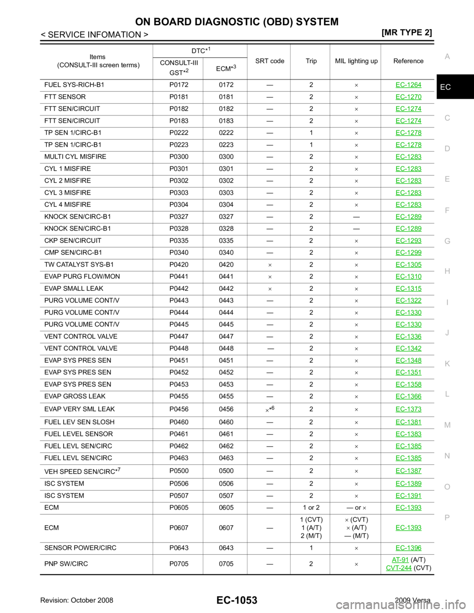
EC
NP
O
FUEL SYS-RICH-B1 P0172 0172 — 2
×EC-1264 FTT SENSOR P0181 0181 — 2
×EC-1270 FTT SEN/CIRCUIT P0182 0182 — 2
×EC-1274 FTT SEN/CIRCUIT P0183 0183 — 2
×EC-1274 TP SEN 1/CIRC-B1 P0222 0222 — 1
×EC-1278 TP SEN 1/CIRC-B1 P0223 0223 — 1
×EC-1278 MULTI CYL MISFIRE P0300 0300 — 2
×EC-1283 CYL 1 MISFIRE P0301 0301 — 2
×EC-1283 CYL 2 MISFIRE P0302 0302 — 2
×EC-1283 CYL 3 MISFIRE P0303 0303 — 2
×EC-1283 CYL 4 MISFIRE P0304 0304 — 2
×EC-1283 KNOCK SEN/CIRC-B1 P0327 0327 — 2 —
EC-1289KNOCK SEN/CIRC-B1 P0328 0328 — 2 —
EC-1289CKP SEN/CIRCUIT P0335 0335 — 2
×EC-1293 CMP SEN/CIRC-B1 P0340 0340 — 2
×EC-1299 TW CATALYST SYS-B1 P0420 0420
× 2 ×EC-1305 EVAP PURG FLOW/MON P0441 0441
×2 ×EC-1310 EVAP SMALL LEAK P0442 0442
×2 ×EC-1315 PURG VOLUME CONT/V P0443 0443 — 2
×EC-1322 PURG VOLUME CONT/V P0444 0444 — 2
×EC-1330 PURG VOLUME CONT/V P0445 0445 — 2
×EC-1330 VENT CONTROL VALVE P0447 0447 — 2
×EC-1336 VENT CONTROL VALVE P0448 0448 — 2
×EC-1342 EVAP SYS PRES SEN P0451 0451 — 2
×EC-1348 EVAP SYS PRES SEN P0452 0452 — 2
×EC-1351 EVAP SYS PRES SEN P0453 0453 — 2
×EC-1358 EVAP GROSS LEAK P0455 0455 — 2
×EC-1366 EVAP VERY SML LEAK P0456 0456
×*6
2 ×EC-1373 FUEL LEV SEN SLOSH P0460 0460 — 2
×EC-1381 FUEL LEVEL SEN
SOR P0461 0461 — 2 ×EC-1383 FUEL LEVL SEN/C
IRC P0462 0462 — 2 ×EC-1385 FUEL LEVL SEN/C
IRC P0463 0463 — 2 ×EC-1385 VEH SPEED SEN/CIRC*
7
P0500 0500 — 2 ×EC-1387 ISC SYSTEM P0506 0506 — 2
×EC-1389 ISC SYSTEM P0507 0507 — 2
×EC-1391 ECM P0605 0605 — 1 or 2 — or
×EC-1393 ECM P0607 0607 —
1 (CVT)
1 (A/T)
2 (M/T) ×
(CVT)
× (A/T)
— (M/T) EC-1393SENSOR POWER/CIRC P0643 0643 — 1
×EC-1396 PNP SW/CIRC P0705 0705 — 2
×AT-91 (A/T)
CVT-244 (CVT)
Items
(CONSULT-III screen terms) DTC*
1
SRT code Trip MIL lighting up Reference
CONSULT-III
GST* 2
ECM*3
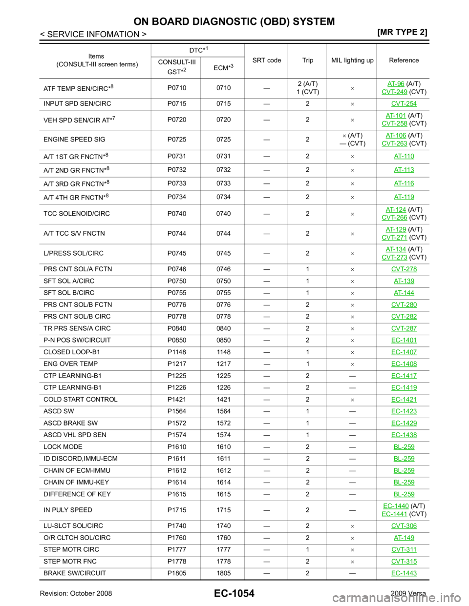
Page 2410 of 4331

(A/T)
CVT-249 (CVT)
INPUT SPD SEN/CIRC P0715 0715 — 2 ×CVT-254 VEH SPD SEN/CIR AT*
7
P0720 0720 — 2 ×AT-101 (A/T)
CVT-258 (CVT)
ENGINE SPEED SIG P0725 0725 — 2 ×
(A/T)
— (CVT) AT-106 (A/T)
CVT-263 (CVT)
A/T 1ST GR FNCTN* 8
P0731 0731 — 2 ×AT-110 A/T 2ND GR FNCTN*
8
P0732 0732 — 2 ×AT-113 A/T 3RD GR FNCTN*
8
P0733 0733 — 2 ×AT-116 A/T 4TH GR FNCTN*
8
P0734 0734 — 2 ×AT-119 TCC SOLENOID/CIRC P0740 0740 — 2
×AT-124 (A/T)
CVT-266 (CVT)
A/T TCC S/V FNCTN P0744 0744 — 2 ×AT-129 (A/T)
CVT-271 (CVT)
L/PRESS SOL/CIRC P0745 0745 — 2 ×AT-134 (A/T)
CVT-273 (CVT)
PRS CNT SOL/A FCTN P0746 0746 — 1 ×CVT-278 SFT SOL A/CIRC P0750 0750 — 1
×AT-139 SFT SOL B/CIRC P0755 0755 — 1
×AT-144 PRS CNT SOL/B FCTN P0776 0776 — 2
×CVT-280 PRS CNT SOL/B CIRC P0778 0778 — 2
×CVT-282 TR PRS SENS/A CIRC P0840 0840 — 2
×CVT-287 P-N POS SW/CIRCUIT P0850 0850 — 2
×EC-1401 CLOSED LOOP-B1 P1148 1148 — 1
×EC-1407 ENG OVER TEMP P1217 1217 — 1
×EC-1408 CTP LEARNING-B1 P1225 1225 — 2 —
EC-1417CTP LEARNING-B1 P1226 1226 — 2 —
EC-1419COLD START CONTROL P1421 1421 — 2
×EC-1421 ASCD SW P1564 1564 — 1 —
EC-1423ASCD BRAKE SW P1572 1572 — 1 —
EC-1429ASCD VHL SPD SEN P1574 1574 — 1 —
EC-1438LOCK MODE P1610 1610 — 2 —
BL-259ID DISCORD,IMMU-ECM P1611 1611 — 2 —
BL-259CHAIN OF ECM-IMMU P1612 1612 — 2 —
BL-259CHAIN OF IMMU-KEY P1614 1614 — 2 —
BL-259DIFFERENCE OF KEY P1615 1615 — 2 —
BL-259IN PULY SPEED P1715 1715 — 2 —
EC-1440 (A/T)
EC-1441 (CVT)
LU-SLCT SOL/CIRC P1740 1740 — 2 ×CVT-306 O/R CLTCH SOL/CIRC P1760 1760 — 2
×AT-149 STEP MOTR CIRC P1777 1777 — 1
×CVT-311 STEP MOTR FNC P1778 1778 — 2
×CVT-315 BRAKE SW/CIRCUIT P1805 1805 — 2 —
EC-1443Items
(CONSULT-III screen terms) DTC*
1
SRT code Trip MIL lighting up Reference
CONSULT-III
GST* 2
ECM*3