NISSAN LATIO 2009 Service Repair Manual
Manufacturer: NISSAN, Model Year: 2009, Model line: LATIO, Model: NISSAN LATIO 2009Pages: 4331, PDF Size: 58.04 MB
Page 351 of 4331
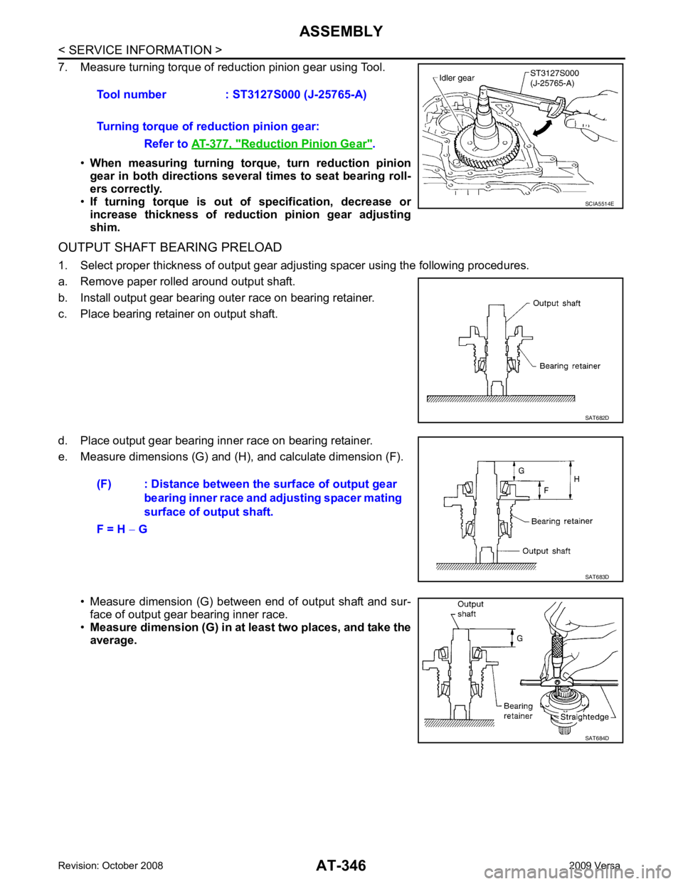
Reduction Pinion Gear " .
SAT682D
SAT684D
Page 352 of 4331
ASSEMBLY
AT-347
< SERVICE INFORMATION >
D
E
F
G H
I
J
K L
M A
B AT
N
O P
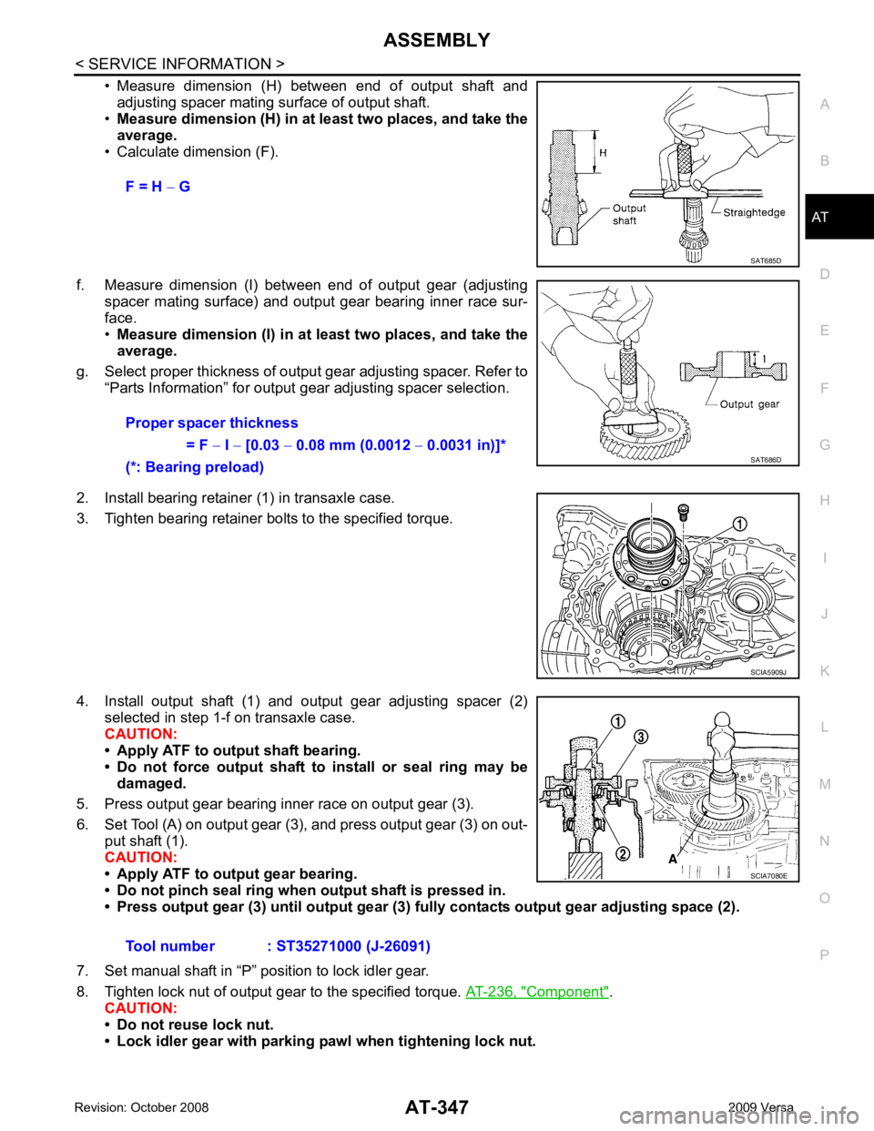
• Measure dimension (H) between end of output shaft and
adjusting spacer mating surface of output shaft.
• Measure dimension (H) in at least two places, and take the
average.
• Calculate dimension (F).
f. Measure dimension (I) betw een end of output gear (adjusting
spacer mating surface) and output gear bearing inner race sur-
face.
• Measure dimension (I) in at least two places, and take the
average.
g. Select proper thickness of output gear adjusting spacer. Refer to “Parts Information” for output gear adjusting spacer selection.
2. Install bearing retainer (1) in transaxle case.
3. Tighten bearing retainer bolts to the specified torque.
4. Install output shaft (1) and output gear adjusting spacer (2) selected in step 1-f on transaxle case.
CAUTION:
• Apply ATF to output shaft bearing.
• Do not force output shaft to install or seal ring may be
damaged.
5. Press output gear bearing inner race on output gear (3).
6. Set Tool (A) on output gear (3), and press output gear (3) on out- put shaft (1).
CAUTION:
• Apply ATF to output gear bearing.
• Do not pinch seal ring when output shaft is pressed in.
• Press output gear (3) until output gear (3 ) fully contacts output gear adjusting space (2).
7. Set manual shaft in “P” position to lock idler gear.
8. Tighten lock nut of output gear to the specified torque. AT-236, " Component " .
CAUTION:
• Do not reuse lock nut.
• Lock idler gear with parking pawl when tightening lock nut. F = H
− G SAT685D
Proper spacer thickness
= F − I − [0.03 − 0.08 mm (0.0012 − 0.0031 in)]*
(*: Bearing preload) SAT686D
SCIA5909J
Tool number : ST35271000 (J-26091) SCIA7080E
Page 353 of 4331
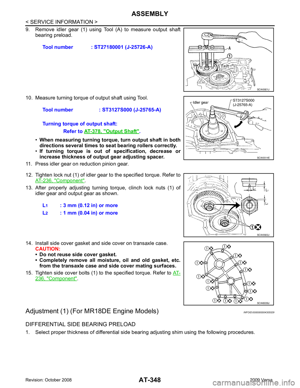
Component " .
13. After properly adjusting turning torque, clinch lock nuts (1) of idler gear and output gear as shown.
14. Install side cover gasket and side cover on transaxle case. CAUTION:
• Do not reuse side cover gasket.
• Completely remove all moisture, oil and old gasket, etc. from the transaxle case and side cover mating surfaces.
15. Tighten side cover bolts (1) to the specified torque. Refer to AT-236, " Component " .
Adjustment (1) (For MR18DE Engine Models) INFOID:0000000004305529
DIFFERENTIAL SIDE BEARING PRELOAD
1. Select proper thickness of differential side bearing adjusting shim using the following procedures. Tool number : ST27180001 (J-25726-A)
Output Shaft " .
SCIA6039J
Page 354 of 4331
ASSEMBLY
AT-349
< SERVICE INFORMATION >
D
E
F
G H
I
J
K L
M A
B AT
N
O P
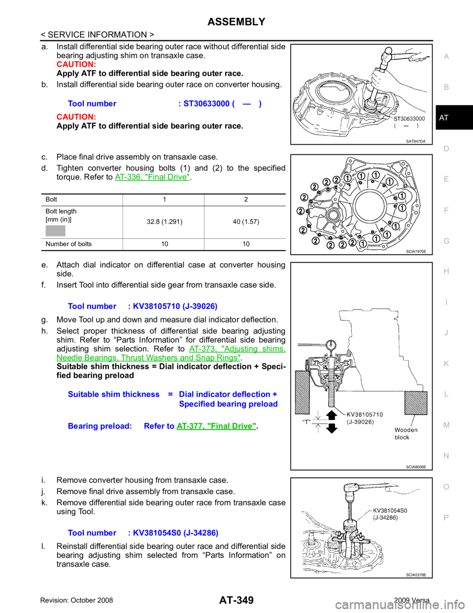
a. Install differential side bearing outer race without differential side
bearing adjusting shim on transaxle case.
CAUTION:
Apply ATF to differential side bearing outer race.
b. Install differential side bearing outer race on converter housing.
CAUTION:
Apply ATF to differential side bearing outer race.
c. Place final drive assembly on transaxle case.
d. Tighten converter housing bolts (1) and (2) to the specified torque. Refer to AT-336, " Final Drive " .
e. Attach dial indicator on differential case at converter housing side.
f. Insert Tool into differential side gear from transaxle case side.
g. Move Tool up and down and measure dial indicator deflection.
h. Select proper thickness of differential side bearing adjusting shim. Refer to “Parts Information” for differential side bearing
adjusting shim selection. Refer to AT-373, " Adjusting shims,
Needle Bearings, Thrust Washers and Snap Rings " .
Suitable shim thickness = Dial indicator deflection + Speci-
fied bearing preload
i. Remove converter housing from transaxle case.
j. Remove final drive assembly from transaxle case.
k. Remove differential side bearing outer race from transaxle case using Tool.
l. Reinstall differential side bearing outer race and differential side bearing adjusting shim selected from “Parts Information” on
transaxle case. Tool number : ST30633000 ( — ) SAT947DA
Bolt 1 2
Bolt length
[mm (in)] 32.8 (1.291) 40 (1.57)
Number of bolts 10 10 SCIA7970E
Tool number : KV38105710 (J-39026)
Suitable shim thickness = D ial indicator deflection +
Specified bearing preload
Bearing preload: Refer to AT-377, " Final Drive " .
SCIA8006E
Tool number : KV381054S0 (J-34286)
SCIA5378E
Page 355 of 4331
AT-350< SERVICE INFORMATION >
ASSEMBLY
m. Reinstall converter housing on transaxle case and ti ghten converter housing bolts to the specified torque.
Refer to AT-236, " Component " .
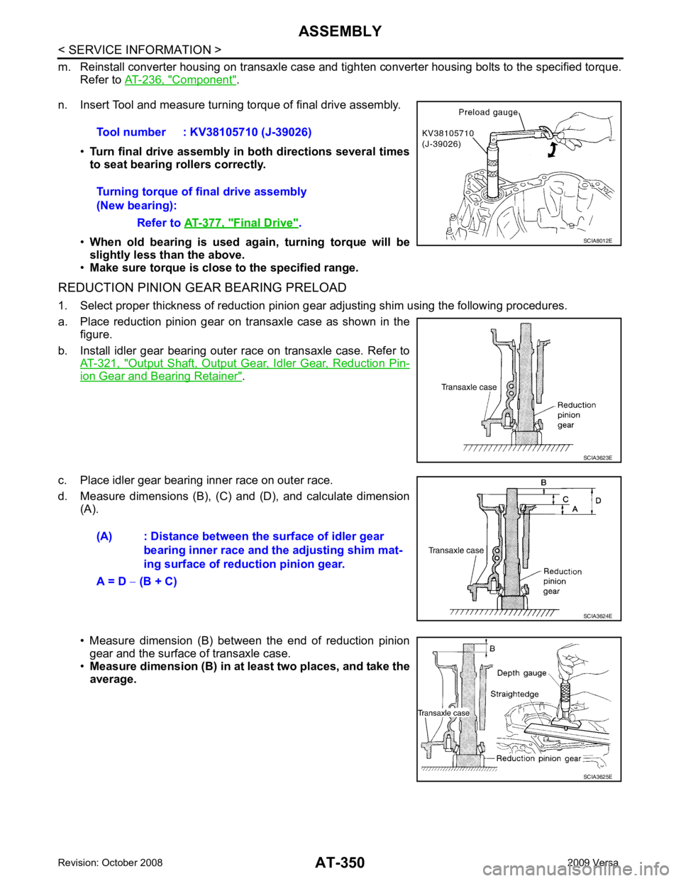
n. Insert Tool and measure turning torque of final drive assembly.
•Turn final drive assembly in both directions several times
to seat bearing rollers correctly.
• When old bearing is used again, turning torque will be
slightly less than the above.
• Make sure torque is close to the specified range.
REDUCTION PINION GEAR BEARING PRELOAD
1. Select proper thickness of reduction pinion gear adjusting shim using the following procedures.
a. Place reduction pinion gear on transaxle case as shown in the figure.
b. Install idler gear bearing outer race on transaxle case. Refer to AT-321, " Output Shaft, Output Gear, Idler Gear, Reduction Pin-
ion Gear and Bearing Retainer " .
c. Place idler gear bearing inner race on outer race.
d. Measure dimensions (B), (C) and (D), and calculate dimension (A).
• Measure dimension (B) between the end of reduction pinion gear and the surface of transaxle case.
• Measure dimension (B) in at least two places, and take the
average. Tool number : KV38105710 (J-39026)
Turning torque of final drive assembly
(New bearing):
Refer to AT-377, " Final Drive " .
SCIA8012E
SCIA3623E
(A) : Distance between the surface of idler gear
bearing inner race and the adjusting shim mat-
ing surface of redu ction pinion gear.
A = D − (B + C) SCIA3624E
SCIA3625E
Page 356 of 4331
ASSEMBLY
AT-351
< SERVICE INFORMATION >
D
E
F
G H
I
J
K L
M A
B AT
N
O P
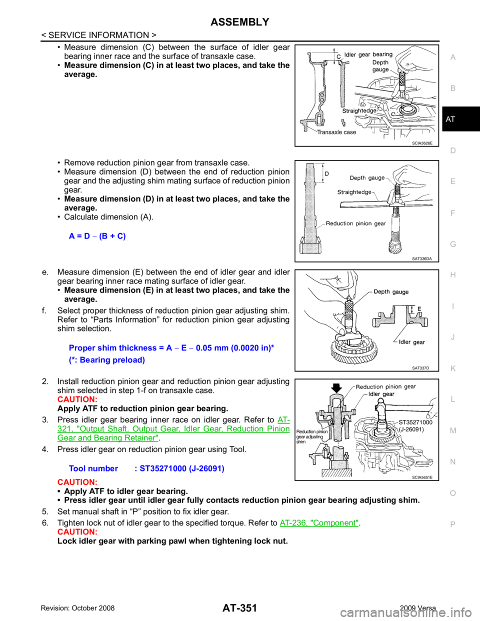
• Measure dimension (C) between the surface of idler gear
bearing inner race and the surface of transaxle case.
• Measure dimension (C) in at least two places, and take the
average.
• Remove reduction pinion gear from transaxle case.
• Measure dimension (D) between the end of reduction pinion gear and the adjusting shim mating surface of reduction pinion
gear.
• Measure dimension (D) in at least two places, and take the
average.
• Calculate dimension (A).
e. Measure dimension (E) between the end of idler gear and idler gear bearing inner race mating surface of idler gear.
• Measure dimension (E) in at least two places, and take the
average.
f. Select proper thickness of reduction pinion gear adjusting shim. Refer to “Parts Information” for reduction pinion gear adjusting
shim selection.
2. Install reduction pinion gear and reduction pinion gear adjusting shim selected in step 1-f on transaxle case.
CAUTION:
Apply ATF to reduction pinion gear bearing.
3. Press idler gear bearing inner race on idler gear. Refer to AT-321, " Output Shaft, Output Gear, Idler Gear, Reduction Pinion
Gear and Bearing Retainer " .
4. Press idler gear on reduction pinion gear using Tool.
CAUTION:
• Apply ATF to idler gear bearing.
• Press idler gear until idler gear fully contacts reduction pinion gear bearing adjusting shim.
5. Set manual shaft in “P” position to fix idler gear.
6. Tighten lock nut of idler gear to the specified torque. Refer to AT-236, " Component " .
CAUTION:
Lock idler gear with parking pa wl when tightening lock nut. SCIA3626E
A = D
− (B + C) SAT336DA
Proper shim thickness = A
− E − 0.05 mm (0.0020 in)*
(*: Bearing preload) SAT337D
Tool number : ST35271000 (J-26091)
SCIA5651E
Page 357 of 4331
AT-352< SERVICE INFORMATION >
ASSEMBLY
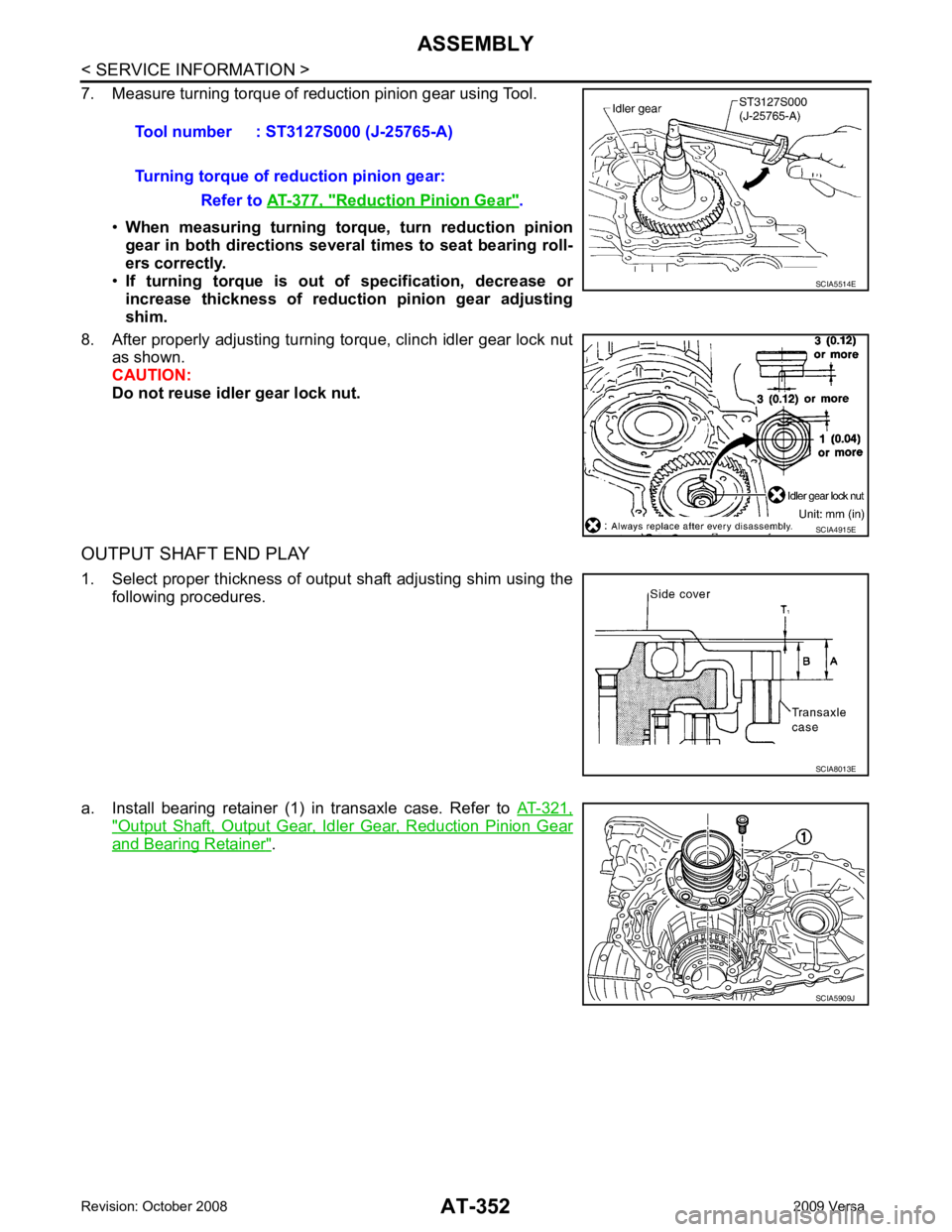
7. Measure turning torque of reduction pinion gear using Tool.
•When measuring turning torq ue, turn reduction pinion
gear in both directions several times to seat bearing roll-
ers correctly.
• If turning torque is out of specification, decrease or
increase thickness of reducti on pinion gear adjusting
shim.
8. After properly adjusting turning torque, clinch idler gear lock nut as shown.
CAUTION:
Do not reuse idler gear lock nut.
OUTPUT SHAFT END PLAY
1. Select proper thickness of output shaft adjusting shim using the following procedures.
a. Install bearing retainer (1) in transaxle case. Refer to AT-321," Output Shaft, Output Gear, Idler Gear, Reduction Pinion Gear
and Bearing Retainer " .
Tool number : ST3127S000 (J-25765-A)
Turning torque of reduction pinion gear: Refer to AT-377, " Reduction Pinion Gear " .
SCIA5514E
SCIA4915E
SCIA8013E
SCIA5909J
Page 358 of 4331
AT
N
O P
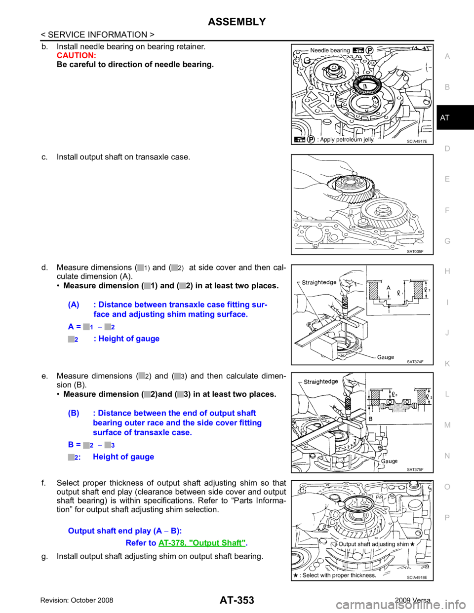
b. Install needle bearing on bearing retainer.
CAUTION:
Be careful to directio n of needle bearing.
c. Install output shaft on transaxle case.
d. Measure dimensions ( 1) and ( 2) at side cover and then cal-
culate dimension (A).
• Measure dimension ( 1) and ( 2) in at least two places.
e. Measure dimensions ( 2) and ( 3) and then calculate dimen-
sion (B).
• Measure dimension ( 2)and ( 3) in at least two places.
f. Select proper thickness of output shaft adjusting shim so that output shaft end play (clearance between side cover and output
shaft bearing) is within specificat ions. Refer to “Parts Informa-
tion” for output shaft adjusting shim selection.
g. Install output shaft adjusting shim on output shaft bearing. SAT035F
Output Shaft " .
Page 359 of 4331
" Component " .
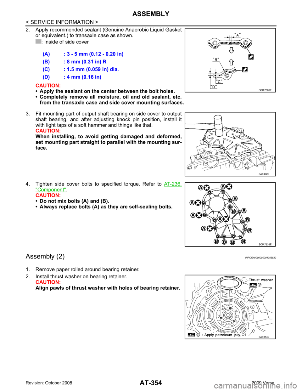
CAUTION:
• Do not mix bolts (A) and (B).
• Always replace bolts (A) as they are self-sealing bolts.
Assembly (2) INFOID:0000000004305530
1. Remove paper rolled around bearing retainer.
2. Install thrust washer on bearing retainer. CAUTION:
Align pawls of thrust washer wi th holes of bearing retainer.
(A) : 3 - 5 mm (0.12 - 0.20 in)
(B) : 8 mm (0.31 in) R
(C) : 1.5 mm (0.059 in) dia.
(D) : 4 mm (0.16 in) SAT442D
SAT354D
Page 360 of 4331
ASSEMBLY
AT-355
< SERVICE INFORMATION >
D
E
F
G H
I
J
K L
M A
B AT
N
O P
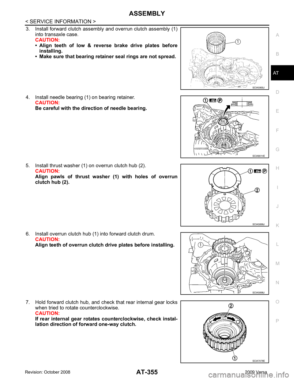
3. Install forward clutch assembly and overrun clutch assembly (1)
into transaxle case.
CAUTION:
• Align teeth of low & r everse brake drive plates before
installing.
• Make sure that bearing retain er seal rings are not spread.
4. Install needle bearing (1) on bearing retainer. CAUTION:
Be careful with the dir ection of needle bearing.
5. Install thrust washer (1) on overrun clutch hub (2). CAUTION:
Align pawls of thrust washer (1) with holes of overrun
clutch hub (2).
6. Install overrun clutch hub (1) into forward clutch drum. CAUTION:
Align teeth of overrun clutch drive plates before installing.
7. Hold forward clutch hub, and check that rear internal gear locks when tried to rotate counterclockwise.
CAUTION:
If rear internal gear rotates counterclockwise, check instal-
lation direction of fo rward one-way clutch. SCIA5900J
SCIA8014E
SCIA5899J
SCIA5898J
SCIA7078E