NISSAN LATIO 2009 Service Repair Manual
LATIO 2009
NISSAN
NISSAN
https://www.carmanualsonline.info/img/5/57359/w960_57359-0.png
NISSAN LATIO 2009 Service Repair Manual
Trending: length, warning, battery replacement, maintenance schedule, trailer, key, jump start
Page 621 of 4331
Page 622 of 4331
BL
N
O P
REAR DOOR
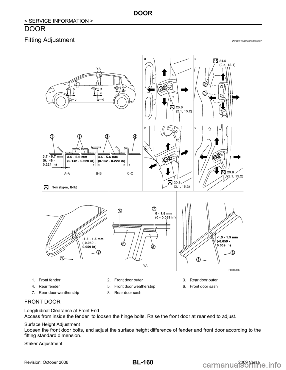
Longitudinal Clearance and Surface Height Adjustment at Front End 1. Remove the center pillar upper and lower garnishes. Refer to EI-39 .
2. Access from inside the vehicle to loosen the hinge nuts. Open the rear door, and raise the rear door at
rear end to adjust.
Surface Height Adjustment Loosen the front door striker bolts and rear door hinge nu ts, and adjust the surface height difference of front
and rear doors according to the fitting standard dimension.
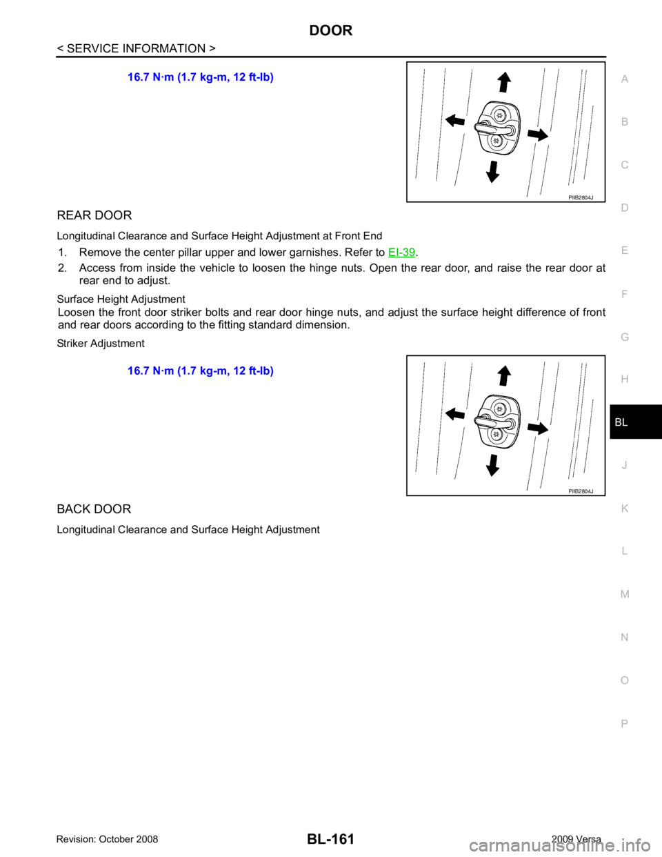
Striker Adjustment
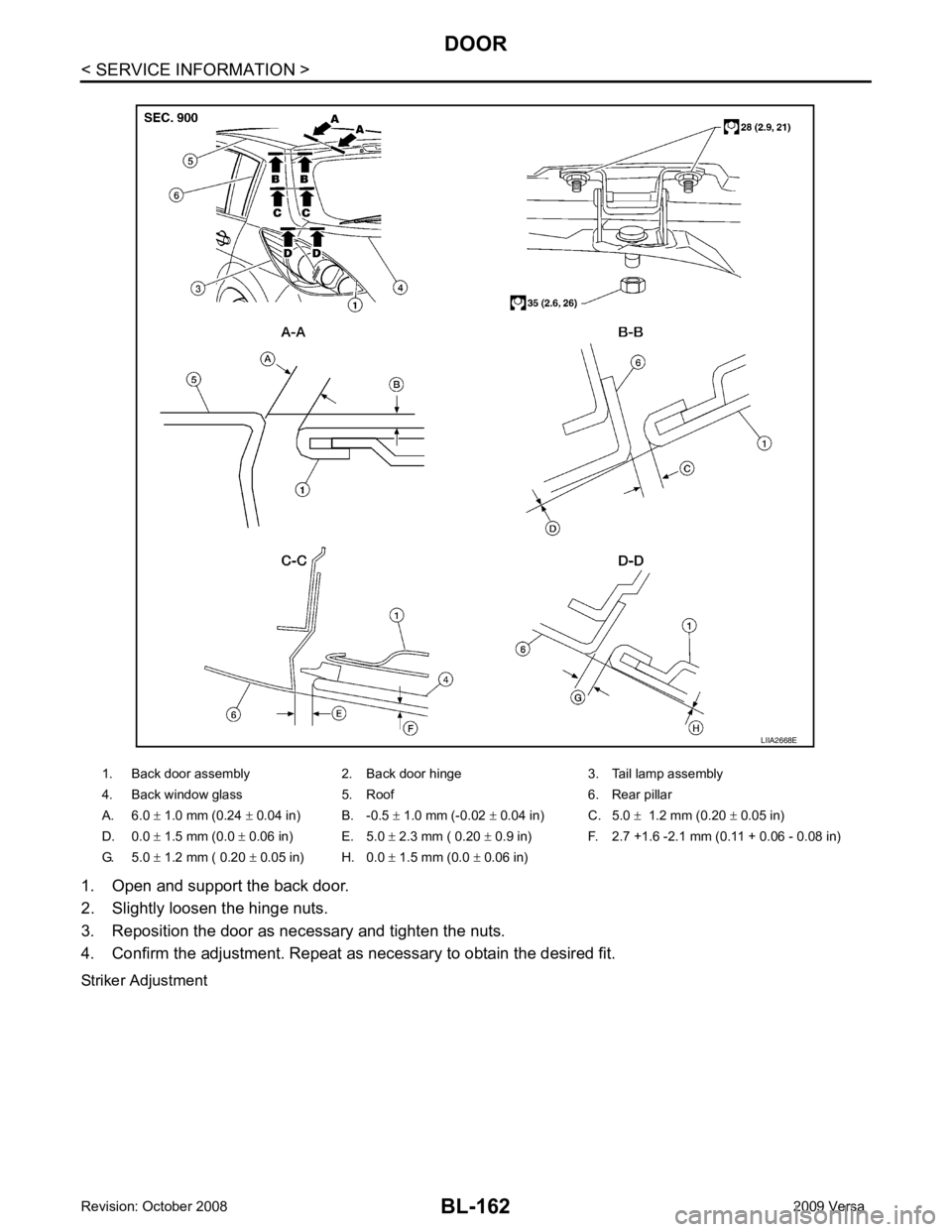
BACK DOOR
Longitudinal Clearance and Surface Height Adjustment 16.7 N·m (1.7 kg-m, 12 ft-lb)
Page 623 of 4331
Page 624 of 4331
BL
N
O P
Removal and Installation
INFOID:0000000004305078
FRONT DOOR CAUTION:
• When removing and installing the front door assembly, support the door with a jack and cloth to pro-
tect the door and body.
• When removing and installing front door assembly, be sure to carry out the fitting adjustment. Refer
to BL-160, " Fitting Adjustment " .
• After installing, apply touch-up pain t onto the head of the hinge nuts.
• Check the hinge rotating pa rt for lubrication. If necessary, apply “body grease”.
• Operate with two workers, because of its heavy weight.
• Check front door open/close op eration after installation.
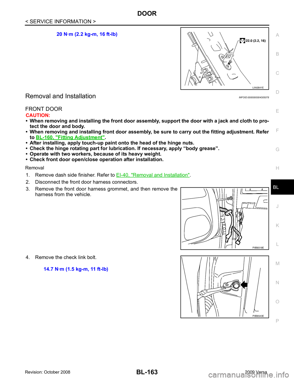
Removal 1. Remove dash side finisher. Refer to EI-40, " Removal and Installation " .
2. Disconnect the front door harness connectors.
3. Remove the front door harness grommet, and then remove the harness from the vehicle.
4. Remove the check link bolt. 20 N·m (2.2 kg-m, 16 ft-lb)
Page 625 of 4331
Fitting Adjustment " .
• After installing, apply touch-up pain t onto the head of the hinge nuts.
• Check the hinge rotating part for poor lubrication. If necessary, apply “body grease”.
• Operate with two workers, because of its heavy weight.
• Check rear door open/close op eration after installation.
Removal
1. Remove the rear door harness grommet.
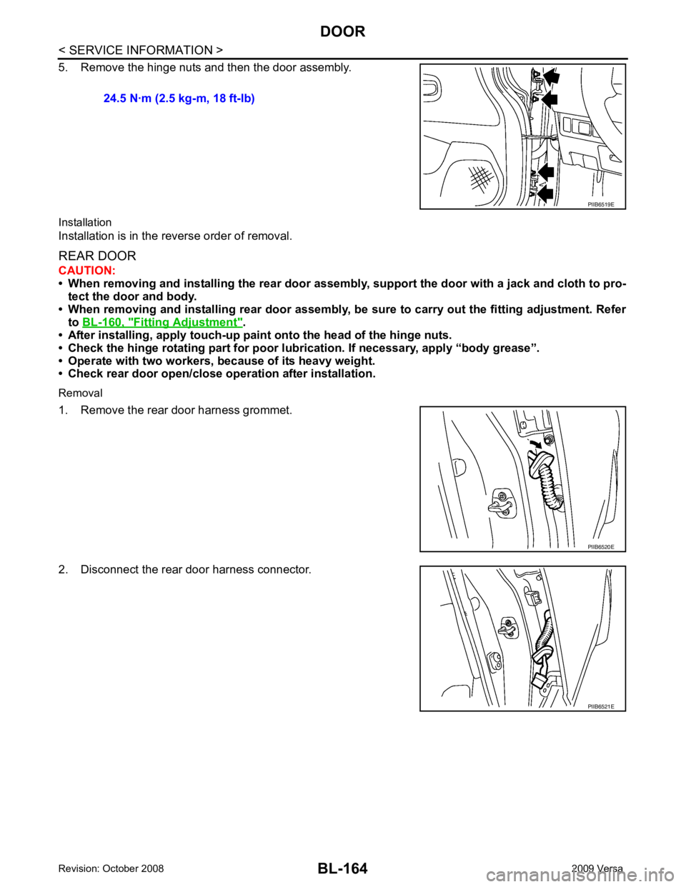
2. Disconnect the rear door harness connector. 24.5 N·m (2.5 kg-m, 18 ft-lb)
PIIB6521E
Page 626 of 4331
BL
N
O P
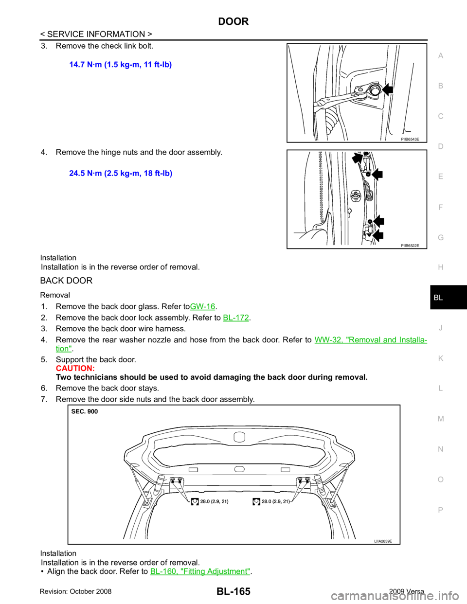
3. Remove the check link bolt.
4. Remove the hinge nuts and the door assembly.
Installation Installation is in the reverse order of removal.
BACK DOOR
Removal 1. Remove the back door glass. Refer to GW-16 .
2. Remove the back door lock assembly. Refer to BL-172 .
3. Remove the back door wire harness.
4. Remove the rear washer nozzle and hose from the back door. Refer to WW-32, " Removal and Installa-
tion " .
5. Support the back door. CAUTION:
Two technicians should be used to avoid damaging the back door during removal.
6. Remove the back door stays.
7. Remove the door side nuts and the back door assembly.
Installation Installation is in the reverse order of removal.
• Align the back door. Refer to BL-160, " Fitting Adjustment " .
14.7 N·m (1.5 kg-m, 11 ft-lb)
Page 627 of 4331
Removal and Installation " .
2. Fully close front door window.
3. Remove the front door sealing screen. NOTE:
If sealing screen is reused, cut butyl tape in a way that leaves it on the sealing screen.
4. Remove front door rear glass run channel. Refer to GW-44, " Removal and Installation " .
5. Remove the cables from the holder.
6. Remove inside handle bolt, and slide the handle toward the rear of the vehicle.
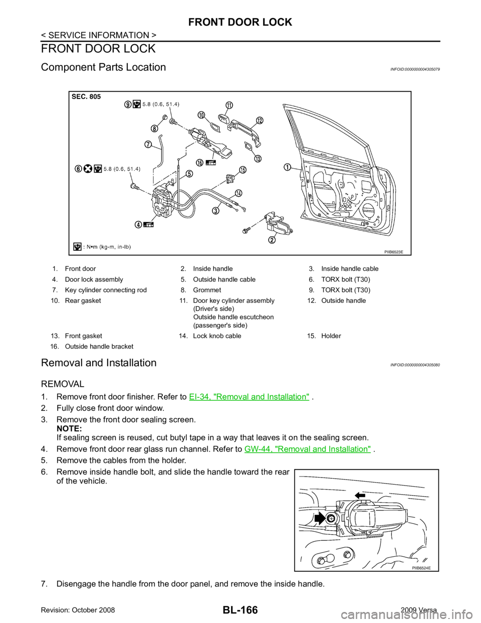
7. Disengage the handle from the door panel, and remove the inside handle. 1. Front door 2. Inside handle 3. Inside handle cable
4. Door lock assembly 5. Outside handle cable 6. TORX bolt (T30)
7. Key cylinder connecting rod 8. Grommet 9. TORX bolt (T30)
10. Rear gasket 11. Door key cylinder assembly (Driver's side)
Outside handle escutcheon
(passenger's side) 12. Outside handle
13. Front gasket 14. Lock knob cable 15. Holder
16. Outside handle bracket PIIB6524E
Page 628 of 4331
BL
N
O P
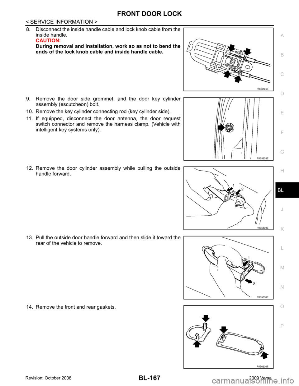
8. Disconnect the inside handle cable and lock knob cable from the
inside handle.
CAUTION:
During removal and installation , work so as not to bend the
ends of the lock knob cable and inside handle cable.
9. Remove the door side grommet, and the door key cylinder assembly (escutcheon) bolt.
10. Remove the key cylinder connecting rod (key cylinder side).
11. If equipped, disconnect the door antenna, the door request switch connector and remove the harness clamp. (Vehicle with
intelligent key systems only).
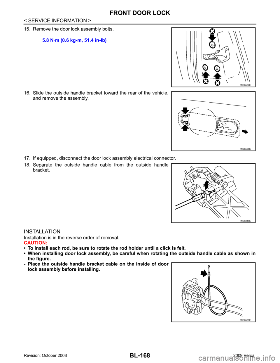
12. Remove the door cylinder assembly while pulling the outside handle forward.
13. Pull the outside door handle forward and then slide it toward the rear of the vehicle to remove.
14. Remove the front and rear gaskets. PIIB5808E
PIIB5809E
PIIB6526E
Page 629 of 4331
PIIB6528E
PIIB5815E
PIIB6529E
Page 630 of 4331
BL
N
O P
REAR DOOR LOCK
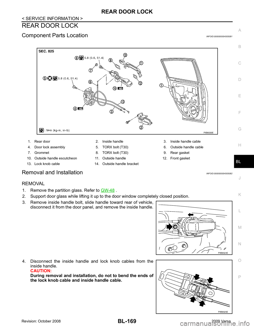
Component Parts Location INFOID:0000000004305081
Removal and Installation INFOID:0000000004305082
REMOVAL 1. Remove the partition glass. Refer to GW-48 .
2. Support door glass while lifting it up to the door window completely closed position.
3. Remove inside handle bolt, slide handle toward rear of vehicle, disconnect it from the door panel, and remove the inside handle.
4. Disconnect the inside handle and lock knob cables from the inside handle.
CAUTION:
During removal and installation, do not to bend the ends of
the lock knob cable and inside handle cable.
1. Rear door 2. Inside handle 3. Inside handle cable
4. Door lock assembly 5. TORX bolt (T30) 6. Outside handle cable
7. Grommet 8. TORX bolt (T30) 9. Rear gasket
10. Outside handle escutcheon 11. Outside handle 12. Front gasket
13. Lock knob cable 14. Outside handle bracket PIIB6525E
Trending: navigation system, warning light, horn, gas type, hood open, belt, oil additives
