NISSAN LATIO 2009 Service Repair Manual
Manufacturer: NISSAN, Model Year: 2009, Model line: LATIO, Model: NISSAN LATIO 2009Pages: 4331, PDF Size: 58.04 MB
Page 661 of 4331
BL-200< SERVICE INFORMATION >
TRUNK LID OPENER
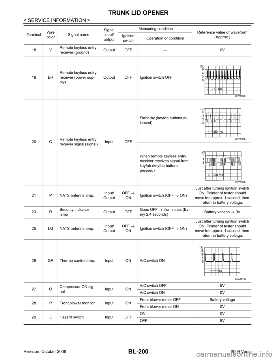
18 V Remote keyless entry
receiver (ground) Output OFF — 0V
19 BR Remote keyless entry
receiver (power sup-
ply) Output OFF Ignition switch OFF
20 G Remote keyless entry
receiver signal (signal) Input OFFStand-by (keyfob buttons re-
leased)
When remote keyless entry
receiver receives signal from
keyfob (keyfob buttons
pressed)
21 P NATS antenna amp. Input/
Output OFF
→
ON Ignition switch (OFF
→ ON) Just after turning ignition switch
ON: Pointer of tester should
move for approx. 1 second, then return to battery voltage.
23 R Security indicator
lamp Output OFFGoes OFF
→ illuminates (Ev-
ery 2.4 seconds) Battery voltage
→ 0V
25 LG NATS antenna amp. Input/
Output OFF
→
ON Ignition switch (OFF
→ ON) Just after turning ignition switch
ON: Pointer of tester should
move for approx. 1 second, then
return to battery voltage.
26 GR Thermo control amp. Input ON A/C switch ON
27 O Compressor ON sig-
nal Input ONA/C switch OFF 5V
A/C switch ON 0V
28 P Front blower monitor Input ON Front blower motor OFF Battery voltage
Front blower motor ON 0V
29 L Hazard switch Input OFF ON 0V
OFF 5V
Terminal
Wire
color Signal name Signal
input/
output Measuring condition
Reference value or waveform
(Approx.)
Ignition
switch Operation or condition LIIA1893E
LIIA1894E
LIIA1895E
ZJIA0719J
Page 662 of 4331
TRUNK LID OPENER
BL-201
< SERVICE INFORMATION >
C
D E
F
G H
J
K L
M A
B BL
N
O P
30
1
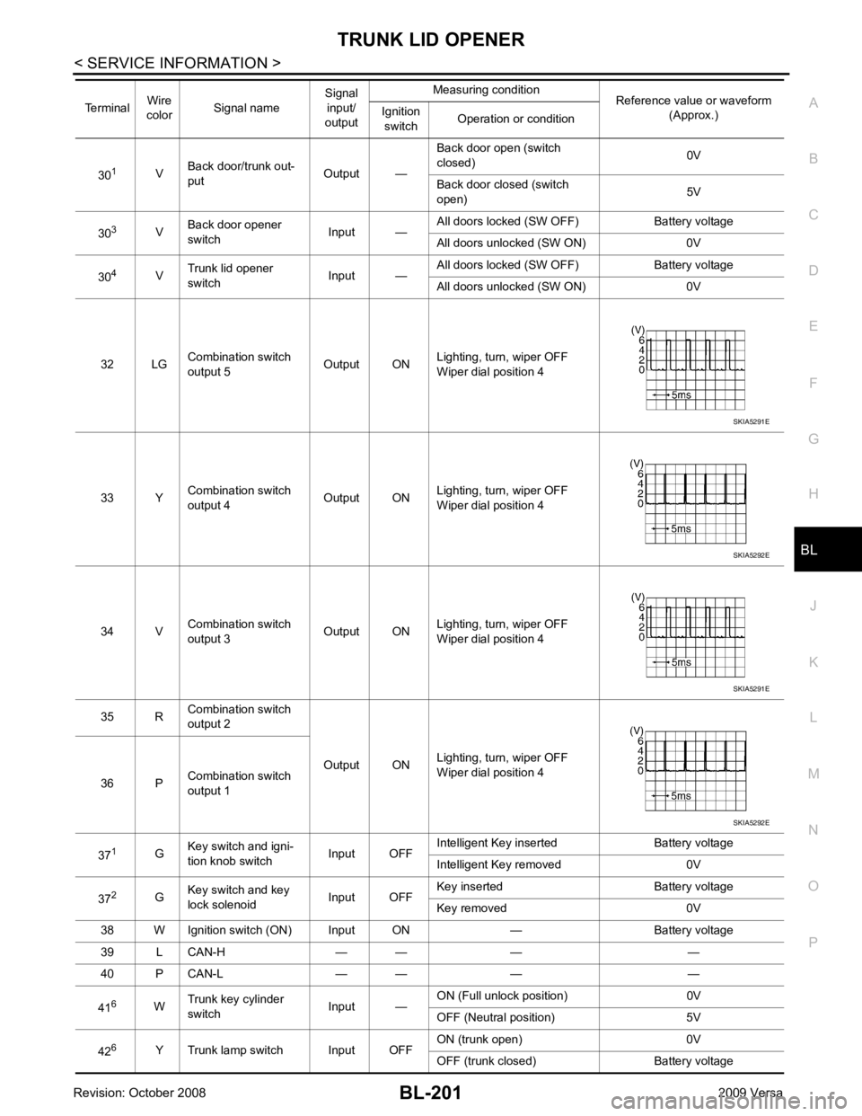
VBack door/trunk out-
put Output —Back door open (switch
closed) 0V
Back door closed (switch
open) 5V
30 3
VBack door opener
switch Input —All doors locked (SW OFF) Battery voltage
All doors unlocked (SW ON) 0V
30 4
VTrunk lid opener
switch Input —All doors locked (SW OFF) Battery voltage
All doors unlocked (SW ON) 0V
32 LG Combination switch
output 5 Output ONLighting, turn, wiper OFF
Wiper dial position 4
33 Y Combination switch
output 4 Output ON
Lighting, turn, wiper OFF
Wiper dial position 4
34 V Combination switch
output 3 Output ONLighting, turn, wiper OFF
Wiper dial position 4
35 R Combination switch
output 2
Output ONLighting, turn, wiper OFF
Wiper dial position 4
36 P Combination switch
output 1
37 1
GKey switch and igni-
tion knob switch Input OFFIntelligent Key inserted Battery voltage
Intelligent Key removed 0V
37 2
GKey switch and key
lock solenoid Input OFFKey inserted Battery voltage
Key removed 0V
38 W Ignition switch (ON) Input ON — Battery voltage
39 L CAN-H — — — —
40 P CAN-L — — — —
41 6
WTrunk key cylinder
switch Input —ON (Full unlock position) 0V
OFF (Neutral position) 5V
42 6
Y Trunk lamp switch Input OFF ON (trunk open) 0V
OFF (trunk closed) Battery voltage
Terminal
Wire
color Signal name Signal
input/
output Measuring condition
Reference value or waveform
(Approx.)
Ignition
switch Operation or condition SKIA5291E
SKIA5292E
SKIA5291E
SKIA5292E
Page 663 of 4331

BL-202< SERVICE INFORMATION >
TRUNK LID OPENER
43 5
R Back door switch Input OFF ON (open) 0V
OFF (closed) Ba ttery voltage
44 5
LG Rear wiper auto stop Input ON Rear wiper operating 0
Rear wiper stopped Battery
45 7
GR Lock switch Input OFF ON (lock) 0V
OFF Battery voltage
46 7
L Unlock switch Input OFF ON (unlock) 0V
OFF Battery voltage
47 BR Front door switch LH Input OFF ON (open) 0V
OFF (closed) Ba ttery voltage
48 O Rear door switch LH Input OFF ON (open) 0V
OFF (closed) Ba ttery voltage
49 P Luggage room lamp Output OFF Any door open (ON) 0V
All doors closed (OFF) Battery voltage
50 SB A/C indicator Output ON A/C OFF 0
A/C ON Battery voltage
53 5
RBack door lock assem-
bly (actuator) Output OFF Back door (open) Battery voltage
53 6
RTrunk lamp switch and
trunk release solenoid Output OFF Trunk lid (open) Battery voltage
55 5
VRear wiper motor out-
put Output ONOFF 0
ON Battery voltage
56 R Battery saver output Output OFF
30 minutes after ignition
switch is turned OFF 0V
ON — Battery voltage
57 LG Battery power supply Input OFF — Battery voltage
59 7
GFront door lock actua-
tor LH (unlock) Output OFFOFF (neutral) 0V
ON (unlock) Battery voltage
60 V Turn signal (left) Output ON Turn left ON
61 W Turn signal (right) Output ON Turn right ON
63 BR Interior room lamp Output OFF Any door
switch ON (open) 0V
OFF (closed) Battery voltage
Terminal
Wire
color Signal name Signal
input/
output Measuring condition
Reference value or waveform
(Approx.)
Ignition
switch Operation or condition SKIA3009J
SKIA3009J
Page 664 of 4331

BL
N
O P
1: With Intelligent Key
2: Without Intelligent Key
3: Hatchback without Intelligent Key
4: Sedan without Intelligent Key
5: Hatchback
6: Sedan
7: With power door locks
8: With power windows
Terminal and Reference Valu e for Intelligent Key Unit INFOID:0000000004678894
65
7
SBAll door lock actuators
(lock) Output OFFOFF (neutral) 0V
ON (lock) Battery voltage
66 7
GFront door lock actua-
tor RH, rear door lock
actuators LH/RH (un-
lock) Output OFFOFF (neutral) 0V
ON (unlock) Battery voltage
67 B Ground Input ON — 0V
68 8
LPower window power
supply (RAP) Output —Ignition switch ON Battery voltage
Within 45 seconds after igni-
tion switch OFF Battery voltage
More than 45 seconds after ig-
nition switch OFF 0V
When front door LH or RH is
open or power window timer
operates 0V
69 8
P Battery power supply
OutputOFF
— Battery voltage
70 Y Battery power supply Input OFF — Battery voltage
Terminal
Wire
color Signal name Signal
input/
output Measuring condition
Reference value or waveform
(Approx.)
Ignition
switch Operation or condition Terminal
Wire
Color Item Condition
Voltage (V)Approx.
Ignition
Switch
Position Operation or Conditions
1 R Steering lock solenoid
power supply LOCK — 5
2 L CAN-H — — —
3 P CAN-L — — —
4 O Intelligent Key warning
buzzer LOCKOperate door request
switch. Buzzer OFF Battery voltage
Sound buzzer 0
5 G Front door request
switch LH —Press door request switch (driver side). 0
Other than above 5
6 Y Ignition switch (ON) ON — Battery voltage
7 LG Key switch LOCK Insert mechanical key into ignition switch. Battery voltage
Remove mechanical key from ignition
switch. 0
10 *1
WCVT or A/T device
(park position switch) ONShift lever in park position. 0
Other than above Battery voltage
11 SB Power source (Fus e) — — Battery voltage
12 B Ground — — 0
Page 665 of 4331
BL-204< SERVICE INFORMATION >
TRUNK LID OPENER
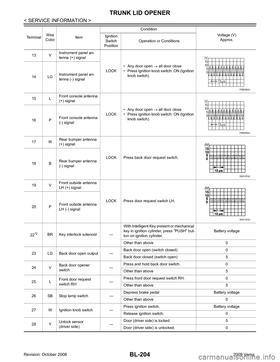
13 V Instrument panel an-
tenna (+) signal
LOCK• Any door open
→ all door close
• Press ignition knob switch: ON (Ignition knob switch)
14 LG Instrument panel an-
tenna (-) signal
15 L Front console antenna
(+) signal
LOCK• Any door open
→ all door close
• Press ignition knob switch: ON (Ignition knob switch)
16 P Front console antenna
(-) signal
17 W Rear bumper antenna
(+) signal
LOCK Press back door request switch.
18 B Rear bumper antenna
(-) signal
19 V Front outside antenna
LH (+) signal
LOCK Press door request switch LH.
20 P Front outside antenna
LH (-) signal
22 *2
BR Key interlock solenoid — With Intelligent Key present or mechanical
key in ignition cylinder, press "PUSH" but-
ton on ignition cylinder. Battery voltage
Other than above 0
23 LG Back door open output — Back door open (switch closed) 0
Back door closed (switch open) 5
24 V Back door opener
switch —Press and hold back door switch. 0
Other than above 5
25 L Front door request
switch RH —Press front door request switch RH. 0
Other than above 5
26 SB Stop lamp switch — Depress brake pedal Battery voltage
Other than above 0
27 W Ignition knob switch — Press ignition switch. Battery voltage
Release ignition switch. 0
28 Y Unlock sensor
(driver side) —Door (driver si
de) is locked. 5
Door (driver side ) is unlocked. 0
Terminal
Wire
Color Item Condition
Voltage (V)Approx.
Ignition
Switch
Position Operation or Conditions PIIB5502J
PIIB5502J
SIIA1910J
SIIA1910J
Page 666 of 4331
TRUNK LID OPENER
BL-205
< SERVICE INFORMATION >
C
D E
F
G H
J
K L
M A
B BL
N
O P
*1: With continuously variable transmission (CVT) or automatic transmission (A/T).
*2: With manual transmission (M/T).
CONSULT-III Function (BCM) INFOID:0000000004305106
CONSULT-III can display each diagnostic item using the diagnostic test modes shown following. 29 V
Back door request
switch (hatchback) —Press back door request switch. 0
Other than above 5
Trunk opener request
switch (sedan) —Press trunk opener request switch. 0
Other than above 5
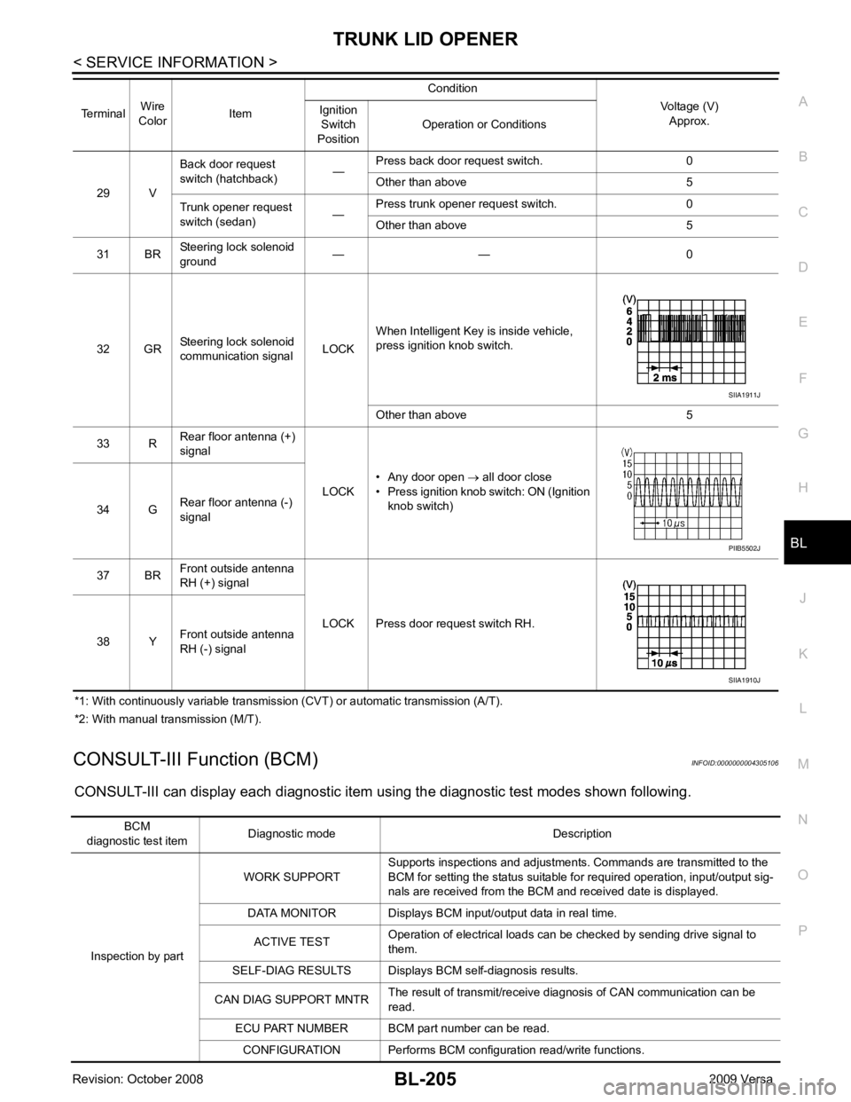
31 BR Steering lock solenoid
ground — — 0
32 GR Steering lock solenoid
communication signal LOCKWhen Intelligent Key is inside vehicle,
press ignition knob switch.
Other than above 5
33 R Rear floor antenna (+)
signal
LOCK• Any door open
→ all door close
• Press ignition knob switch: ON (Ignition
knob switch)
34 G Rear floor antenna (-)
signal
37 BR Front outside antenna
RH (+) signal
LOCK Press door request switch RH.
38 Y Front outside antenna
RH (-) signal
Terminal
Wire
Color Item Condition
Voltage (V)Approx.
Ignition
Switch
Position Operation or Conditions SIIA1911J
PIIB5502J
SIIA1910J
BCM
diagnostic test item Diagnostic mode Description
Inspection by part WORK SUPPORT
Supports inspections and adjustments. Commands are transmitted to the
BCM for setting the status suitable for required operation, input/output sig-
nals are received from the BCM and received date is displayed.
DATA MONITOR Displays BCM input/output data in real time.
ACTIVE TEST Operation of electrical loads can be checked by sending drive signal to
them.
SELF-DIAG RESULTS Displays BC M self-diagnosis results.
CAN DIAG SUPPORT MNTR The result of transmit/receive diagnosis of CAN communication can be
read.
ECU PART NUMBER BCM part number can be read.
CONFIGURATION Performs BCM configuration read/write functions.
Page 667 of 4331

System Description " .
3. Repair or replace any malfunctioning parts. Refer to BL-206, " Trouble Diagnosis Chart by Symptom " .
4. Does trunk lid opener operate normally? If Yes, GO TO 5. If No, GO TO 3.
5. Inspection End.
Trouble Diagnosis Chart by Symptom INFOID:0000000004305108
BCM Power Supply and Gr ound Circuit Inspection INFOID:0000000004678899Test item Content
TRUNK/BACK DOOR This test is able to check trunk lid lock assembly (actuator) unlock operation.
Actuator opens trunk lid lock assembly when “OPEN” on CONSULT-III screen is touched. Symptom Diagnoses/service procedure
Reference
page
Trunk lid opener does not operate.
(Without Intelligent Key or power windows) 1. Check BCM power supply and ground circuit.
BCS-15 2. Check trunk lid opener switch circuit.
BL-207 3. Check trunk lid lock assembly (actuator) circuit.
BL-214 4. Replace BCM.
BCS-18Trunk lid opener does not operate.
(Without Intelligent Key, with power windows) 1. Check BCM power supply and ground circuit.
BCS-15 2. Check trunk lid opener switch circuit.
BL-210 3. Check trunk lid lock assembly (actuator) circuit.
BL-214 4. Replace BCM.
BCS-18Trunk lid opener does not operate.
(With Intelligent Key) 1. Check BCM power supply and ground circuit.
BCS-15 2.
Check Intelligent Key power supply and ground cir-
cuit. BL-126 3. Check trunk lid opener switch circuit.
BL-212 4. Check trunk lid lock assembly (actuator) circuit.
BL-214 5. Replace BCM.
BCS-18
Page 668 of 4331
TRUNK LID OPENER
BL-207
< SERVICE INFORMATION >
C
D E
F
G H
J
K L
M A
B BL
N
O P
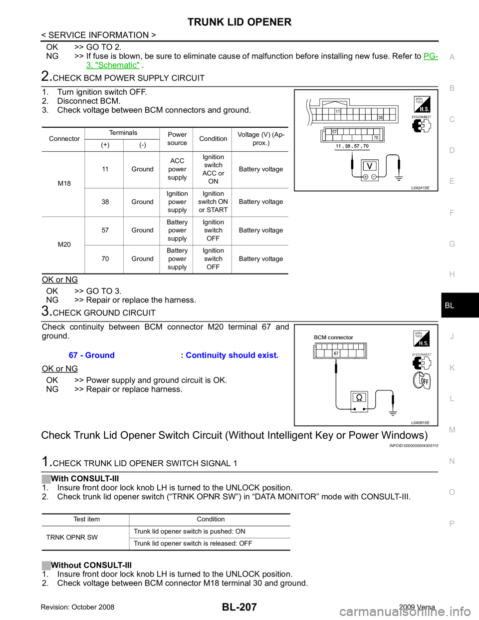
OK >> GO TO 2.
NG >> If fuse is blown, be sure to eliminate caus e of malfunction before installing new fuse. Refer to PG-3, " Schematic " .
2.
CHECK BCM POWER SUPPLY CIRCUIT
1. Turn ignition switch OFF.
2. Disconnect BCM.
3. Check voltage between BCM connectors and ground.
OK or NG OK >> GO TO 3.
NG >> Repair or replace the harness. 3.
CHECK GROUND CIRCUIT
Check continuity between BCM connector M20 terminal 67 and
ground.
OK or NG OK >> Power supply and ground circuit is OK.
NG >> Repair or replace harness.
Check Trunk Lid Opener Switch Circuit (Wit hout Intelligent Key or Power Windows)
INFOID:00000000043051101.
CHECK TRUNK LID OPENER SWITCH SIGNAL 1
With CONSULT-III
1. Insure front door lock knob LH is turned to the UNLOCK position.
2. Check trunk lid opener switch (“TRNK OPNR SW”) in “DATA MONITOR” mode with CONSULT-III.
Without CONSULT-III
1. Insure front door lock knob LH is turned to the UNLOCK position.
2. Check voltage between BCM connector M18 terminal 30 and ground. Connector
Terminals
Power
source Condition Voltage (V) (Ap-
prox.)
(+) (-)
M18 11 Ground
ACC
power
supply Ignition
switch
ACC or ON Battery voltage
38 Ground Ignition
power
supply Ignition
switch ON
or START Battery voltage
M20 57 Ground
Battery
power
supply Ignition
switch OFF Battery voltage
70 Ground Battery
power
supply Ignition
switch OFF Battery voltage LIIA2415E
67 - Ground : Continuity should exist.
LIIA0915E
Test item Condition
TRNK OPNR SW Trunk lid opener switch is pushed: ON
Trunk lid opener switch is released: OFF
Page 669 of 4331
BL-208< SERVICE INFORMATION >
TRUNK LID OPENER
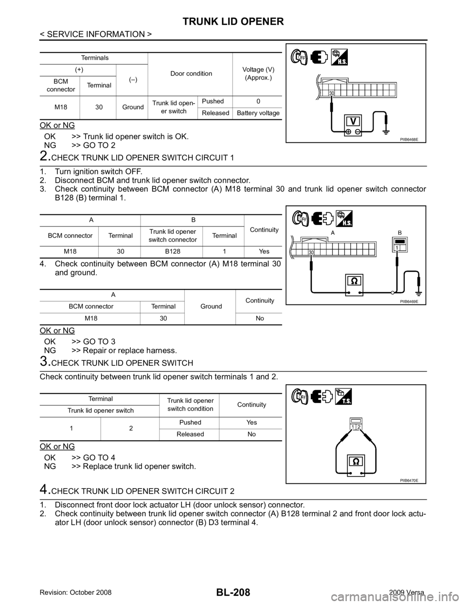
OK or NG OK >> Trunk lid opener switch is OK.
NG >> GO TO 2 2.
CHECK TRUNK LID OPENER SWITCH CIRCUIT 1
1. Turn ignition switch OFF.
2. Disconnect BCM and trunk lid opener switch connector.
3. Check continuity between BCM connector (A) M18 terminal 30 and trunk lid opener switch connector
B128 (B) terminal 1.
4. Check continuity between BCM connector (A) M18 terminal 30
and ground.
OK or NG OK >> GO TO 3
NG >> Repair or replace harness. 3.
CHECK TRUNK LID OPENER SWITCH
Check continuity between trunk lid opener switch terminals 1 and 2.
OK or NG OK >> GO TO 4
NG >> Replace trunk lid opener switch. 4.
CHECK TRUNK LID OPENER SWITCH CIRCUIT 2
1. Disconnect front door lock actuator LH (door unlock sensor) connector.
2. Check continuity between trunk lid opener switch connector (A) B128 terminal 2 and front door lock actu- ator LH (door unlock sensor) connector (B) D3 terminal 4. Terminals
Door conditionVoltage (V)
(Approx.)
(+)
(–)
BCM
connector Terminal
M18 30 Ground Trunk lid open-
er switch Pushed 0
Released Battery voltage PIIB6468E
A B
Continuity
BCM connector Terminal Trunk lid opener
switch connector Terminal
M18 30 B128 1 Yes
A GroundContinuity
BCM connector Terminal
M18 30 No PIIB6469E
Terminal
Trunk lid opener
switch condition Continuity
Trunk lid opener switch
1 2 Pushed Yes
Released No PIIB6470E
Page 670 of 4331
TRUNK LID OPENER
BL-209
< SERVICE INFORMATION >
C
D E
F
G H
J
K L
M A
B BL
N
O P
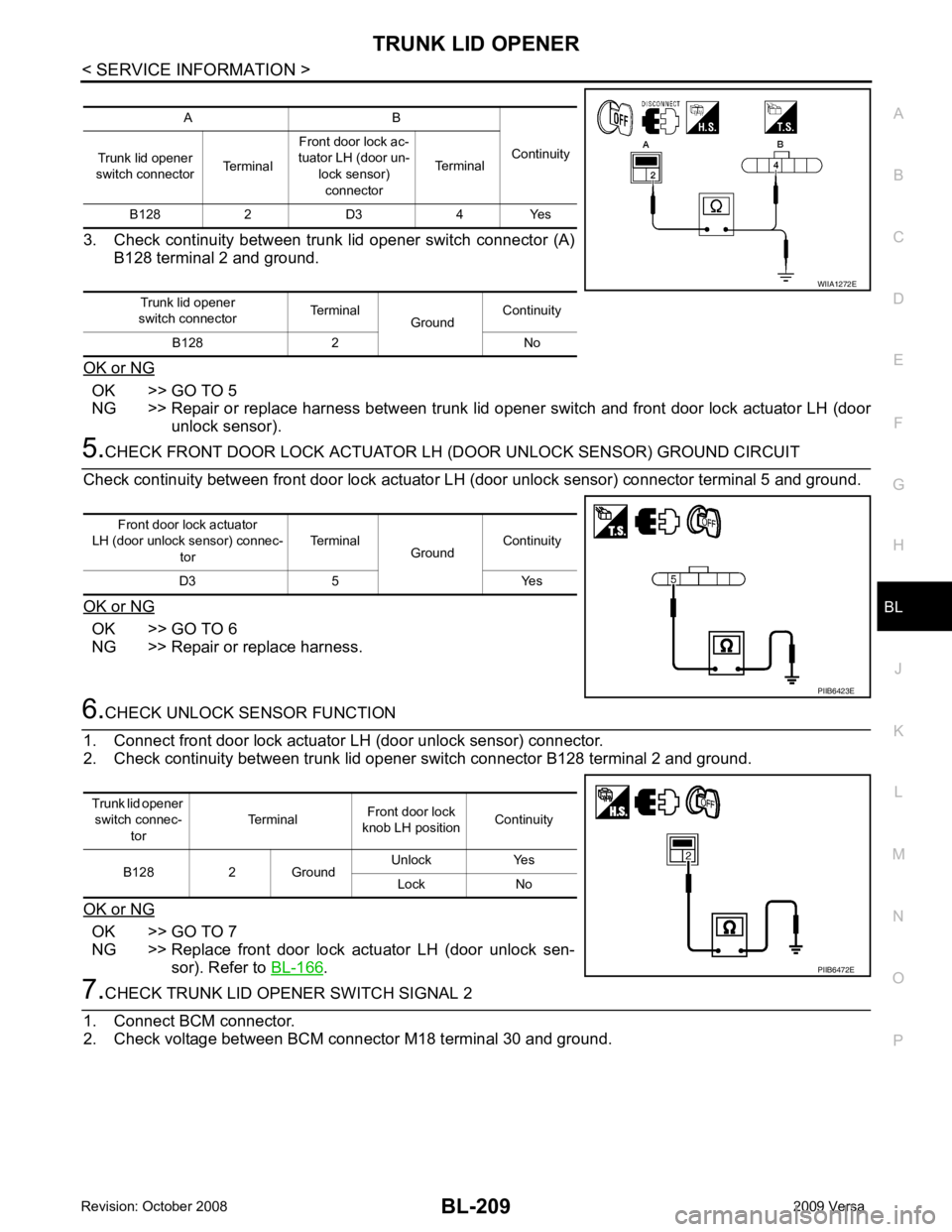
3. Check continuity between trunk lid opener switch connector (A)
B128 terminal 2 and ground.
OK or NG OK >> GO TO 5
NG >> Repair or replace harness between trunk lid opener switch and front door lock actuator LH (door
unlock sensor). 5.
CHECK FRONT DOOR LOCK ACTUATOR LH (DOOR UNLOCK SENSOR) GROUND CIRCUIT
Check continuity between front door lock actuator LH (door unlock sensor) connector terminal 5 and ground.
OK or NG OK >> GO TO 6
NG >> Repair or replace harness. 6.
CHECK UNLOCK SENSOR FUNCTION
1. Connect front door lock actuator LH (door unlock sensor) connector.
2. Check continuity between trunk lid opener switch connector B128 terminal 2 and ground.
OK or NG OK >> GO TO 7
NG >> Replace front door lock actuator LH (door unlock sen- sor). Refer to BL-166 .
7.
CHECK TRUNK LID OPENER SWITCH SIGNAL 2
1. Connect BCM connector.
2. Check voltage between BCM connector M18 terminal 30 and ground. A B
Continuity
Trunk lid opener
switch connector TerminalFront door lock ac-
tuator LH (door un-
lock sensor)connector Terminal
B128 2 D3 4 Yes
Trunk lid opener
switch connector Terminal
GroundContinuity
B128 2 No WIIA1272E
Front door lock actuator
LH (door unlock sensor) connec-
tor Terminal
GroundContinuity
D3 5 Yes PIIB6423E
Trunk lid opener
switch connec- tor Terminal
Front door lock
knob LH position Continuity
B128 2 Ground Unlock Yes
Lock No PIIB6472E