sensor NISSAN LATIO 2009 Service Repair Manual
[x] Cancel search | Manufacturer: NISSAN, Model Year: 2009, Model line: LATIO, Model: NISSAN LATIO 2009Pages: 4331, PDF Size: 58.04 MB
Page 2219 of 4331

EC
NP
O
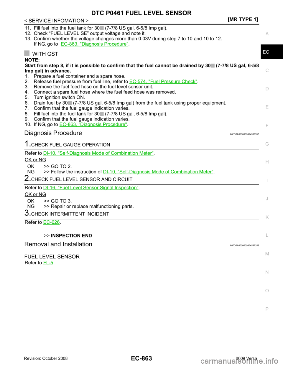
11. Fill fuel into the fuel tank for 30 (7-7/8 US gal, 6-5/8 Imp gal).
12. Check “FUEL LEVEL SE” output voltage and note it.
13. Confirm whether the voltage changes more than 0.03V during step 7 to 10 and 10 to 12. If NG, go to EC-863, " Diagnosis Procedure " .
WITH GST
NOTE:
Start from step 8, if it is possible to confirm that the fuel cannot be drained by 30 (7-7/8 US gal, 6-5/8
Imp gal) in advance.
1. Prepare a fuel container and a spare hose.
2. Release fuel pressure from fuel line, refer to EC-574, " Fuel Pressure Check " .
3. Remove the fuel feed hose on the fuel level sensor unit.
4. Connect a spare fuel hose where the fuel feed hose was removed.
5. Turn ignition switch ON.
6. Drain fuel by 30 (7-7/8 US gal, 6-5/8 Imp gal) from the fuel tank using proper equipment.
7. Confirm that the fuel gauge indication varies.
8. Fill fuel into the fuel tank for 30 (7-7/8 US gal, 6-5/8 Imp gal).
9. Confirm that the fuel gauge indication varies.
10. If NG, go to EC-863, " Diagnosis Procedure " .
Diagnosis Procedure INFOID:0000000004537357Self-Diagnosis Mode of Combination Meter " .
OK or NG OK >> GO TO 2.
NG >> Follow the instruction of DI-10, " Self-Diagnosis Mode of Combination Meter " .
Fuel Level Sensor Signal Inspection " .
OK or NG OK >> GO TO 3.
NG >> Repair or replace malfunctioning parts. .
>> INSPECTION END
Removal and Installation INFOID:0000000004537358
FUEL LEVEL SENSOR Refer to FL-5 .
Page 2220 of 4331
![NISSAN LATIO 2009 Service Repair Manual EC-864< SERVICE INFOMATION >
[MR TYPE 1]
DTC P0462, P0463
FUEL LEVEL SENSOR
DTC P0462, P0463 FUEL LEVEL SENSOR
Component Description INFOID:0000000004537359
The fuel level sensor (3) is mounted in t NISSAN LATIO 2009 Service Repair Manual EC-864< SERVICE INFOMATION >
[MR TYPE 1]
DTC P0462, P0463
FUEL LEVEL SENSOR
DTC P0462, P0463 FUEL LEVEL SENSOR
Component Description INFOID:0000000004537359
The fuel level sensor (3) is mounted in t](/img/5/57359/w960_57359-2219.png)
EC-864< SERVICE INFOMATION >
[MR TYPE 1]
DTC P0462, P0463
FUEL LEVEL SENSOR
DTC P0462, P0463 FUEL LEVEL SENSOR
Component Description INFOID:0000000004537359
The fuel level sensor (3) is mounted in the fuel level sensor unit. The
sensor detects a fuel level in the fuel tank and transmits a signal to
the combination meter. The combination meter. sends the fuel level
sensor signal to the ECM through CAN communication line.
It consists of two parts, one is mechanical float and the other is vari-
able resistor. Fuel level sensor output voltage changes depending on
the movement of the fuel mechanical float.
• Fuel level sensor unit and fuel pump (1)
• Fuel pressure regulator (2)
• Fuel tank temperature sensor (4)
On Board Diagn osis Logic INFOID:0000000004537360
NOTE:
• If DTC P0462 or P0463 is displayed with DTC U1000, U1001, first perform the trouble diagnosis for
DTC U1000, U1001. Refer to EC-633 .
• If DTC P0462 or P0463 is displayed with DTC U1010, first perform the trouble diagnosis for DTC
U1010. Refer to EC-635 .
DTC Confirmation Procedure INFOID:0000000004537361
NOTE:
If DTC Confirmation Procedure has been previously conduc ted, always turn ignition switch OFF and wait at
least 10 seconds before conducting the next test.
TESTING CONDITION:
Before performing the following procedure, confirm that battery voltage is more than 11V at ignition
switch ON.
1. Turn ignition switch ON and wait at least 5 seconds.
2. Check 1st trip DTC.
3. If 1st trip DTC is detected, go to EC-864, " Diagnosis Procedure " .
Diagnosis Procedure INFOID:00000000045373621.
CHECK FUEL GAUGE OPERATION
Refer to DI-10, " Self-Diagnosis Mode of Combination Meter " .
OK or NG OK >> GO TO 2.
NG >> Follow the instruction of DI-10, " Self-Diagnosis Mode of Combination Meter " .
2.
CHECK FUEL LEVEL SENSOR AND CIRCUIT
Refer to DI-16, " Fuel Level Sensor Signal Inspection " .
OK or NG OK >> GO TO 3.
NG >> Repair or replace malfunctioning parts. BBIA0704E
DTC No. Trouble diagnosis name DTC detecting condition Possible cause
P0462
0462 Fuel level sensor circuit
low input An excessively low voltage from the sensor is
sent to ECM. • Harness or connectors
(CAN communication line is open or
shorted)
• Harness or connectors
(Fuel level sensor circuit is open or short-
ed)
• Combination meter
• Fuel level sensor
P0463
0463 Fuel level sensor circuit
high input An excessively high voltage from the sensor is
sent to ECM.
Page 2221 of 4331

EC
NP
O .
>> INSPECTION END
Removal and Installation INFOID:0000000004537363
FUEL LEVEL SENSOR Refer to FL-5 .
Page 2222 of 4331

.
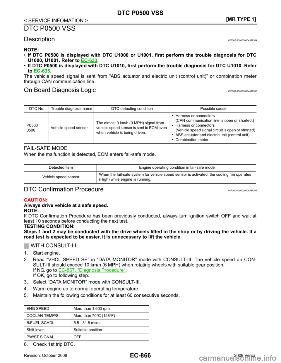
• If DTC P0500 is displayed with DTC U1010, first pe rform the trouble diagnosis for DTC U1010. Refer
to EC-635 .
The vehicle speed signal is sent from “ABS actuator and electric unit (control unit)” or combination meter
through CAN communication line.
On Board Diagn osis Logic INFOID:0000000004537365
FAIL-SAFE MODE
When the malfunction is detected, ECM enters fail-safe mode.
DTC Confirmation Procedure INFOID:0000000004537366
CAUTION:
Always drive vehicle at a safe speed.
NOTE:
If DTC Confirmation Procedure has been previously conduc ted, always turn ignition switch OFF and wait at
least 10 seconds before conducting the next test.
TESTING CONDITION:
Steps 1 and 2 may be conducted with the drive wheels li fted in the shop or by driving the vehicle. If a
road test is expected to be easier, it is unnecessary to lift the vehicle.
WITH CONSULT-III
1. Start engine.
2. Read “VHCL SPEED SE” in “DATA MONITOR” m ode with CONSULT-III. The vehicle speed on CON-
SULT-III should exceed 10 km/h (6 MPH) when rotating wheels with suitable gear position.
If NG, go to EC-867, " Diagnosis Procedure " .
If OK, go to following step.
3. Select “DATA MONITOR” mode with CONSULT-III.
4. Warm engine up to normal operating temperature.
5. Maintain the following conditions for at least 60 consecutive seconds.
6. Check 1st trip DTC. DTC No. Trouble diagnosis name DTC detecting condition Possible cause
P0500
0500 Vehicle speed sensor The almost 0 km/h (0 MPH) signal from
vehicle speed sensor is sent to ECM even
when vehicle is being driven. • Harness or connectors
(CAN communication line is open or shorted.)
• Harness or connectors (Vehicle speed signal circuit is open or shorted)
• ABS actuator and electric unit (control unit)
• Combination meter Detected item Engine operating condition in fail-safe mode
Vehicle speed sensor When the fail-safe system for vehicle speed sensor is activated, the cooling fan operates
(High) while engine is running. ENG SPEED More th
an 1,600 rpm
COOLAN TEMP/S More than 70 °C (158 °F)
B/FUEL SCHDL 5.5 - 31.8 msec
Shift lever Suitable position
PW/ST SIGNAL OFF
Page 2230 of 4331

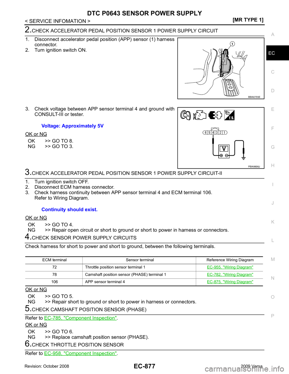
Diagnosis Procedure " .
DTC No.
Trouble diagnosis
name DTC detecting condition Possible cause
P0643
0643 Sensor power supply
circuit short ECM detects a voltage of power source for
sensor is excessively low or high. • Harness or connectors
(APP sensor 1 circuit is shorted.)
(Throttle position sensor circuit is shorted.)
[Camshaft position sensor (PHASE) circuit is
shorted.]
• Accelerator pedal position sensor
• Throttle position sensor
• Camshaft position sensor (PHASE) Engine operation condition in fail-safe mode
ECM stops the electric throttle control actuator control, throttle valve is maintained at a fixed opening (approx. 5 degrees) b y the return
spring.
Page 2231 of 4331
![NISSAN LATIO 2009 Service Repair Manual DTC P0643 SENSOR POWER SUPPLY
EC-875
< SERVICE INFOMATION >
[MR TYPE 1] C
D E
F
G H
I
J
K L
M A EC
NP
O
Wiring Diagram
INFOID:0000000004537383
Specification data are reference values and are measured NISSAN LATIO 2009 Service Repair Manual DTC P0643 SENSOR POWER SUPPLY
EC-875
< SERVICE INFOMATION >
[MR TYPE 1] C
D E
F
G H
I
J
K L
M A EC
NP
O
Wiring Diagram
INFOID:0000000004537383
Specification data are reference values and are measured](/img/5/57359/w960_57359-2230.png)
DTC P0643 SENSOR POWER SUPPLY
EC-875
< SERVICE INFOMATION >
[MR TYPE 1] C
D E
F
G H
I
J
K L
M A EC
NP
O
Wiring Diagram
INFOID:0000000004537383
Specification data are reference values and are measured between each terminal and ground.
CAUTION:
Do not use ECM ground terminals wh en measuring input/output voltage. Doing so may result in dam-
age to the ECM's transistor. Use a ground ot her than ECM terminals, such as the ground. BBWA2649E
Page 2232 of 4331
![NISSAN LATIO 2009 Service Repair Manual EC-876< SERVICE INFOMATION >
[MR TYPE 1]
DTC P0643 SENSOR POWER SUPPLY
Diagnosis Procedure INFOID:00000000045373841.
CHECK GROUND CONNECTIONS
1. Turn ignition switch OFF.
2. Loosen and retighten groun NISSAN LATIO 2009 Service Repair Manual EC-876< SERVICE INFOMATION >
[MR TYPE 1]
DTC P0643 SENSOR POWER SUPPLY
Diagnosis Procedure INFOID:00000000045373841.
CHECK GROUND CONNECTIONS
1. Turn ignition switch OFF.
2. Loosen and retighten groun](/img/5/57359/w960_57359-2231.png)
EC-876< SERVICE INFOMATION >
[MR TYPE 1]
DTC P0643 SENSOR POWER SUPPLY
Diagnosis Procedure INFOID:00000000045373841.
CHECK GROUND CONNECTIONS
1. Turn ignition switch OFF.
2. Loosen and retighten ground screws on the body.
Refer to EC-632, " Ground Inspection " .
OK or NG OK >> GO TO 2.
NG >> Repair or replace ground connections. TER-
MI-
NAL
NO. WIRE
COLOR ITEM CONDITION DATA (DC Voltage)
72 V Sensor power supply
(Throttle position sensor) [Ignition switch: ON]
Approximately 5V
78 O Sensor power supply
[Camshaft position sensor
(PHASE)] [Ignition switch: ON]
Approximately 5V
102 SB Sensor power supply
(APP sensor 2) [Ignition switch: ON]
Approximately 5V
103 GR Accelerator pe
dal position
sensor 2 [Ignition switch: ON]
• Engine stopped
• Accelerator pedal: Fully released 0.3 - 0.6V
[Ignition switch: ON]
• Engine stopped
• Accelerator pedal: Fully depressed 1.95 - 2.4V
104 Y Sensor ground
(APP sensor 2) [Engine is running]
• Warm-up condition
• Idle speed Approximately 0V
106 P Sensor power supply
(APP sensor 1) [Ignition switch: ON]
Approximately 5V
110 G Accelerator pe
dal position
sensor 1 [Ignition switch: ON]
• Engine stopped
• Accelerator pedal: Fully released 0.6 - 0.9V
[Ignition switch: ON]
• Engine stopped
• Accelerator pedal: Fully depressed 3.9 - 4.7V
111 R Sensor ground
(APP sensor 1) [Engine is running]
• Warm-up condition
• Idle speed Approximately 0V:
Vehicle front
1. Body ground E24 2. Engine ground F9 3. Engine ground F16
4. Body ground E15 BBIA0698E
Page 2233 of 4331

EC
NP
O OK >> GO TO 8.
NG >> GO TO 3. OK >> GO TO 4.
NG >> Repair open circuit or short to ground or short to power in harness or connectors. OK >> GO TO 5.
NG >> Repair short to ground or short to power in harness or connectors. Component Inspection " .
OK or NG OK >> GO TO 6.
NG >> Replace camshaft position sensor (PHASE). Component Inspection " . Wiring Diagram "
78 Camshaft position sensor (PHASE) terminal 1
EC-782, " Wiring Diagram "
106 APP sensor terminal 4
EC-875, " Wiring Diagram "
Page 2241 of 4331

EC
NP
O
DTC P1148 CLOSED LOOP CONTROL
On Board Diagnosis Logic INFOID:0000000004537392
This self-diagnosis has the on e trip detection logic.
NOTE:
DTC P1148 is displayed with another DTC fo r air fuel ratio (A/F) sensor 1.
Perform the trouble diagnosis for the corresponding DTC. DTC No. Trouble diagnosis name DTC detecting condition Possible cause
P1148
1148 Closed loop control
function The closed loop control function does not oper-
ate even when vehicle is driving in the specified
condition. • Harness or connectors
[Air fuel ratio (A/F) sensor 1 circuit is open
or shorted.]
• Air fuel ratio (A/F) sensor 1
• Air fuel ratio (A/F) sensor 1 heater
Page 2242 of 4331
![NISSAN LATIO 2009 Service Repair Manual EC-886< SERVICE INFOMATION >
[MR TYPE 1]
DTC P1217 ENGINE
OVER TEMPERATURE
DTC P1217 ENGINE OVER TEMPERATURE
System Description INFOID:0000000004537393
SYSTEM DESCRIPTION
NOTE:
• If DTC P1217 is NISSAN LATIO 2009 Service Repair Manual EC-886< SERVICE INFOMATION >
[MR TYPE 1]
DTC P1217 ENGINE
OVER TEMPERATURE
DTC P1217 ENGINE OVER TEMPERATURE
System Description INFOID:0000000004537393
SYSTEM DESCRIPTION
NOTE:
• If DTC P1217 is](/img/5/57359/w960_57359-2241.png)
EC-886< SERVICE INFOMATION >
[MR TYPE 1]
DTC P1217 ENGINE
OVER TEMPERATURE
DTC P1217 ENGINE OVER TEMPERATURE
System Description INFOID:0000000004537393
SYSTEM DESCRIPTION
NOTE:
• If DTC P1217 is displayed with DTC U1000 or U1001, first perform the trouble diagnosis for DTC
U1000, U1001. Refer to EC-633 .
• If DTC P1217 is displayed with DTC U1010, first pe rform the trouble diagnosis for DTC U1010. Refer
to EC-635 .
Cooling Fan Control
*1: The ECM determines the start signal status by the signals of engine speed and battery voltage.
*2: This signal is sent to ECM through CAN communication line.
The ECM controls the cooling fan corresponding to the vehicle speed, engine coolant temperature, refrigerant
pressure, and air conditioner ON signal. The contro l system has 3-step control [HIGH/LOW/OFF].
Cooling Fan Operation
Models with A/C
Models without A/C Sensor Input Signal to ECM ECM function Actuator
Crankshaft position sensor (POS)
Camshaft position sensor (PHASE) Engine speed*
1
Cooling fan
control IPDM E/R
(Cooling fan relays)
Battery
Battery voltage*1
ABS actuator and electric unit (control unit)
Vehicle speed*2
Combination meter
Engine coolant temperature sensor Engine coolant temperature
Air conditioner switch Air conditioner ON signal*2
Refrigerant pressure sensor Refrigerant pressure PBIB2483E
PBIB3335E