power steering NISSAN LATIO 2009 Service Manual PDF
[x] Cancel search | Manufacturer: NISSAN, Model Year: 2009, Model line: LATIO, Model: NISSAN LATIO 2009Pages: 4331, PDF Size: 58.04 MB
Page 4057 of 4331

PS
N
O P
CONTENTS
POWER STEERING SYSTEM
SERVICE INFORMATION .. ..........................2
PRECAUTIONS .............................................. .....2
Precaution for Supplemental Restraint System
(SRS) "AIR BAG" and "SEAT BELT PRE-TEN-
SIONER" ............................................................. ......
2
Precaution Necessary fo r Steering Wheel Rota-
tion After Battery Disconnect ............................... ......
2
Precaution for Steering System .......................... ......2
PREPARATION .............................................. .....4
Special Service Tool ........................................... ......4
Commercial Service Tool .................................... ......4
NOISE, VIBRATION AND HARSHNESS
(NVH) TROUBLESHOOTING ........................ .....5
NVH Troubleshooting Chart ................................ ......5 STEERING WHEEL ...........................................
6
On-Vehicle Inspection and Service ..................... .....6
Removal and Installation ..................................... .....7
STEERING COLUMN ......................................... 9
Removal and Installation ..................................... .....9
POWER STEERING GEAR .............................. 12
Removal and Installation ..................................... ....12
Disassembly and Assembly ................................. ....13
SERVICE DATA AND SPECIFICATIONS
(SDS) ................................................................. 17
Steering Wheel .................................................... ....17
Steering Angle ..................................................... ....17
Steering Column .................................................. ....17
Steering Outer Socket and Inner Socket .................17
Steering Gear ...................................................... ....18
Page 4060 of 4331
PS-4< SERVICE INFORMATION >
PREPARATION
PREPARATION
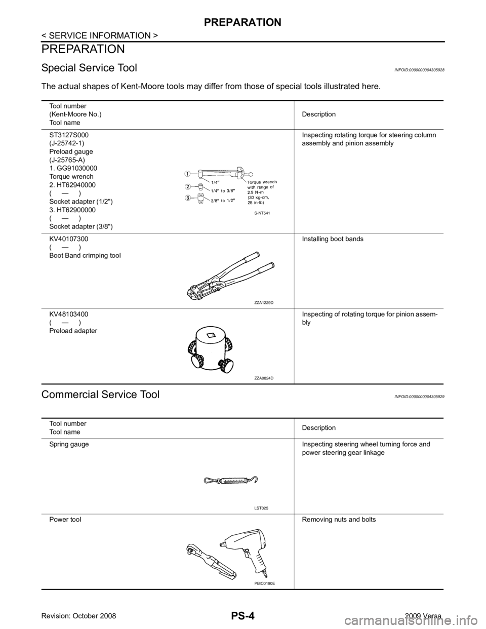
Special Service Tool INFOID:0000000004305928
The actual shapes of K ent-Moore tools may differ from thos e of special tools illustrated here.
Commercial Service Tool INFOID:0000000004305929
Tool number
(Kent-Moore No.)
Tool name Description
ST3127S000
(J-25742-1)
Preload gauge
(J-25765-A)
1. GG91030000
Torque wrench
2. HT62940000
( — )
Socket adapter (1/2")
3. HT62900000
( — )
Socket adapter (3/8") Inspecting rotating torque for steering column
assembly and pinion assembly
KV40107300
( — )
Boot Band crimping tool Installing boot bands
KV48103400
( — )
Preload adapter Inspecting of rotating torque for pinion assem-
bly S-NT541
ZZA1229D
ZZA0824D
Tool number
Tool name Description
Spring gauge Inspecting steering wheel turning force and
power steering gear linkage
Power tool Removing nuts and bolts LST025
PBIC0190E
Page 4082 of 4331

RF
N
O P
CONTENTS
ROOF
PRECAUTION ....... ........................................2
PRECAUTIONS .............................................. .....2
Precaution for Supplemental Restraint System
(SRS) "AIR BAG" and "SEAT BELT PRE-TEN-
SIONER" ............................................................. ......
2
Precaution Necessary fo r Steering Wheel Rota-
tion After Battery Disconnect ............................... ......
2
Precaution ........................................................... ......2
PREPARATION .... ........................................4
PREPARATION .............................................. .....4
Commercial Service Tool .................................... ......4
SYMPTOM DIAGNOSIS ..... ..........................5
SQUEAK AND RATTLE TROUBLE DIAG-
NOSES ........................ ........................................5
Work Flow ........................................................... ......5
Generic Squeak and Rattle Troubleshooting ...... ......7
Diagnostic Worksheet ......................................... ......9
FUNCTION DIAGNOSIS .. ............................11
TROUBLE DIAGNOSIS ................................. ....11 Component Parts and Harness Connector Loca-
tion ....................................................................... ....
11
System Description .............................................. ....11
CAN Communication System Description ........... ....13
Wiring Diagram - SROOF - .................................. ....14
Terminal and Reference Value for BCM ..................15
Terminal and Reference Value for Sunroof Motor
Assembly ............................................................. ....
16
Work Flow ............................................................ ....16
CONSULT-III Function (B CM) .................................16
Work Support ....................................................... ....17
Active Test ........................................................... ....17
Data Monitor ........................................................ ....17
Trouble Diagnosis Chart by Symptom ................. ....17
BCM Power Supply and Ground Circuit Inspection ....17
Sunroof Switch System Inspection ...................... ....17
Sunroof Motor Assembly Power Supply and
Ground Circuit Inspection .................................... ....
19
Door Switch Check .............................................. ....20
ON-VEHICLE REPAIR ..... ............................22
SUNROOF ......................................................... 22
Removal and Installation ..................................... ....22
Fitting Adjustment ................................................ ....27
Inspection ............................................................ ....28
Page 4193 of 4331

SRS
N
O P
OPERATION PROCEDURE
1. Connect both battery cables. NOTE:
Supply power using jumper cables if battery is discharged.
2. Use the Intelligent Key or mechanical key to turn the ignition switch to the ″ACC ″ position. At this time, the
steering lock will be released.
3. Disconnect both battery cables. The steering lock will remain released and the steering wheel can be
rotated.
4. Perform the necessary repair operation.
5. When the repair work is completed, return the ignition switch to the ″LOCK ″ position before connecting
the battery cables. (At this time, the steering lock mechanism will engage.)
6. Perform a self-diagnosis check of al l control units using CONSULT-III.
Occupant Classification System Precaution INFOID:0000000004307174
Replace control unit and passenger front seat cushion as an assembly.
Page 4251 of 4331
STC
N
O P
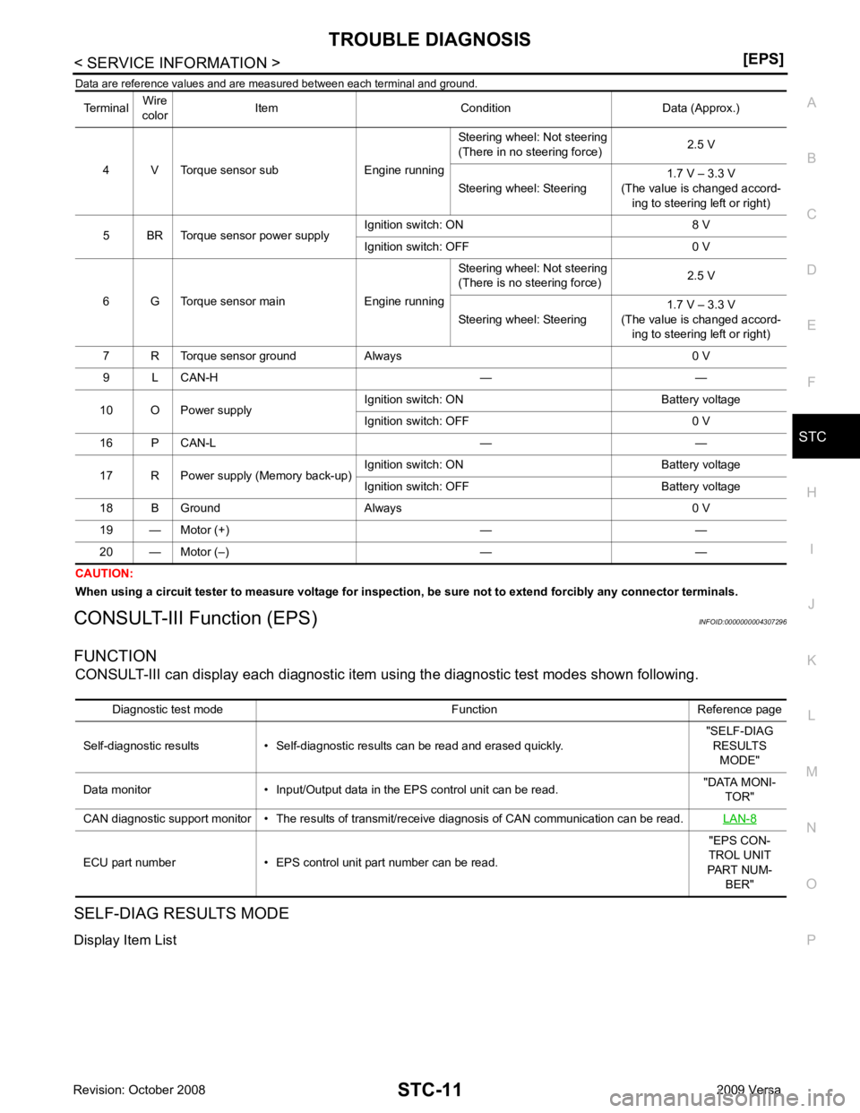
Data are reference values and are
measured between each terminal and ground.
CAUTION:
When using a circuit tester to measure voltage for inspection , be sure not to extend forcibly any connector terminals.
CONSULT-III Function (EPS) INFOID:0000000004307296
FUNCTION CONSULT-III can display each diagnostic item using the diagnostic test modes shown following.
SELF-DIAG RESULTS MODE
Display Item List Terminal
Wire
color Item Condition Data (Approx.)
4 V Torque sensor sub Engine running Steering wheel: Not steering
(There in no steering force) 2.5 V
Steering wheel: Steering 1.7 V – 3.3 V
(The value is changed accord- ing to steering left or right)
5 BR Torque sensor power supply Ignition switch: ON 8 V
Ignition switch: OFF 0 V
6 G Torque sensor main Engine running Steering wheel: Not steering
(There is no steering force) 2.5 V
Steering wheel: Steering 1.7 V – 3.3 V
(The value is changed accord- ing to steering left or right)
7 R Torque sensor ground Always 0 V
9 L CAN-H — —
10 O Power supply Ignition switch: ON Battery voltage
Ignition switch: OFF 0 V
16 P CAN-L — —
17 R Power supply (Memory back-up) Ignition switch: ON Battery voltage
Ignition switch: OFF Battery voltage
18 B Ground Always 0 V
19 — Motor (+) — —
20 — Motor (–) — — Diagnostic test mode Function Reference page
Self-diagnostic results • Self-diagnostic results can be read and erased quickly. "SELF-DIAG
RESULTS MODE"
Data monitor • Inpu t/Output data in the EPS control unit can be read. "DATA MONI-
TOR"
CAN diagnostic support monitor • The results of transmit/receive diagnosis of CAN communication can be read. LAN-8ECU part number • EPS control unit
part number can be read. "EPS CON-
TROL UNIT
PART NUM- BER"
Page 4252 of 4331
![NISSAN LATIO 2009 Service Manual PDF DTC C1601
BATTERY VOLT "
TORQUE SENSOR
[C1604] When the torque sensor malfunction assembled in steering column
assembly is detected. STC-15, " DTC C1604
TORQUE SENSOR "
EPS MOTOR
[C1606] When the](/img/5/57359/w960_57359-4251.png "NISSAN LATIO 2009 Service Manual PDF DTC C1601
BATTERY VOLT \"
TORQUE SENSOR
[C1604] When the torque sensor malfunction assembled in steering column
assembly is detected. STC-15, \" DTC C1604
TORQUE SENSOR \"
EPS MOTOR
[C1606] When the")
DTC C1601
BATTERY VOLT "
TORQUE SENSOR
[C1604] When the torque sensor malfunction assembled in steering column
assembly is detected. STC-15, " DTC C1604
TORQUE SENSOR "
EPS MOTOR
[C1606] When the motor driver
malfunction of EPS control unit or EPS motor
malfunction is detected. STC-16, " DTC C1606
EPS MOTOR "
EEPROM
[C1607] When the memory (EEPROM) system malfunction is detected in
EPS control unit. STC-17, " DTC C1607
EEPROM "
CONTROL UNIT
[C1608] When the internal malfunction is detected in EPS control unit. STC-17, " DTC C1608
CONTROL UNIT "
CAN VHCL SPEED
[C1609] When the malfunction is detected in vehicle speed signal received
with CAN communication. STC-18, " DTC C1609
CAN VHCL SPEED "
CAN ENG RPM
[C1610] When the malfunction is detected in engine status signal received
with CAN communication. STC-19, " DTC C1610
CAN ENG RPM "
CAN COMM CIRCUIT
[U1000] When EPS control unit is
not transmitting or receiving CAN commu-
nication signal 2 seconds or more. STC-19, " DTC U1000
CAN COMM CIRCUIT "
NO DTC IS DETECTED.
FURTHER TESTING MAY BE RE-
QUIRED. No NG item has been detected. —Monitor item (Unit) Remarks
MOTOR VOL (V) Power supply voltage for EPS control unit is displayed
TORQUE SENSOR (Nm) Steering wheel turning force detected by torque sensor is displayed
MOTOR SIG (A) Current commanded value to EPS motor is displayed
MOTOR CURRENT (A) Current value cons umed by EPS motor is displayed
VEHICLE SPEED (km/h) or (mph) Vehicle speed is displayed from vehicle speed signal with CAN communication
WARNING LAMP (ON/OFF) EPS warning la mp control status is displayed
DERATING STAT (ON/OFF) Protect overload status is displayed
ENGINE STATUS (STOP/RUN) Engine spee d is displayed from engine status signal with CAN communication
Page 4253 of 4331
STC
N
O P
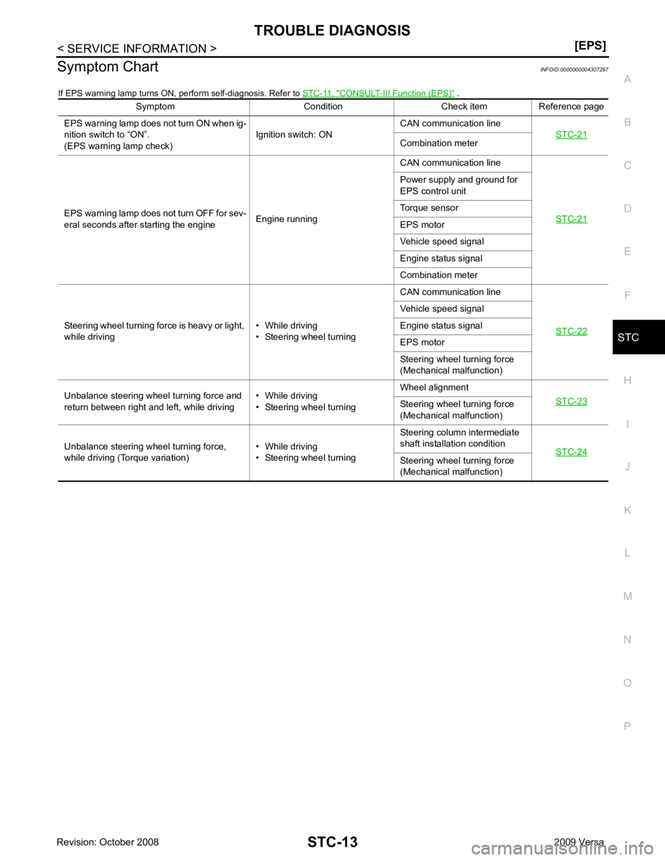
Symptom Chart
INFOID:0000000004307297
If EPS warning lamp turns ON, perform self-diagnosis. Refer to STC-11, " CONSULT-III Function (EPS) " .
Symptom Condition Check item Reference page
EPS warning lamp does not turn ON when ig-
nition switch to “ON”.
(EPS warning lamp check) Ignition switch: ONCAN communication line
STC-21 Combination meter
EPS warning lamp does not turn OFF for sev-
eral seconds after starting the engine Engine runningCAN communication line
STC-21 Power supply and ground for
EPS control unit
Torque sensor
EPS motor
Vehicle speed signal
Engine status signal
Combination meter
Steering wheel turning force is heavy or light,
while driving • While driving
• Steering wheel turning CAN communication line
STC-22 Vehicle speed signal
Engine status signal
EPS motor
Steering wheel turning force
(Mechanical malfunction)
Unbalance steering wheel turning force and
return between right and left, while driving • While driving
• Steering wheel turning Wheel alignment
STC-23 Steering wheel
turning force
(Mechanical malfunction)
Unbalance steering wheel turning force,
while driving (Torque variation) • While driving
• Steering wheel turning Steering column intermediate
shaft installation condition STC-24 Steering wheel
turning force
(Mechanical malfunction)
Page 4255 of 4331
STC
N
O P
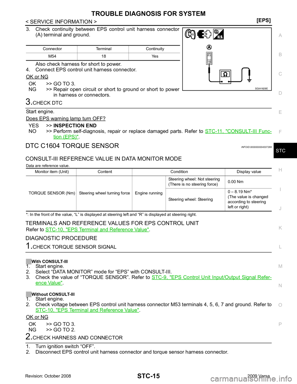
3. Check continuity between EPS control unit harness connector
(A) terminal and ground.
Also check harness for short to power.
4. Connect EPS control unit harness connector.
OK or NG OK >> GO TO 3.
NG >> Repair open circuit or short to ground or short to power
in harness or connectors. YES >>
INSPECTION END
NO >> Perform self-diagnosis, repair or replace damaged parts. Refer to STC-11, " CONSULT-III Func-
tion (EPS) " .
DTC C1604 TORQUE SENSOR INFOID:0000000004307299
CONSULT-III REFERENCE VALUE IN DATA MONITOR MODE Data are reference value.
*: In the front of the value, “L” is displayed at steering left and “R” is displayed at steering right.
TERMINALS AND REFERENCE VA LUES FOR EPS CONTROL UNIT
Refer to STC-10, " EPS Terminal and Reference Value " .
DIAGNOSTIC PROCEDURE EPS Control Unit Input/Output Signal Refer-
ence Value " .
Without CONSULT-III
1. Start engine.
2. Check voltage between EPS control unit harness connec tor M53 terminals 4, 5, 6, 7 and ground. Refer to
STC-10, " EPS Terminal and Reference Value " .
OK or NG OK >> GO TO 3.
NG >> GO TO 2.
Page 4262 of 4331
![NISSAN LATIO 2009 Service Manual PDF STC-22< SERVICE INFORMATION >
[EPS]
TROUBLE DIAGNOSIS FOR SYMPTOMS
5. Turn ignition switch “OFF”.
6. Check voltage between EPS control unit harness connector (A) terminals and ground.
7. Connect E](/img/5/57359/w960_57359-4261.png "NISSAN LATIO 2009 Service Manual PDF STC-22< SERVICE INFORMATION >
[EPS]
TROUBLE DIAGNOSIS FOR SYMPTOMS
5. Turn ignition switch “OFF”.
6. Check voltage between EPS control unit harness connector (A) terminals and ground.
7. Connect E")
STC-22< SERVICE INFORMATION >
[EPS]
TROUBLE DIAGNOSIS FOR SYMPTOMS
5. Turn ignition switch “OFF”.
6. Check voltage between EPS control unit harness connector (A) terminals and ground.
7. Connect EPS control unit harness connector.
OK or NG OK >> GO TO 3.
NG >> Check the following. If any items are damaged, repair or replace damaged parts.
• 60 A fusible link (No. m, located in the fuse and fusible link block). Refer to PG-3 .
• 10 A fuse [No. 2, located in the fuse block (J/B)]. Refer to PG-3 .
• Harness for short or open between battery and EPS control unit harness connector M54 termi-
nal 17.
• Harness for short or open between ignition switch and EPS control unit harness connector M53 terminal 10. 3.
CHECK EPS CONTROL UNIT GROUND CIRCUIT
1. Turn ignition switch “OFF”.
2. Disconnect EPS control unit harness connector.
3. Check continuity between EP S control unit harness connector
(A) terminal and ground.
Also check harness for short to power.
4. Connect EPS control unit harness connector.
OK or NG OK >> GO TO 4.
NG >> Repair open circuit or short to ground or short to power in harness or connectors. 4.
CHECK EPS CONTROL UNIT
Check EPS control unit input/output signal. Refer to STC-9, " EPS Control Unit Input/Output Signal Reference
Value " .
OK or NG OK >> GO TO 5.
NG >> Check EPS control unit pin terminals for dam age or loose connection with harness connector. If
any items are damaged, repair or replace damaged parts. 5.
SYMPTOM CHECK
Check again.
OK or NG OK >>
INSPECTION END
NG >> Replace combination meter. Refer to DI-19, " Removal and Installation " .
Steering Wheel Turning Fo rce Is Heavy or Light INFOID:0000000004307309
SYMPTOM:
Steering wheel turning force is heavy or light, while driving.
DIAGNOSTIC PROCEDURE 1.
CHECK SYSTEM FOR CAN COMMUNICATION LINE
Perform self-diagnosis. Refer to STC-11, " CONSULT-III F
unction (EPS) " .
Connector Terminal Voltage
M53 10 – Ground Approx. 0 V
M54 17 – Ground Battery voltage SGIA1627E
Connector Terminal Continuity
M54 18 YES SGIA1628E