seat adjustment NISSAN LATIO 2011 Service User Guide
[x] Cancel search | Manufacturer: NISSAN, Model Year: 2011, Model line: LATIO, Model: NISSAN LATIO 2011Pages: 3787, PDF Size: 78.35 MB
Page 2403 of 3787
![NISSAN LATIO 2011 Service User Guide DRIVE BELTSEM-13
< ON-VEHICLE MAINTENANCE > [HR16DE]
C
D
E
F
G H
I
J
K L
M A
EM
NP
O
ON-VEHICLE MAINTENANCE
DRIVE BELTS
CheckingINFOID:0000000005930924
• Inspection should be done only when engine i NISSAN LATIO 2011 Service User Guide DRIVE BELTSEM-13
< ON-VEHICLE MAINTENANCE > [HR16DE]
C
D
E
F
G H
I
J
K L
M A
EM
NP
O
ON-VEHICLE MAINTENANCE
DRIVE BELTS
CheckingINFOID:0000000005930924
• Inspection should be done only when engine i](/img/5/57357/w960_57357-2402.png)
DRIVE BELTSEM-13
< ON-VEHICLE MAINTENANCE > [HR16DE]
C
D
E
F
G H
I
J
K L
M A
EM
NP
O
ON-VEHICLE MAINTENANCE
DRIVE BELTS
CheckingINFOID:0000000005930924
• Inspection should be done only when engine is cold or over 30
minutes after the engine is stopped.
• Visually check belts for wear, damage, and cracks on inside and edges.
• Turn crankshaft pulley two times clockwise, and make sure tension on all pulleys is equal before doing the test.
• When measuring deflection, apply 98 N (10 kg, 22 lb) at the ( ) marked point.
• Measure the belt tension and frequency with acous tic tension gauge at the ( ) marked point.
CAUTION:
• When the tension and frequency are measured, the acoustic tension gauge should be used.
• When checking immediately after installation, first ad just it to the specified value. Then, after turning
crankshaft two turns or more, re-adjust to the sp ecified value to avoid variation in deflection
between pulleys.
Tension AdjustmentINFOID:0000000005930925
CAUTION:
• When belt is replaced with new one, adjust belt te nsion to the value for “New belt”, because new belt
will not fully seat in the pulley groove.
• When tension of the belt being used exceeds “Limit”, adjust it to the value for “After adjusted”.
• When installing a belt, make sure it is correctly engaged with the pulley groove.
• Never allow oil or engine coolant to get on the belt.
• Never twist or bend the belt strongly.
1. Loosen the idler pulley lock nut (A) from the tightening position with the specified torque by 45 degrees.
CAUTION:
1 : Generator
2 : Water pump
3 : Crankshaft pulley
4: A/C compressor (with A/C models)
: Idler pulley (without A/C models)
5 : Idler pulley
6: Drive belt
Belt Deflection / Belt Tension and Frequency : Refer to EM-111, "Drive Belts".
PBIC3642E
LocationLocation of adjuster and tightening method
Drive belt Adjusting bolt on idler pulley
1 : Generator
2: Water pump
3 : Crankshaft pulley
4 : A/C compressor (with A/C models)
: Idler pulley (without A/C models)
5 : Idler pulley
6: Drive belt
A : Idler pulley lock nut
B : Adjusting bolt
PBIC3643E
Revision: May 2010 2011 Versa
Page 2455 of 3787
![NISSAN LATIO 2011 Service User Guide CAMSHAFTEM-65
< ON-VEHICLE REPAIR > [HR16DE]
C
D
E
F
G H
I
J
K L
M A
EM
NP
O
10. Install timing chain. Refer to
EM-49, "Removal and Installation".
11. Install the camshaft position sensor (PHASE) to NISSAN LATIO 2011 Service User Guide CAMSHAFTEM-65
< ON-VEHICLE REPAIR > [HR16DE]
C
D
E
F
G H
I
J
K L
M A
EM
NP
O
10. Install timing chain. Refer to
EM-49, "Removal and Installation".
11. Install the camshaft position sensor (PHASE) to](/img/5/57357/w960_57357-2454.png)
CAMSHAFTEM-65
< ON-VEHICLE REPAIR > [HR16DE]
C
D
E
F
G H
I
J
K L
M A
EM
NP
O
10. Install timing chain. Refer to
EM-49, "Removal and Installation".
11. Install the camshaft position sensor (PHASE) to the rear end of cylinder head. • Tighten bolts with it seated completely.
12. Check and adjust valve clearance. Refer to EM-19, "
Inspection and Adjustment".
13. Installation of the remaining components is in the reverse order of removal.
InspectionINFOID:0000000005930956
INSPECTION AFTER REMOVAL
Oil Filter
• Make sure that there is no foreign material on the oil filter (1) and check it for clogging.
• Check the oil filter (1) for damage.
• If there is some damage, replace t he oil filter (1), the plug, and the
washer as a set.
CAUTION:
Do not reuse the washer.
Camshaft Runout
1. Put V-block on a precise flat table, and support No. 2 and 5 jour- nals of camshaft.
CAUTION:
Never support No. 1 journal (on the side of camshaft
sprocket) because it has a different diameter from the other
four locations.
2. Set a dial indicator vertically to No. 3 journal.
3. Turn camshaft to one direction with hands, and measure the camshaft runout on the dial indicator. (Total indicator reading)
4. If it exceeds the limit, replace camshaft.
Camshaft Cam Height
1. Measure the camshaft cam height with a micrometer (A).
2. If wear exceeds the limit, replace camshaft.
Camshaft Journa l Oil Clearance
CAMSHAFT JOURNAL DIAMETER
PBIC3693E
Standard and Limit:
Refer to EM-112, "
Camshaft".
PBIC2499E
Standard and Cam wear Limit:
Refer to EM-112, "
Camshaft".
PBIC3178J
Revision: May 2010 2011 Versa
Page 2572 of 3787
![NISSAN LATIO 2011 Service User Guide EM-182
< SERVICE INFORMATION >[MR18DE]
OIL SEAL
OIL SEAL
Removal and Installation
of Valve Oil SealINFOID:0000000005931021
REMOVAL
1. Remove camshafts. Refer to EM-170, "Component".
2. Remove valve NISSAN LATIO 2011 Service User Guide EM-182
< SERVICE INFORMATION >[MR18DE]
OIL SEAL
OIL SEAL
Removal and Installation
of Valve Oil SealINFOID:0000000005931021
REMOVAL
1. Remove camshafts. Refer to EM-170, "Component".
2. Remove valve](/img/5/57357/w960_57357-2571.png)
EM-182
< SERVICE INFORMATION >[MR18DE]
OIL SEAL
OIL SEAL
Removal and Installation
of Valve Oil SealINFOID:0000000005931021
REMOVAL
1. Remove camshafts. Refer to EM-170, "Component".
2. Remove valve lifters. Refer to EM-170
.
3. Rotate crankshaft, and set piston whose valve oil seal is to be removed to TDC. This will prevent valve from dropping into cylinder.
CAUTION:
When rotating crankshaft, be careful to avo id scarring front cover with timing chain.
4. Remove valve collet. • Compress valve spring using Tool, the attachment and the
adapter (A). Remove valve collet with a suitable magnet hand
(B).
CAUTION:
When working, be careful not to damage valve lifter holes.
5. Remove valve spring retainer, valve spring and valve spring seat.
6. Remove valve oil seal using Tool (A).
INSTALLATION
1. Apply new engine oil to valve oil seal joint surface and seal lip.
2. Press in valve oil seal to the height (H) shown using Tool (A).
3. Installation of the remaining components is in the reverse order of removal.
Removal and Installation of Front Oil SealINFOID:0000000005931022
REMOVAL
1. Remove the following parts.
• RH front wheel and tire. Refer to WT-7, "
Adjustment".
Tool number : KV101092S0 (J-26336-B)
PBIC3727E
Tool number :KV10107902 (J-38959)
PBIC3728E
Height (H) : 15.1 - 15.7 mm (0.594 - 0.618 in)
Tool number : KV10115600 (J-38958)
PBIC3211J
Revision: May 2010
2011 Versa
Page 2763 of 3787
SQUEAK AND RATTLE TROUBLE DIAGNOSESGW-9
< SERVICE INFORMATION >
C
DE
F
G H
J
K L
M A
B
GW
N
O P
Most of these incidents can be repaired by adjusting, se curing or insulating the item(s) or component(s) caus-
ing the noise.
SUNROOF/HEADLINING
Noises in the sunroof/headlining area can often be traced to one of the following:
1. Sunroof lid, rail, linkage or seals making a rattle or light knocking noise
2. Sun visor shaft shaking in the holder
3. Front or rear windshield touching headliner and squeaking
Again, pressing on the components to stop the noise while duplicating the conditions can isolate most of these
incidents. Repairs usually consist of insulating with felt cloth tape.
OVERHEAD CONSOLE (FRONT AND REAR)
Overhead console noises are often caused by the cons ole panel clips not being engaged correctly. Most of
these incidents are repaired by pushing up on the c onsole at the clip locations until the clips engage.
In addition look for:
1. Loose harness or harness connectors.
2. Front console map/reading lamp lense loose.
3. Loose screws at console attachment points.
SEATS
When isolating seat noise it's important to note the position the seat is in and the load placed on the seat when
the noise is present. These conditions should be duplicated when verifying and isolating the cause of the
noise.
Cause of seat noise include:
1. Headrest rods and holder
2. A squeak between the seat pad cushion and frame
3. The rear seatback lock and bracket
These noises can be isolated by moving or pressing on the suspected components while duplicating the con-
ditions under which the noise occurs. Most of thes e incidents can be repaired by repositioning the component
or applying urethane tape to the contact area.
UNDERHOOD
Some interior noise may be caused by components under the hood or on the engine wall. The noise is then
transmitted into the passenger compartment.
Causes of transmitted underhood noise include:
1. Any component mounted to the engine wall
2. Components that pass through the engine wall
3. Engine wall mounts and connectors
4. Loose radiator mounting pins
5. Hood bumpers out of adjustment
6. Hood striker out of adjustment
These noises can be difficult to isolate since they cannot be reached from the interior of the vehicle. The best
method is to secure, move or insulate one component at a time and test drive the vehicle. Also, engine RPM
or load can be changed to isolate the noise. Repairs can usually be made by moving, adjusting, securing, or
insulating the component causing the noise.
Revision: May 2010 2011 Versa
Page 2829 of 3787

IP-8
< SYMPTOM DIAGNOSIS >
SQUEAK AND RATTLE TROUBLE DIAGNOSES
2. Trunk lid striker out of adjustment
3. The trunk lid torsion bars knocking together
4. A loose license plate or bracket
Most of these incidents can be repaired by adjusting, securing or insulating the item(s) or component(s) caus-
ing the noise.
SUNROOF/HEADLINING
Noises in the sunroof/headlining area c an often be traced to one of the following:
1. Sunroof lid, rail, linkage or seals making a rattle or light knocking noise
2. Sun visor shaft shaking in the holder
3. Front or rear windshield touching headliner and squeaking
Again, pressing on the components to stop the noise while duplicating the conditions can isolate most of these
incidents. Repairs usually consist of insulating with felt cloth tape.
OVERHEAD CONSOLE (FRONT AND REAR)
Overhead console noises are often caused by the c onsole panel clips not being engaged correctly. Most of
these incidents are repaired by pushing up on the c onsole at the clip locations until the clips engage.
In addition look for:
1. Loose harness or harness connectors.
2. Front console map/reading lamp lens loose.
3. Loose screws at console attachment points.
SEATS
When isolating seat noise it's important to note the pos ition the seat is in and the load placed on the seat when
the noise is present. These conditions should be duplicated when verifying and isolating the cause of the
noise.
Cause of seat noise include:
1. Headrest rods and holder
2. A squeak between the seat pad cushion and frame
3. The rear seatback lock and bracket
These noises can be isolated by moving or pressing on the suspected components while duplicating the con-
ditions under which the noise occurs. Most of thes e incidents can be repaired by repositioning the component
or applying urethane tape to the contact area.
UNDERHOOD
Some interior noise may be caused by components under the hood or on the engine wall. The noise is then
transmitted into the passenger compartment.
Causes of transmitted underhood noise include:
1. Any component mounted to the engine wall
2. Components that pass through the engine wall
3. Engine wall mounts and connectors
4. Loose radiator mounting pins
5. Hood bumpers out of adjustment
6. Hood striker out of adjustment
These noises can be difficult to isolate since they cannot be reached from the interior of the vehicle. The best
method is to secure, move or insulate one component at a time and test drive the \
vehicle. Also, engine RPM
or load can be changed to isolate the noise. Repairs can usually be made by moving, adjusting, securing, or
insulating the component causing the noise.
Revision: May 2010 2011 Versa
Page 3033 of 3787
LT-1
ELECTRICAL
C
DE
F
G H
I
J
L
M
SECTION LT
A
B
LT
N
O P
CONTENTS
LIGHTING SYSTEM
SERVICE INFORMATION .. ..........................3
PRECAUTIONS .............................................. .....3
Precaution for Supplemental Restraint System
(SRS) "AIR BAG" and "SEAT BELT PRE-TEN-
SIONER" ............................................................. ......
3
Precaution Necessary for Steering Wheel Rota-
tion After Battery Disconnect ............................... ......
3
HEADLAMP (FOR USA) .....................................5
Component Parts and Harness Connector Loca-
tion ...................................................................... ......
5
System Description ...................................................5
CAN COMMUNICATION SYSTEM DESCRIP-
TION .................................................................... ......
6
Schematic .................................................................7
Wiring Diagram .........................................................8
Terminal and Reference Value for BCM .................11
Terminal and Reference Value for IPDM E/R .........11
How to Perform Trouble Diagnosis .........................12
Preliminary Check ...................................................12
CONSULT-III Function (BCM) .................................12
CONSULT-III Function (IPDM E/R) .........................13
Headlamp High Beam Does Not Illuminate (Both
Sides) .................................................................. ....
15
Headlamp High Beam Does Not Illuminate (One
Side) .................................................................... ....
17
High Beam Indicator Lamp Does Not Illuminate .....18
Headlamp Low Beam Does Not Illuminate (Both
Sides) .................................................................. ....
19
Headlamp Low Beam Does Not Illuminate (One
Side) .................................................................... ....
21
Headlamps Do Not Turn OFF .................................22
Aiming Adjustment ..................................................23
Bulb Replacement ...................................................24
Removal and Installation .........................................25
Disassembly and Assembly ................................ ....25
HEADLAMP (FOR CANADA) - DAYTIME
LIGHT SYSTEM - ........................................... ....
27
Component Parts and Harness Connector Loca-
tion ....................................................................... ....
27
System Description ..................................................27
CAN Communication System Description ...............29
Schematic ................................................................30
Wiring Diagram - DTRL - .........................................31
Terminal and Reference Value for BCM ..................34
Terminal and Reference Value for IPDM E/R ...... ....34
How to Perform Trouble Diagnosis ..........................35
Preliminary Check ...................................................35
CONSULT-III Function (BCM) .................................35
CONSULT-III Function (IPDM E/R) ..................... ....35
Daytime Light Control Does Not Operate Properly
(High Beam Headlamps Operate Properly) .............
35
Aiming Adjustment ...................................................37
Bulb Replacement ...................................................38
Removal and Installation .........................................39
Disassembly and Assembly .....................................39
FRONT FOG LAMP ..........................................41
Component Parts and Harness Connector Loca-
tion ...........................................................................
41
System Description ..................................................41
CAN Communication System Description ...............42
Wiring Diagram - F/FOG - .......................................43
Terminal and Reference Value for BCM ..................44
Terminal and Reference Value for IPDM E/R ...... ....44
How to Proceed with Trouble Diagnosis ..................45
Preliminary Check ............................................... ....45
CONSULT-III Function (BCM) .................................45
CONSULT-III Function (IPDM E/R) ..................... ....45
Front Fog lamps Do Not Illuminate (Both Sides) .....45
Front Fog Lamp Does Not Illuminate (One Side) ....47
Aiming Adjustment ...................................................48
Bulb Replacement ...................................................49
Removal and Installation .........................................49
TURN SIGNAL AND HAZARD WARNING
LAMPS ..............................................................
50
Component Parts and Harness Connector Loca-
tion ...........................................................................
50
Revision: May 2010 2011 Versa
Page 3172 of 3787
MA-1
MAINTENANCE
C
DE
F
G H
I
J
K
M
SECTION MA
A
B
MA
N
O P
CONTENTS
MAINTENANCE
SERVICE INFORMATION .. ..........................3
PRECAUTIONS .............................................. .....3
Precaution for Supplemental Restraint System
(SRS) "AIR BAG" and "SEAT BELT PRE-TEN-
SIONER" ............................................................. ......
3
Precaution Necessary for Steering Wheel Rota-
tion After Battery Disconnect ............................... ......
3
PREPARATION ...................................................5
Special Service Tool ........................................... ......5
Commercial Service Tool ..........................................6
GENERAL MAINTENANCE ........................... .....7
Explanation of General Maintenance .................. ......7
General Maintenance ................................................7
PERIODIC MAINTENANCE ................................9
Introduction of Periodic Maintenance .................. ......9
Schedule 1 ................................................................9
Schedule 2 ..............................................................11
RECOMMENDED FLUIDS AND LUBRI-
CANTS ................................................................
14
Fluids and Lubricants .......................................... ....14
SAE Viscosity Number ............................................15
Anti-freeze Coolant Mixture Ratio ...........................15
ENGINE MAINTENANCE (HR16DE) .................16
DRIVE BELT .......................................................... ....16
DRIVE BELT : Checking .........................................16
DRIVE BELT : Tension Adjustment ........................16
ENGINE COOLANT ............................................... ....17
ENGINE COOLANT : Inspection .............................17
ENGINE COOLANT : Changing Engine Coolant ....17
FUEL LINES .......................................................... ....19
FUEL LINES : Checking Fuel Line ..........................19
AIR CLEANER FILTER ......................................... ....19
AIR CLEANER FILTER : Removal and Installation
....
20
ENGINE OIL ........................................................... ....20
ENGINE OIL : Inspection .........................................20
ENGINE OIL : Draining ............................................22
ENGINE OIL : Refilling ............................................22
OIL FILTER ............................................................ ....23
OIL FILTER : Removal and Installation ...................23
SPARK PLUG (HR16DE) ...................................... ....23
SPARK PLUG (HR16DE) : Exploded View .............24
SPARK PLUG (HR16DE) : Removal and Installa-
tion ....................................................................... ....
24
EVAP VAPOR LINES ............................................ ....25
EVAP VAPOR LINES : Checking EVAP Vapor
Line ..........................................................................
25
ENGINE MAINTENANCE (MR18DE) ...............26
DRIVE BELT .......................................................... ....26
DRIVE BELT : Component ......................................26
DRIVE BELT : Checking Drive Belts .......................26
DRIVE BELT : Tension Adjustment .........................26
ENGINE COOLANT ............................................... ....26
ENGINE COOLANT : Inspection .............................26
ENGINE COOLANT : Changing Engine Coolant ....27
FUEL LINES ........................................................... ....29
FUEL LINES : Checking Fuel Line ..........................29
AIR CLEANER FILTER ......................................... ....29
AIR CLEANER FILTER : Component ......................29
AIR CLEANER FILTER : Changing Air Cleaner
Filter .........................................................................
30
ENGINE OIL ........................................................... ....30
ENGINE OIL : Inspection .........................................30
ENGINE OIL : Changing Engine Oil ........................32
OIL FILTER ............................................................ ....33
Revision: May 2010 2011 Versa
Page 3173 of 3787

MA-2
OIL FILTER : Removal and Installation ..................33
SPARK PLUG ........................................................ ...34
SPARK PLUG : Component ...................................34
SPARK PLUG : Removal and Installation ..............35
EVAP VAPOR LINES ............................................. ...36
EVAP VAPOR LINES : Checking EVAP Vapor
Line .........................................................................
36
CHASSIS AND BODY MAINTENANCE ............37
EXHAUST SYSTEM ............................................... ...37
EXHAUST SYSTEM : Checking Exhaust System
HR16DE .............................................................. ...
37
EXHAUST SYSTEM : Checking Exhaust System
MR18DE .............................................................. ...
37
CVT FLUID ............................................................. ...37
CVT FLUID : Checking CVT Fluid ..........................37
CVT FLUID : Changing CVT Fluid ..........................38
CLUTCH FLUID ..................................................... ...39
CLUTCH FLUID : Air Bleeding Procedure ..............39
M/T OIL ................................................................... ...40
M/T OIL : Draining (RS5F91R) ...............................40
M/T OIL : Refilling (RS5F91R) ................................41
M/T OIL : Inspection (RS5F91R) ............................41
M/T OIL : Changing M/T Oil (RS6F94R) .................41
M/T OIL : Checking M/T Oil (RS6FF94R) ...............42
A/T FLUID .............................................................. ...42
A/T FLUID : Checking A/T Fluid .............................42
A/T FLUID : Changing A/T Fluid .............................43
WHEELS ................................................................. ...43
WHEELS : Adjustment ............................................43
BRAKE FLUID LEVEL AND LEAKS ..................... ...45
BRAKE FLUID LEVEL AND LEAKS : On Board In-
spection ...................................................................
45
BRAKE FLUID LEVEL AND LEAKS : Drain and
Refill ........................................................................
45
BRAKE LINES AND CABLES ............................... ...46
BRAKE LINES AND CABLES : Checking Brake
Line and Cables ................................................... ...
46
DISC BRAKE .......................................................... ...46
DISC BRAKE : On Board Inspection ......................46
DRUM BRAKE ....................................................... ...46
DRUM BRAKE : Inspection .....................................46
AXLE AND SUSPENSION PARTS ........................ ...47
AXLE AND SUSPENSION PARTS : Axle and
Suspension Parts ................................................. ...
47
DRIVE SHAFT ........................................................ ...48
DRIVE SHAFT : Drive Shaft ...................................48
LOCKS, HINGES AND HOOD LATCH .................. ...48
LOCKS, HINGES AND HOOD LATCH : Lubricat-
ing Locks, Hinges and Hood Latch .........................
49
SEAT BELT, BUCKLES, RETRACTORS, AN-
CHORS AND ADJUSTERS ................................... ...
49
SEAT BELT, BUCKLES, RETRACTORS, AN-
CHORS AND ADJUSTERS : Checking Seat
Belts, Buckles, Retractors, Anchors and Adjusters
...
49
Revision: May 2010 2011 Versa
Page 3187 of 3787
MA-16
< SERVICE INFORMATION >
ENGINE MAINTENANCE (HR16DE)
ENGINE MAINTENANCE (HR16DE)
DRIVE BELT
DRIVE BELT : CheckingINFOID:0000000005931137
• Inspection should be done only when engine is cold or over 30minutes after the engine is stopped.
• Visually check belts for wear, damage, and cracks on inside and edges.
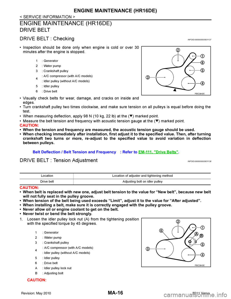
• Turn crankshaft pulley two times clockwise, and make sure tension on all pulleys is equal before doing the test.
• When measuring deflection, apply 98 N (10 kg, 22 lb) at the ( ) marked point.
• Measure the belt tension and frequency with acous tic tension gauge at the ( ) marked point.
CAUTION:
• When the tension and frequency are measured, the acoustic tension gauge should be used.
• When checking immediately after installation, first ad just it to the specified value. Then, after turning
crankshaft two turns or more, re-adjust to the specified value to avoid variation in deflection
between pulleys.
DRIVE BELT : Tension AdjustmentINFOID:0000000005931138
CAUTION:
• When belt is replaced with new one, adjust belt tension to the value for “New belt”, because new belt will not fully seat in the pulley groove.
• When tension of the belt being used exceeds “Limit”, adjust it to the value for “After adjusted”.
• When installing a belt, make sure it is correctly engaged with the pulley groove.
• Never allow oil or engine coolant to get on the belt.
• Never twist or bend the belt strongly.
1. Loosen the idler pulley lock nut (A) from the tightening position with the specified torque by 45 degrees.
CAUTION:
1 : Generator
2: Water pump
3 : Crankshaft pulley
4: A/C compressor (with A/C models)
: Idler pulley (without A/C models)
5 : Idler pulley
6: Drive belt
Belt Deflection / Belt Tension and Frequency : Refer to EM-111, "Drive Belts".
PBIC3642E
LocationLocation of adjuster and tightening method
Drive belt Adjusting bolt on idler pulley
1 : Generator
2: Water pump
3 : Crankshaft pulley
4 : A/C compressor
(with A/C models)
: Idler pulley (without A/C models)
5 : Idler pulley
6 : Drive belt
A : Idler pulley lock nut
B : Adjusting bolt
PBIC3643E
Revision: May 2010 2011 Versa
Page 3317 of 3787
MTC-1
AIR CONDITIONER
C
DE
F
G H
I
K L
M
SECTION MTC
A
B
MTC
N
O P
CONTENTS
MANUAL AIR CONDITIONER
SERVICE INFORMATION .. ..........................3
PRECAUTIONS .............................................. .....3
Precaution for Supplemental Restraint System
(SRS) "AIR BAG" and "SEAT BELT PRE-TEN-
SIONER" ............................................................. ......
3
Precaution Necessary for Steering Wheel Rota-
tion After Battery Disconnect ............................... ......
3
Precaution for Procedure without Cowl Top Cover ......4
Precaution for Working with HFC-134a (R-134a) ......4
General Refrigerant Precaution ................................4
Oil Precaution ............................................................5
Precaution for Refrigerant Connection ......................5
Precaution for Service of Compressor ................ ......8
Precaution for Service Equipment ....................... ......8
Precaution for Leak Detection Dye ...........................9
PREPARATION ..................................................11
HFC-134a (R-134a) Service Tool and Equipment ....11
Commercial Service Tool ........................................14
REFRIGERATION SYSTEM ..............................15
Refrigerant Cycle ................................................ ....15
Refrigerant System Protection ................................15
Component Part Location ................................... ....16
OIL ......................................................................17
Maintenance of Oil Quantity in Compressor ....... ....17
AIR CONDITIONER CONTROL .........................19
Control Operation ................................................ ....19
Discharge Air Flow ..................................................20
System Description .................................................20
TROUBLE DIAGNOSIS .....................................22
CONSULT-III Function (BCM) ............................. ....22
How to Perform Trouble Diagnosis for Quick and
Accurate Repair ......................................................
23
Component Parts and Harness Connector Loca-
tion ...................................................................... ....
23
Schematic ...............................................................26
Wiring Diagram - Heater - .......................................27
Wiring Diagram - A/C,M - .................................... ....28
Operational Check ...................................................31
Mode Door ...............................................................32
Air Mix Door .............................................................33
Intake Door ..............................................................34
Front Blower Motor Circuit .......................................34
Magnet Clutch Circuit (If Equipped) ..................... ....38
Insufficient Cooling ..................................................46
Insufficient Heating ..................................................53
Noise .......................................................................54
CONTROLLER ..................................................56
Removal and Installation .........................................56
Disassembly and Assembly .....................................57
THERMO CONTROL AMPLIFIER ....................58
Removal and Installation .........................................58
A/C UNIT ASSEMBLY ......................................59
Removal and Installation .........................................59
Disassembly and Assembly .....................................61
BLOWER MOTOR ............................................63
Removal and Installation .........................................63
INTAKE DOOR ..................................................64
Intake Door Cable Adjustment .................................64
AIR MIX DOOR .................................................65
Air Mix Door Cable Adjustment ...............................65
MODE DOOR ....................................................66
Mode Door Cable Adjustment .................................66
BLOWER FAN RESISTOR ...............................67
Removal and Installation .........................................67
HEATER CORE .................................................68
Removal and Installation .........................................68
DUCTS AND GRILLES .....................................69
Removal and Installation .........................................69
Revision: May 2010 2011 Versa