NISSAN LATIO 2011 Service Repair Manual
LATIO 2011
NISSAN
NISSAN
https://www.carmanualsonline.info/img/5/57357/w960_57357-0.png
NISSAN LATIO 2011 Service Repair Manual
Trending: engine coolant, brake sensor, fuel, seats, lights, start stop button, turn signal bulb
Page 2341 of 3787
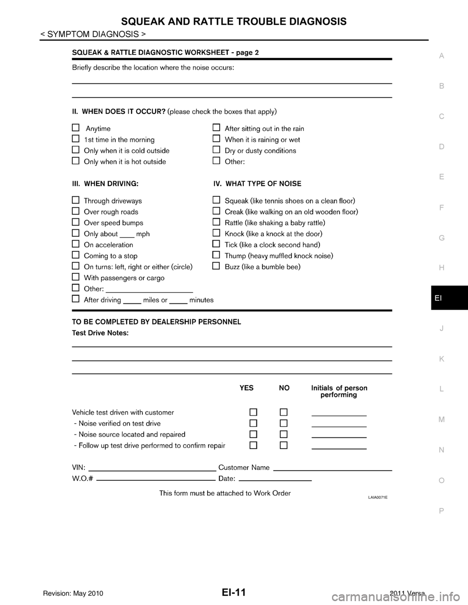
SQUEAK AND RATTLE TROUBLE DIAGNOSISEI-11
< SYMPTOM DIAGNOSIS >
C
DE
F
G H
J
K L
M A
B
EI
N
O P
LAIA0071E
Revision: May 2010 2011 Versa
Page 2342 of 3787
EI-12
< SYMPTOM DIAGNOSIS >
CLIP AND FASTENER
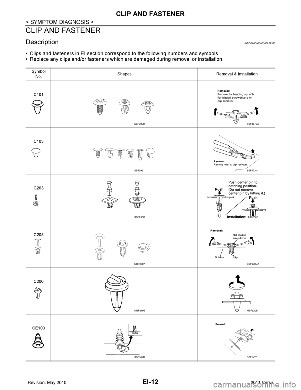
CLIP AND FASTENER
DescriptionINFOID:0000000005929553
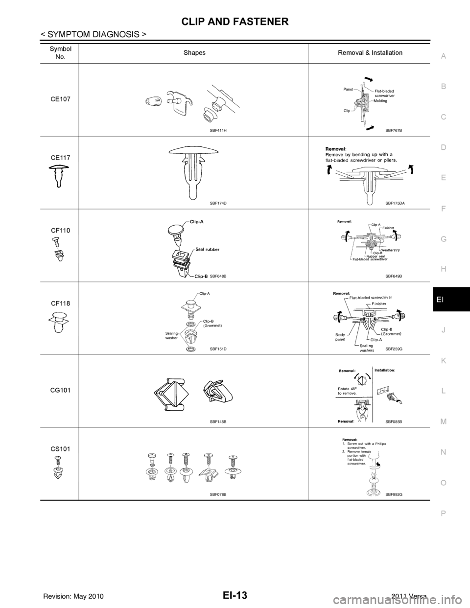
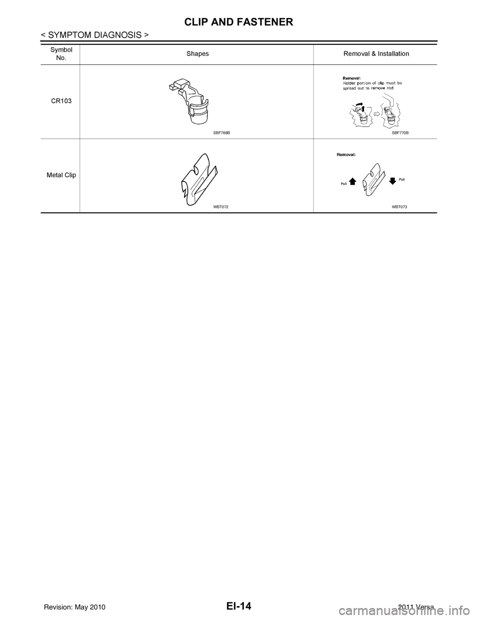
• Clips and fasteners in EI section correspond to the following numbers and symbols.
• Replace any clips and/or fasteners which are damaged during removal or installation.
Symbol No. Shapes
Removal & Installation
C101
C103
C203
C205
C206
CE103
SBF302HSBF367BA
SBT095SBF423H
SBF258GLIIA0236E
MBT080ASBF638CA
MBF519BMBF520B
SBF104BSBF147B
Revision: May 2010 2011 Versa
Page 2343 of 3787
CLIP AND FASTENEREI-13
< SYMPTOM DIAGNOSIS >
C
DE
F
G H
J
K L
M A
B
EI
N
O P
CE107
CE117
CF110
CF118
CG101 CS101
Symbol
No. Shapes
Removal & Installation
SBF411HSBF767B
SBF174DSBF175DA
SBF648BSBF649B
SBF151DSBF259G
SBF145BSBF085B
SBF078BSBF992G
Revision: May 2010 2011 Versa
Page 2344 of 3787
EI-14
< SYMPTOM DIAGNOSIS >
CLIP AND FASTENER
CR103
Metal Clip Symbol
No. Shapes
Removal & Installation
SBF768BSBF770B
WBT072WBT073
Revision: May 2010 2011 Versa
Page 2345 of 3787
FRONT BUMPEREI-15
< ON-VEHICLE REPAIR >
C
DE
F
G H
J
K L
M A
B
EI
N
O P
ON-VEHICLE REPAIR
FRONT BUMPER
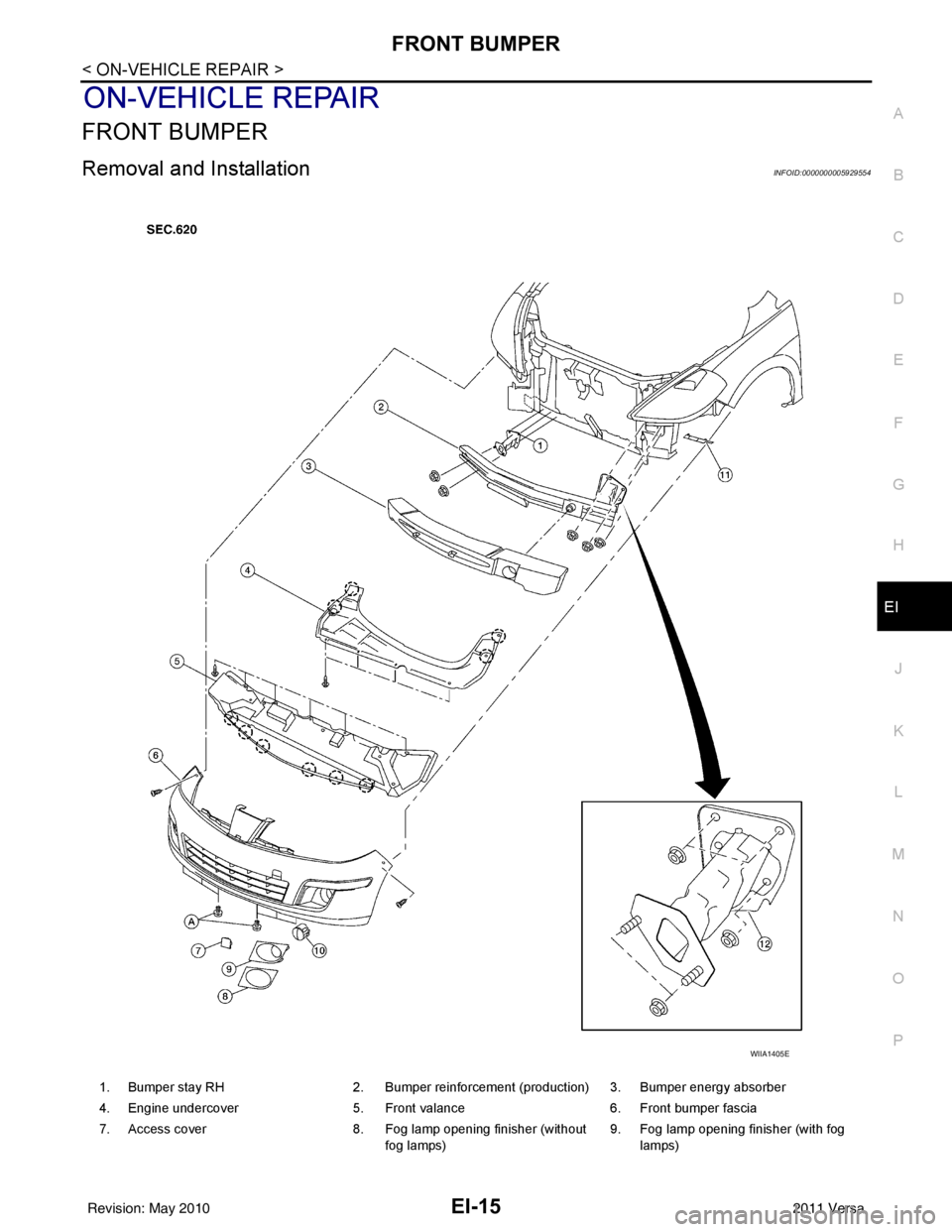
Removal and InstallationINFOID:0000000005929554
1. Bumper stay RH 2. Bumper reinforcement (production) 3. Bumper energy absorber
4. Engine undercover 5. Front valance 6. Front bumper fascia
7. Access cover 8. Fog lamp opening finisher (without
fog lamps) 9. Fog lamp opening finisher (with fog
lamps)
WIIA1405E
Revision: May 2010 2011 Versa
Page 2346 of 3787
EI-16
< ON-VEHICLE REPAIR >
FRONT BUMPER
CAUTION:
Bumper fascia is made of resin. Do not apply strong force to it, and be careful to prevent contact with
oil.
REMOVAL
1. Open hood.
2. Remove front grille. Refer to EI-23
.
3. Remove front fender protectors RH/LH. Refer to EI-26
.
4. Remove front valance and engine undercover.
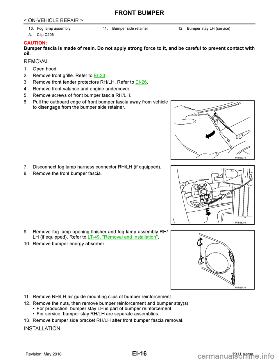
5. Remove screws of front bumper fascia RH/LH.
6. Pull the outboard edge of front bumper fascia away from vehicle to disengage from the bumper side retainer.
7. Disconnect fog lamp harness connector RH/LH (if equipped).
8. Remove the front bumper fascia.
9. Remove fog lamp opening finisher and fog lamp assembly RH/ LH (if equipped). Refer to LT-49, "
Removal and Installation".
10. Remove bumper energy absorber.
11. Remove RH/LH air guide mounting clips of bumper reinforcement.
12. Remove the nuts, then remove bumper reinforcement and bumper stay(s): • For production, bumper stay LH is part of bumper reinforcement.
• For service, bumper stay RH/LH are separate assemblies.
13. Remove bumper side bracket RH/LH after front bumper fascia removal.
INSTALLATION
10. Fog lamp assembly 11. Bumper side retainer 12. Bumper stay LH (service)
A. Clip C205
PIIB2537J
PIIB2538J
PIIB2543J
Revision: May 2010 2011 Versa
Page 2347 of 3787
FRONT BUMPEREI-17
< ON-VEHICLE REPAIR >
C
DE
F
G H
J
K L
M A
B
EI
N
O P
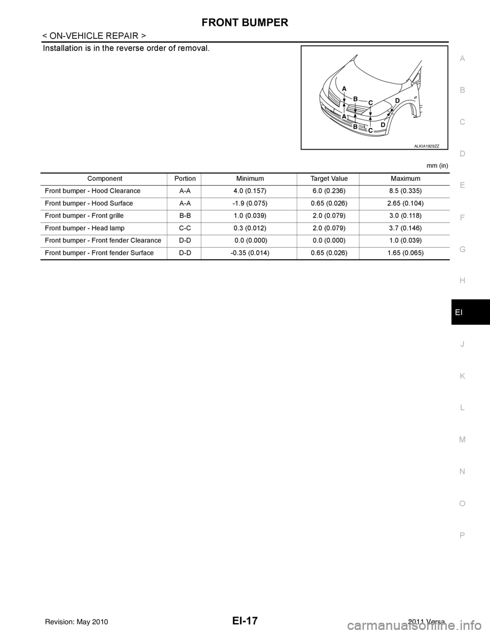
Installation is in the reverse order of removal.
mm (in)
ALKIA1929ZZ
Component PortionMinimum Target Value Maximum
Front bumper - Hood Clearance A-A 4.0 (0.157) 6.0 (0.236)8.5 (0.335)
Front bumper - Hood Surface A-A-1.9 (0.075) 0.65 (0.026)2.65 (0.104)
Front bumper - Front grille B-B1.0 (0.039) 2.0 (0.079)3.0 (0.118)
Front bumper - Head lamp C-C0.3 (0.012) 2.0 (0.079)3.7 (0.146)
Front bumper - Front fender Clearance D-D 0.0 (0.000)0.0 (0.000)1.0 (0.039)
Front bumper - Front fender Surface D-D -0.35 (0.014)0.65 (0.026)1.65 (0.065)
Revision: May 2010 2011 Versa
Page 2348 of 3787
EI-18
< ON-VEHICLE REPAIR >
REAR BUMPER
REAR BUMPER
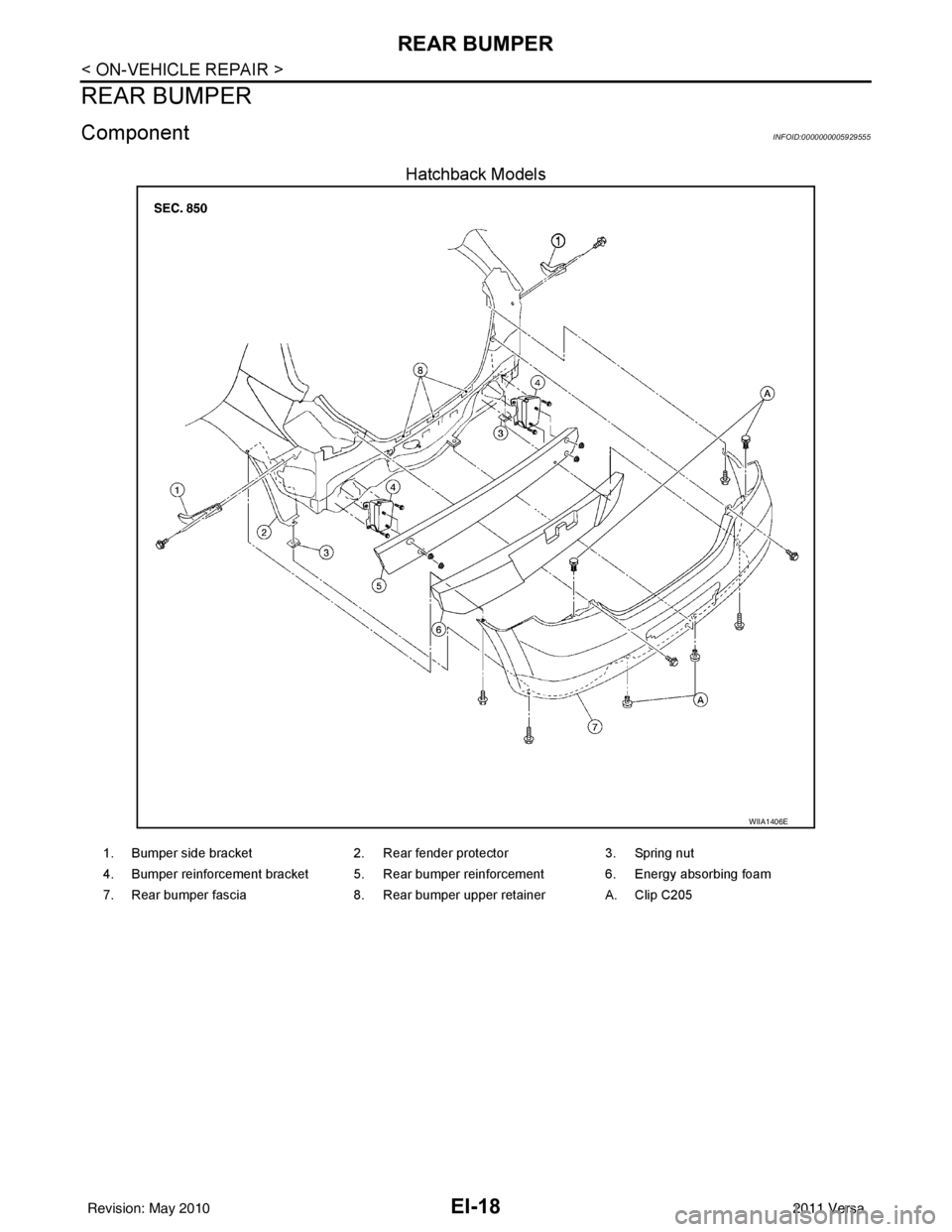
ComponentINFOID:0000000005929555
Hatchback Models
WIIA1406E
1. Bumper side bracket2. Rear fender protector 3. Spring nut
4. Bumper reinforcement bracket 5. Rear bumper reinforcement 6. Energy absorbing foam
7. Rear bumper fascia 8. Rear bumper upper retainer A. Clip C205
Revision: May 2010 2011 Versa
Page 2349 of 3787
REAR BUMPEREI-19
< ON-VEHICLE REPAIR >
C
DE
F
G H
J
K L
M A
B
EI
N
O P
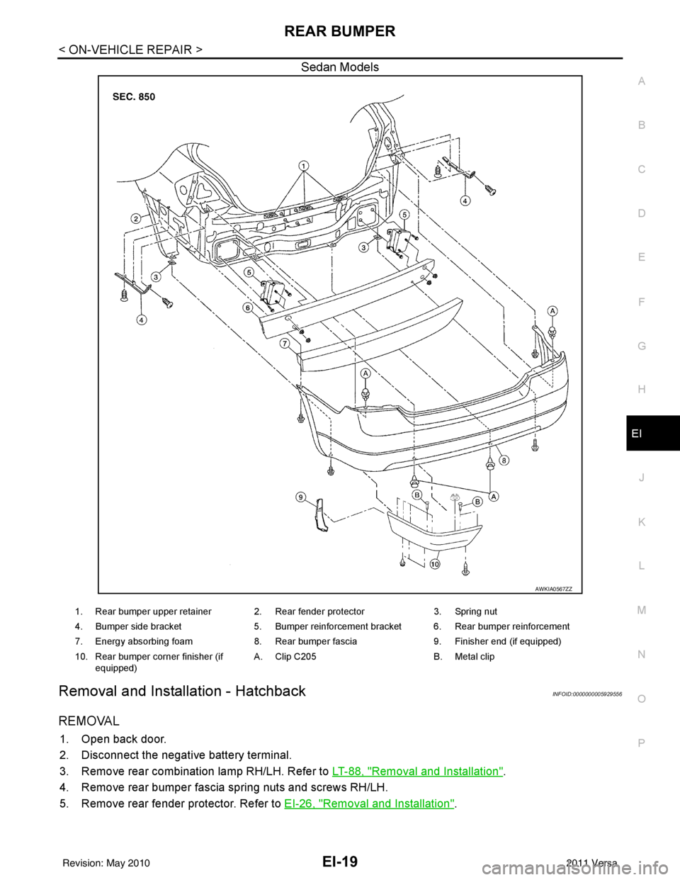
Sedan Models
Removal and Installation - HatchbackINFOID:0000000005929556
REMOVAL
1. Open back door.
2. Disconnect the negative battery terminal.
3. Remove rear combination lamp RH/LH. Refer to LT-88, "
Removal and Installation".
4. Remove rear bumper fascia spring nuts and screws RH/LH.
5. Remove rear fender protector. Refer to EI-26, "
Removal and Installation".
AWKIA0567ZZ
1. Rear bumper upper retainer 2. Rear fender protector 3. Spring nut
4. Bumper side bracket 5. Bumper reinforcement bracket 6. Rear bumper reinforcement
7. Energy absorbing foam 8. Rear bumper fascia 9. Finisher end (if equipped)
10. Rear bumper corner finisher (if equipped) A. Clip C205
B. Metal clip
Revision: May 2010 2011 Versa
Page 2350 of 3787
EI-20
< ON-VEHICLE REPAIR >
REAR BUMPER
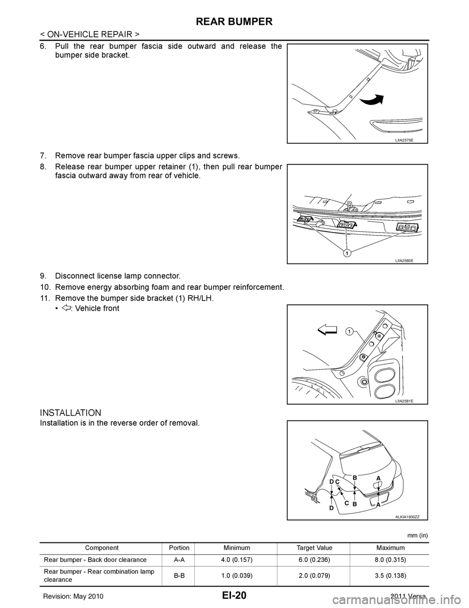
6. Pull the rear bumper fascia side outward and release thebumper side bracket.
7. Remove rear bumper fascia upper clips and screws.
8. Release rear bumper upper retainer (1), then pull rear bumper fascia outward away from rear of vehicle.
9. Disconnect license lamp connector.
10. Remove energy absorbing foam and rear bumper reinforcement.
11. Remove the bumper side bracket (1) RH/LH. • : Vehicle front
INSTALLATION
Installation is in the reverse order of removal.
mm (in)
LIIA2579E
LIIA2580E
LIIA2581E
ALKIA1930ZZ
Component PortionMinimum Target Value Maximum
Rear bumper - Back door clearance A-A 4.0 (0.157)6.0 (0.236)8.0 (0.315)
Rear bumper - Rear combination lamp
clearance B-B
1.0 (0.039) 2.0 (0.079)3.5 (0.138)
Revision: May 2010 2011 Versa
Trending: brake pads, sport mode, USB, engine oil capacity, transmission oil, battery location, oil
