NISSAN LATIO 2011 Service Repair Manual
Manufacturer: NISSAN, Model Year: 2011, Model line: LATIO, Model: NISSAN LATIO 2011Pages: 3787, PDF Size: 78.35 MB
Page 2371 of 3787
BODY SIDE TRIMEI-41
< ON-VEHICLE REPAIR >
C
DE
F
G H
J
K L
M A
B
EI
N
O P
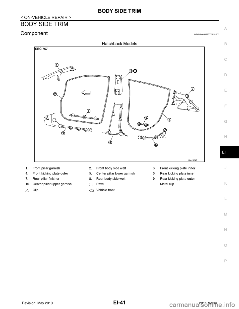
BODY SIDE TRIM
ComponentINFOID:0000000005929571
Hatchback Models
LIIA2574E
1. Front pillar garnish 2. Front body side welt 3. Front kicking plate inner
4. Front kicking plate outer 5. Center pillar lower garnish6. Rear kicking plate inner
7. Rear pillar finisher 8. Rear body side welt9. Rear kicking plate outer
10. Center pillar upper garnish PawlMetal clip
Clip Vehicle front
Revision: May 2010 2011 Versa
Page 2372 of 3787
EI-42
< ON-VEHICLE REPAIR >
BODY SIDE TRIM
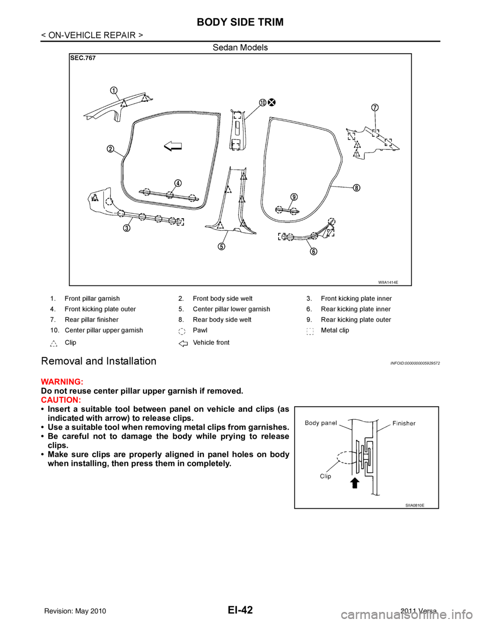
Sedan Models
Removal and InstallationINFOID:0000000005929572
WARNING:
Do not reuse center pillar upper garnish if removed.
CAUTION:
• Insert a suitable tool between panel on vehicle and clips (asindicated with arrow) to release clips.
• Use a suitable tool when removing metal clips from garnishes.
• Be careful not to damage the body while prying to release clips.
• Make sure clips are properly al igned in panel holes on body
when installing, then pr ess them in completely.
WIIA1414E
1. Front pillar garnish 2. Front body side welt3. Front kicking plate inner
4. Front kicking plate outer 5. Center pillar lower garnish6. Rear kicking plate inner
7. Rear pillar finisher 8. Rear body side welt9. Rear kicking plate outer
10. Center pillar upper garnish PawlMetal clip
Clip Vehicle front
SIIA0810E
Revision: May 2010 2011 Versa
Page 2373 of 3787
BODY SIDE TRIMEI-43
< ON-VEHICLE REPAIR >
C
DE
F
G H
J
K L
M A
B
EI
N
O P
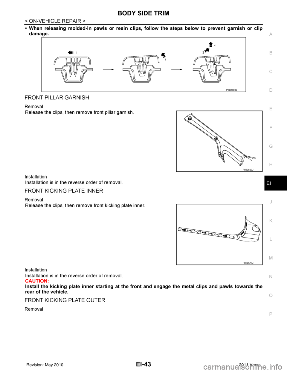
• When releasing molded-in pawls or resin clips, follow the steps below to prevent garnish or clip
damage.
FRONT PILLAR GARNISH
Removal
Release the clips, then remove front pillar garnish.
Installation
Installation is in the reverse order of removal.
FRONT KICKING PLATE INNER
Removal
Release the clips, then remove front kicking plate inner.
Installation
Installation is in the reverse order of removal.
CAUTION:
Install the kicking plate inner starting at the front and engage the metal clips and pawls towards the
rear of the vehicle.
FRONT KICKING PLATE OUTER
Removal
PIIB2600J
PIIB2569J
PIIB2570J
Revision: May 2010 2011 Versa
Page 2374 of 3787
EI-44
< ON-VEHICLE REPAIR >
BODY SIDE TRIM
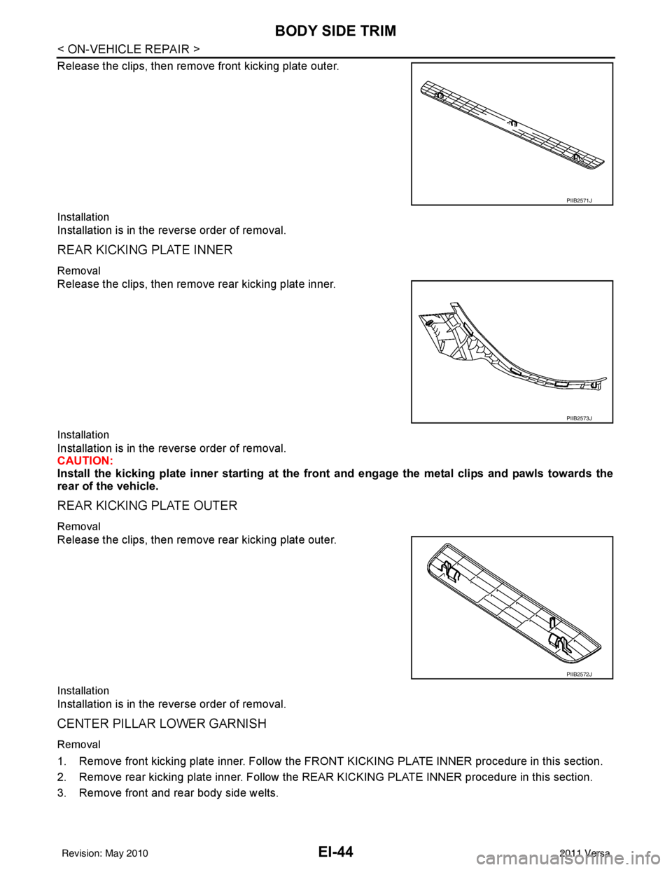
Release the clips, then remove front kicking plate outer.
Installation
Installation is in the reverse order of removal.
REAR KICKING PLATE INNER
Removal
Release the clips, then remove rear kicking plate inner.
Installation
Installation is in the reverse order of removal.
CAUTION:
Install the kicking plate inner starting at the front and engage the metal clips and pawls towards the
rear of the vehicle.
REAR KICKING PLATE OUTER
Removal
Release the clips, then remove rear kicking plate outer.
Installation
Installation is in the reverse order of removal.
CENTER PILLAR LOWER GARNISH
Removal
1. Remove front kicking plate inner. Follow the FRONT KICKING PLATE INNER procedure in this section.
2. Remove rear kicking plate inner. Follow the REAR KICKING PLATE INNER procedure in this section.
3. Remove front and rear body side welts.
PIIB2571J
PIIB2573J
PIIB2572J
Revision: May 2010 2011 Versa
Page 2375 of 3787
BODY SIDE TRIMEI-45
< ON-VEHICLE REPAIR >
C
DE
F
G H
J
K L
M A
B
EI
N
O P
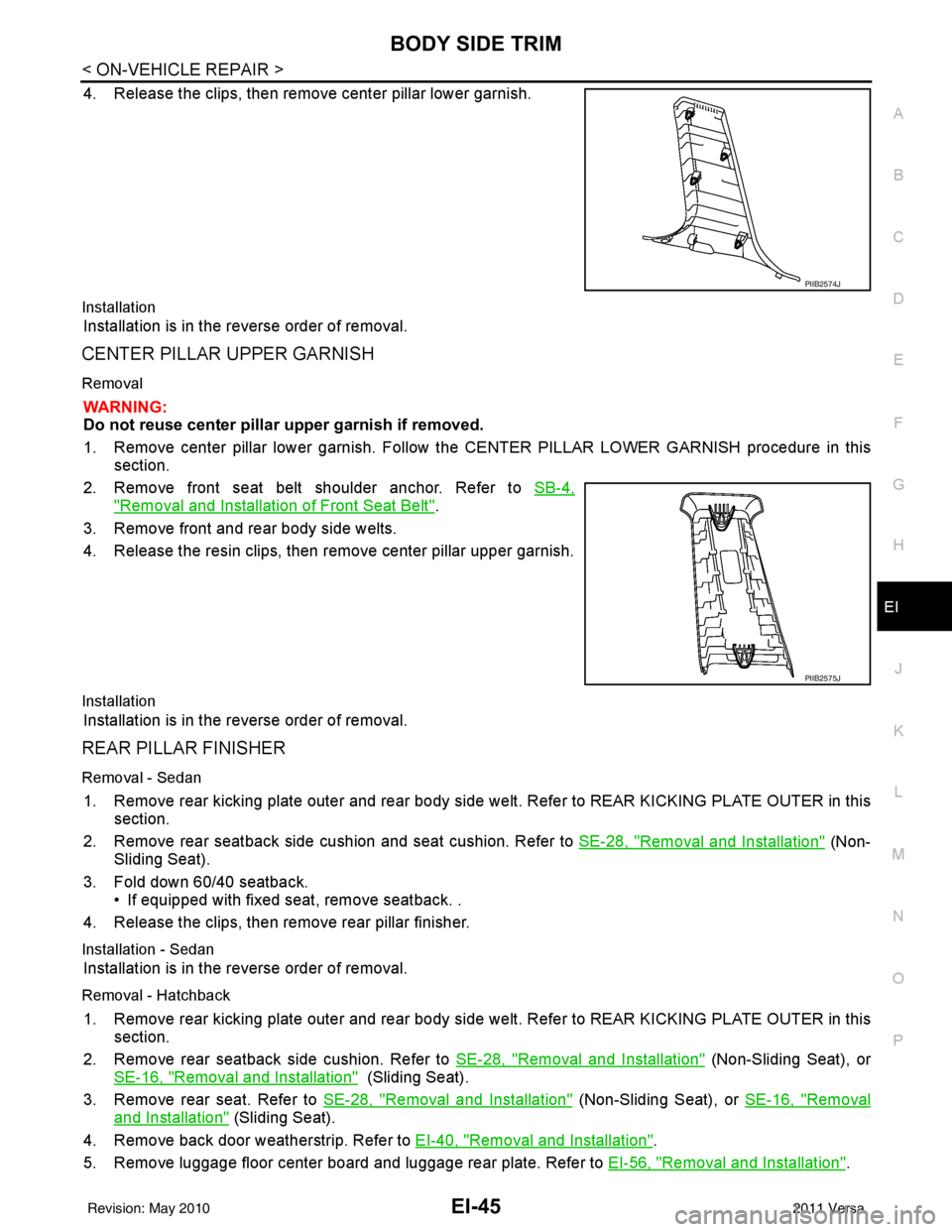
4. Release the clips, then remove center pillar lower garnish.
Installation
Installation is in the reverse order of removal.
CENTER PILLAR UPPER GARNISH
Removal
WARNING:
Do not reuse center pillar upper garnish if removed.
1. Remove center pillar lower garnish. Follow t he CENTER PILLAR LOWER GARNISH procedure in this
section.
2. Remove front seat belt shoulder anchor. Refer to SB-4,
"Removal and Installation of Front Seat Belt".
3. Remove front and rear body side welts.
4. Release the resin clips, then remove center pillar upper garnish.
Installation
Installation is in the reverse order of removal.
REAR PILLAR FINISHER
Removal - Sedan
1. Remove rear kicking plate outer and rear body side welt. Refer to REAR KICKING PLATE OUTER in this
section.
2. Remove rear seatback side cushion and seat cushion. Refer to SE-28, "
Removal and Installation" (Non-
Sliding Seat).
3. Fold down 60/40 seatback. • If equipped with fixed seat, remove seatback. .
4. Release the clips, then remove rear pillar finisher.
Installation - Sedan
Installation is in the reverse order of removal.
Removal - Hatchback
1. Remove rear kicking plate outer and rear body side welt. Refer to REAR KICKING PLATE OUTER in this
section.
2. Remove rear seatback side cushion. Refer to SE-28, "
Removal and Installation" (Non-Sliding Seat), or
SE-16, "
Removal and Installation" (Sliding Seat).
3. Remove rear seat. Refer to SE-28, "
Removal and Installation" (Non-Sliding Seat), or SE-16, "Removal
and Installation" (Sliding Seat).
4. Remove back door weatherstrip. Refer to EI-40, "
Removal and Installation".
5. Remove luggage floor center board and luggage rear plate. Refer to EI-56, "
Removal and Installation".
PIIB2574J
PIIB2575J
Revision: May 2010 2011 Versa
Page 2376 of 3787

EI-46
< ON-VEHICLE REPAIR >
BODY SIDE TRIM
6. Remove luggage side lower finisher. Refer to EI-56, "Removal and Installation".
7. Remove rear seat belt outer anchor bolt. Refer to SB-6, "
Removal and Installation of Rear Seat Belt".
8. Release the clips, then remove rear pillar finisher.
Installation - Hatchback
Installation is in the reverse order of removal.
Revision: May 2010 2011 Versa
Page 2377 of 3787
REAR PARCEL SHELF FINISHEREI-47
< ON-VEHICLE REPAIR >
C
DE
F
G H
J
K L
M A
B
EI
N
O P
REAR PARCEL SHELF FINISHER
Removal and InstallationINFOID:0000000005929573
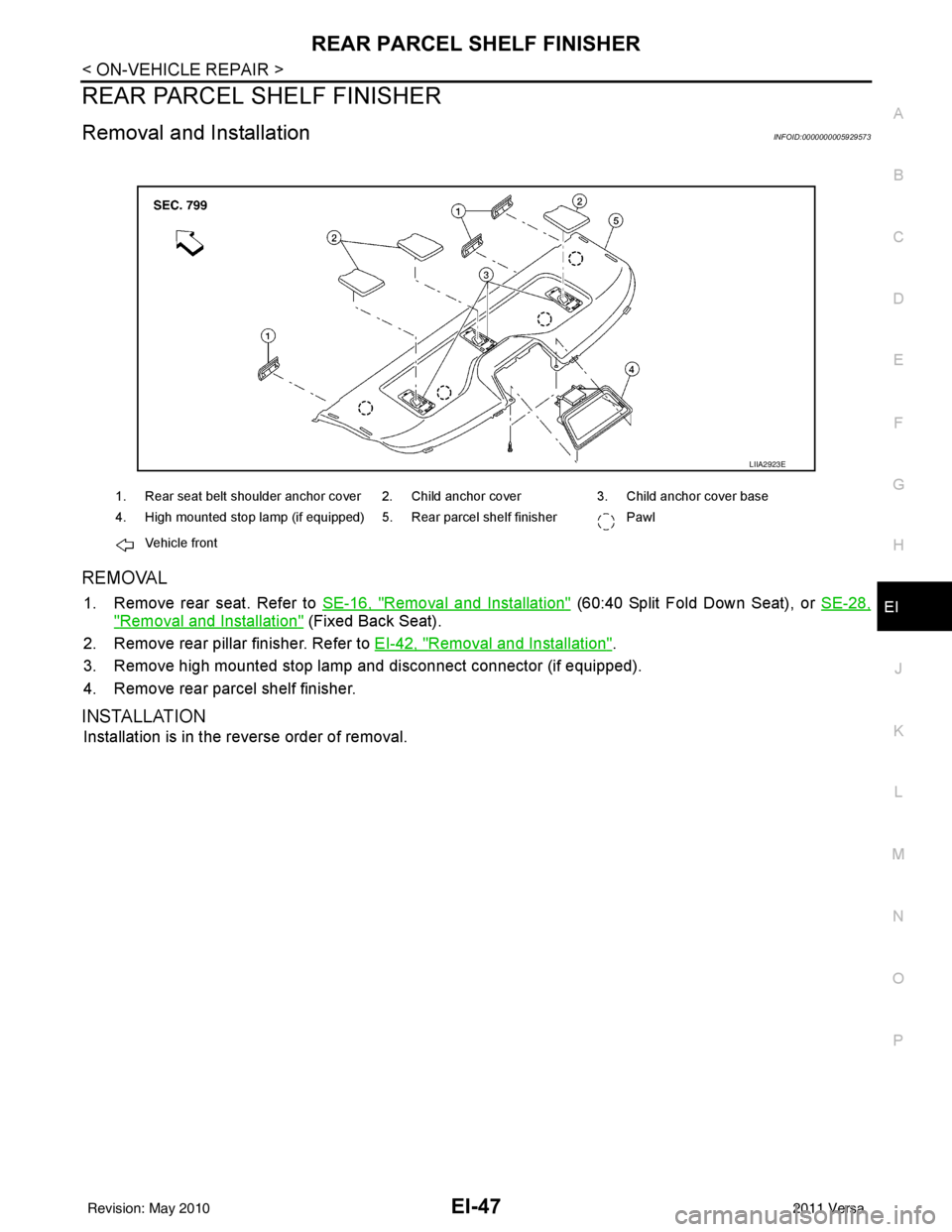
REMOVAL
1. Remove rear seat. Refer to SE-16, "Removal and Installation" (60:40 Split Fold Down Seat), or SE-28,
"Removal and Installation" (Fixed Back Seat).
2. Remove rear pillar finisher. Refer to EI-42, "
Removal and Installation".
3. Remove high mounted stop lamp and disconnect connector (if equipped).
4. Remove rear parcel shelf finisher.
INSTALLATION
Installation is in the reverse order of removal.
LIIA2923E
1. Rear seat belt shoulder anchor cover 2. Child anchor cover 3. Child anchor cover base
4. High mounted stop lamp (if equipped) 5. Rear parcel shelf finisher Pawl
Vehicle front
Revision: May 2010 2011 Versa
Page 2378 of 3787
EI-48
< ON-VEHICLE REPAIR >
FLOOR TRIM
FLOOR TRIM
Removal and InstallationINFOID:0000000005929574
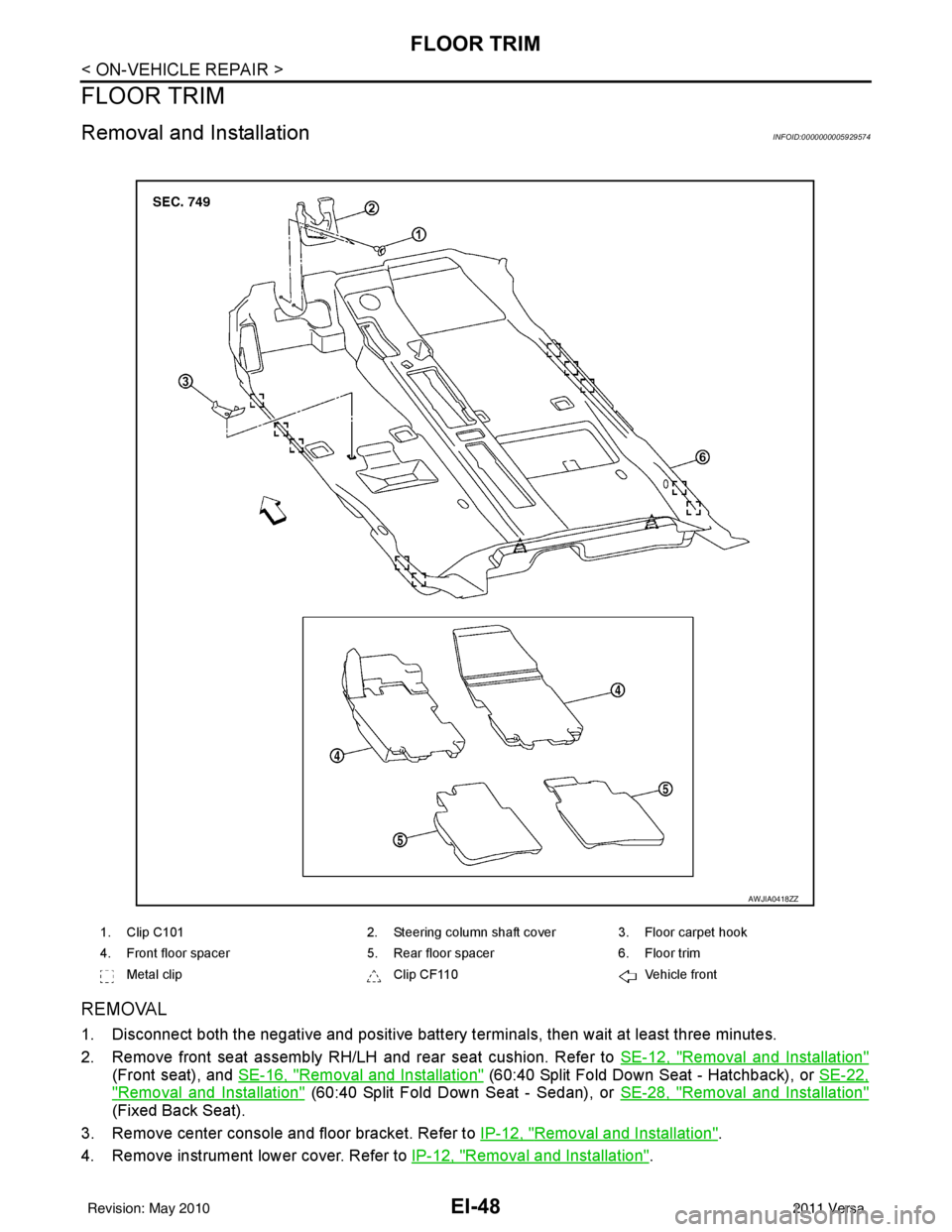
REMOVAL
1. Disconnect both the negative and positive battery terminals, then wait at least three minutes.
2. Remove front seat assembly RH/LH and rear seat cushion. Refer to SE-12, "
Removal and Installation"
(Front seat), and SE-16, "Removal and Installation" (60:40 Split Fold Down Seat - Hatchback), or SE-22,
"Removal and Installation" (60:40 Split Fold Down Seat - Sedan), or SE-28, "Removal and Installation"
(Fixed Back Seat).
3. Remove center console and floor bracket. Refer to IP-12, "
Removal and Installation".
4. Remove instrument lower cover. Refer to IP-12, "
Removal and Installation".
1. Clip C1012. Steering column shaft cover 3. Floor carpet hook
4. Front floor spacer 5. Rear floor spacer6. Floor trim
Metal clip Clip CF110Vehicle front
AWJIA0418ZZ
Revision: May 2010 2011 Versa
Page 2379 of 3787
FLOOR TRIMEI-49
< ON-VEHICLE REPAIR >
C
DE
F
G H
J
K L
M A
B
EI
N
O P
5. Remove front kicking plate inner RH/LH, center pillar lower garnish RH/LH, and rear kicking plate inner
RH/LH. Refer to EI-42, "
Removal and Installation".
6. Disconnect floor harness connector.
7. Remove diagnosis sensor unit. Refer to SRS-45
.
8. Remove key interlock cable. Refer to AT-219
.
9. Remove floor carpet hook.
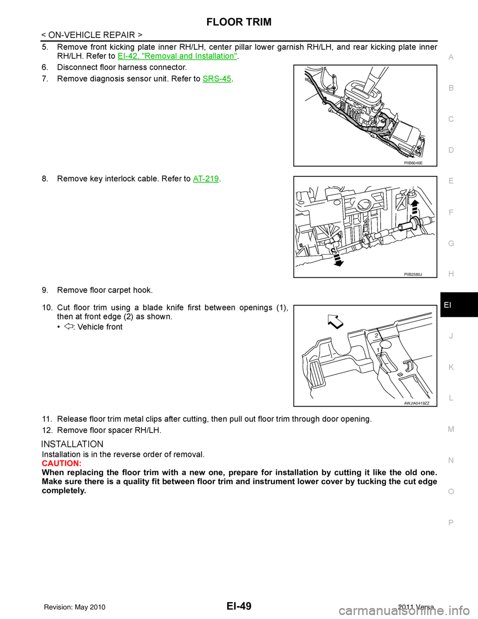
10. Cut floor trim using a blade knife first between openings (1), then at front edge (2) as shown.
• : Vehicle front
11. Release floor trim metal clips after cutting, then pull out floor trim through door opening.
12. Remove floor spacer RH/LH.
INSTALLATION
Installation is in the reverse order of removal.
CAUTION:
When replacing the floor trim with a new one, prep are for installation by cutting it like the old one.
Make sure there is a quality fit between floor trim and instrument lower cover by tucking the cut edge
completely.
PIIB6046E
PIIB2580J
AWJIA0419ZZ
Revision: May 2010 2011 Versa
Page 2380 of 3787
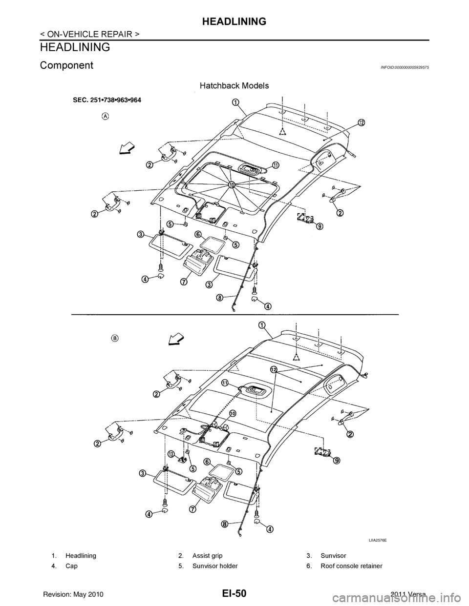
EI-50
< ON-VEHICLE REPAIR >
HEADLINING
HEADLINING
ComponentINFOID:0000000005929575
Hatchback Models
LIIA2576E
1. Headlining2. Assist grip 3. Sunvisor
4. Cap 5. Sunvisor holder 6. Roof console retainer
Revision: May 2010 2011 Versa