check transmission fluid NISSAN LATIO 2011 Service Owner's Manual
[x] Cancel search | Manufacturer: NISSAN, Model Year: 2011, Model line: LATIO, Model: NISSAN LATIO 2011Pages: 3787, PDF Size: 78.35 MB
Page 201 of 3787
AT-184
< SERVICE INFORMATION >
TROUBLE DIAGNOSIS FOR SYMPTOMS
2. Check A/T fluid condition. Refer to AT-51, "Inspections Before Trouble Diagnosis" .
OK or NG
OK >> GO TO 5.
NG >> GO TO 4.
4.DETECT MALFUNCTIONING ITEM
1. Disassemble A/T. Refer to AT-257, "
Disassembly" .
2. Check the following items:
- Forward clutch assembly. Refer to AT-307, "
Forward and Overrun Clutches" .
- Overrun clutch assembly. Refer to AT-307, "
Forward and Overrun Clutches" .
- Reverse clutch assembly. Refer to AT-297, "
Reverse Clutch" .
OK or NG
OK >> GO TO 5.
NG >> Repair or replace damaged parts.
5.CHECK SYMPTOM
Check again. Refer to AT-56, "
Check at Idle" .
OK or NG
OK >> INSPECTION END
NG >> GO TO 6.
6.CHECK TCM
1. Check TCM input/output signals. Refer to AT-75, "
TCM Terminal and Reference Value" .
2. If NG, recheck TCM pin terminals for damage or loose connection with harness connector.
OK or NG
OK >> INSPECTION END
NG >> Repair or replace damaged parts.
Large Shock "N" → "R" PositionINFOID:0000000005928251
SYMPTOM:
There is a large shock when cha nging from “N” to “R” position.
DIAGNOSTIC PROCEDURE
1.CHECK SELF-DIAGNOSTIC RESULTS
Perform self-diagnosis. Refer to AT-77, "
CONSULT-III Function (TRANSMISSION)" or AT-82, "Diagnosis Pro-
cedure without CONSULT-III" .
Is any malfunction detected by self-diagnostic results?
YES >> Check the malfunctioning system. Refer to AT-77, "CONSULT-III Function (TRANSMISSION)" or
AT-82, "
Diagnosis Procedure without CONSULT-III" .
NO >> GO TO 2.
2.CHECK LINE PRESSURE
Check line pressure at idle with selector lever in “D” position. Refer to AT-51, "
Inspections Before Trouble
Diagnosis" .
OK or NG
OK >> GO TO 4.
NG >> GO TO 3.
3.DETECT MALFUNCTIONING ITEM
1. Remove control valve assembly. Refer to AT-222, "
Control Valve Assembly and Accumulators" .
2. Check the following items:
- Valves to control line pressure (Pressure regulator valve, pressure modifier valve, pilot valve and pilot fil- ter)
- Line pressure solenoid valve
- Oil pump assembly. Refer to AT-278, "
Oil Pump" .
OK or NG
Revision: May 2010 2011 Versa
Page 205 of 3787
AT-188
< SERVICE INFORMATION >
TROUBLE DIAGNOSIS FOR SYMPTOMS
DIAGNOSTIC PROCEDURE
1.CHECK SYMPTOM
Check symptom. Refer to AT-56, "
Check at Idle" .
Is
“Vehicle Dose Not Creep Backward in “R” Position” OK?
OK >> GO TO 2.
NG >> Go to AT-185, "
Vehicle Does Not Creep Backward in "R" Position" .
2.CHECK SELF-DIAGNOSTIC RESULTS
Perform self-diagnosis. Refer to AT-77, "
CONSULT-III Function (TRANSMISSION)" or AT-82, "Diagnosis Pro-
cedure without CONSULT-III" .
Is any malfunction detected by self-diagnostic results?
YES >> Check the malfunctioning system. Refer to AT-77, "CONSULT-III Function (TRANSMISSION)" or
AT-82, "
Diagnosis Procedure without CONSULT-III" .
NO >> GO TO 3.
3.CHECK ACCELERATOR PEDAL POSITION SENSOR
Check accelerator pedal position sensor. Refer to EC-415, "
Description" (HR16DE), EC-982, "Component
Description" (MR18DE).
OK or NG
OK >> GO TO 4.
NG >> Repair or replace accelerator pedal position sensor.
4.CHECK LINE PRESSURE
Check line pressure at stall point with selector lever in “D” position. Refer to AT-51, "
Inspections Before Trou-
ble Diagnosis" .
OK or NG
OK >> GO TO 6.
NG >> GO TO 5.
5.DETECT MALFUNCTIONING ITEM
1. Remove control valve assembly. Refer to AT-222, "
Control Valve Assembly and Accumulators" .
2. Check the following items:
- Shift valve A
- Shift valve B
- Shift solenoid valve A
- Shift solenoid valve B
- Pilot valve
- Pilot filter
3. Disassemble A/T. Refer to AT-257, "
Disassembly" .
4. Check the following items:
- Forward clutch assembly. Refer to AT-307, "
Forward and Overrun Clutches" .
- Low one-way clutch. Refer to AT-257, "
Disassembly" .
- Forward one-way clutch. Refer to AT-318, "
Rear Internal Gear and Forward Clutch Hub" .
- High clutch assembly. Refer to AT-302, "
High Clutch" .
- Torque converter. Refer to AT-257, "
Disassembly" .
- Oil pump assembly. Refer to AT-278, "
Oil Pump" .
OK or NG
OK >> GO TO 8.
NG >> Repair or replace damaged parts.
6.CHECK A/T FLUID CONDITION
1. Remove oil pan. Refer to AT-237, "
Component" .
2. Check A/T fluid condition. Refer to AT-51, "
Inspections Before Trouble Diagnosis" .
OK or NG
OK >> GO TO 7.
NG >> GO TO 5.
Revision: May 2010 2011 Versa
Page 209 of 3787
AT-192
< SERVICE INFORMATION >
TROUBLE DIAGNOSIS FOR SYMPTOMS
- Shift solenoid valve B
- Pilot valve
- Pilot filter
OK or NG
OK >> GO TO 8.
NG >> Repair or replace damaged parts.
8.CHECK SYMPTOM
Check again. Refer to AT-58, "
Cruise Test - Part 1" and AT-61, "Cruise Test - Part 2" .
OK or NG
OK >> INSPECTION END
NG >> GO TO 9.
9.CHECK TCM
1. Check TCM input/output signal. Refer to AT-75, "
TCM Terminal and Reference Value" .
2. If NG, recheck TCM pin terminals for damage or loose connection with harness connector.
OK or NG
OK >> INSPECTION END
NG >> Repair or replace damaged parts.
A/T Does Not Shift: D3→ D4INFOID:0000000005928257
SYMPTOM:
•A/T does not shift from D3 to D4 at the specified speed on “Cruise Test — Part 1” and “Cruise Test
— Part 2”.
• A/T must be warm before D
3 to D4 shift will occur.
DIAGNOSTIC PROCEDURE
1.CHECK SYMPTOM
Check symptom. Refer to AT-56, "
Check at Idle" and AT-58, "Cruise Test - Part 1" .
Are
“Vehicle Does Not Creep Forward in “D”, “2” or “1” Position” and “Vehicle Cannot Be Started from D1” OK?
YES >> GO TO 2.
NO >> Go to AT-186, "
Vehicle Does Not Creep Forward in "D", "2" or "1" Position" and AT-187, "Vehicle
Cannot Be Started from D1" .
2.CHECK SELF-DIAGNOSTIC RESULTS
Perform self-diagnosis. Refer to AT-77, "
CONSULT-III Function (TRANSMISSION)" or AT-82, "Diagnosis Pro-
cedure without CONSULT-III" .
Is any malfunction detected by self-diagnostic results?
YES >> Check the malfunctioning system. Refer to AT-77, "CONSULT-III Function (TRANSMISSION)" or
AT-82, "
Diagnosis Procedure without CONSULT-III" .
NO >> GO TO 3.
3.CHECK ACCELERATOR PEDAL POSITION SENSOR
Check accelerator pedal position sensor. Refer to EC-415, "
Description" (HR16DE), EC-982, "Component
Description" (MR18DE).
OK or NG
OK >> GO TO 4.
NG >> Repair or replace accelerator pedal position sensor.
4.CHECK A/T FLUID CONDITION
1. Remove oil pan. Refer to AT-237, "
Component" .
2. Check A/T fluid condition. Refer to AT-51, "
Inspections Before Trouble Diagnosis" .
OK or NG
OK >> GO TO 6.
NG >> GO TO 5.
Revision: May 2010 2011 Versa
Page 211 of 3787
AT-194
< SERVICE INFORMATION >
TROUBLE DIAGNOSIS FOR SYMPTOMS
2.CHECK ACCELERATOR PEDAL POSITION SENSOR
Check accelerator pedal position sensor. Refer to EC-415, "
Description" (HR16DE), EC-982, "Component
Description" (MR18DE).
OK or NG
OK >> GO TO 3.
NG >> Repair or replace accelerator pedal position sensor.
3.DETECT MALFUNCTIONING ITEM
1. Remove control valve. Refer to AT-222, "
Control Valve Assembly and Accumulators" .
2. Check following items:
- Torque converter clutch control valve
- Torque converter clutch solenoid valve
- Torque converter relief valve
- Pilot valve
- Pilot filter
3. Disassemble A/T. Refer to AT-257, "
Disassembly" .
4. Check the following items:
- Torque converter. Refer to AT-257, "
Disassembly" .
OK or NG
OK >> GO TO 4.
NG >> Repair or replace damaged parts.
4.CHECK SYMPTOM
Check again. Refer to AT-58, "
Cruise Test - Part 1" .
OK or NG
OK >> INSPECTION END
NG >> GO TO 5.
5.CHECK TCM
1. Check TCM input/output signals. Refer to AT-75, "
TCM Terminal and Reference Value" .
2. If NG, recheck TCM pin terminals for damage or loose connection with harness connector.
OK or NG
OK >> INSPECTION END
NG >> Repair or replace damaged parts.
A/T Does Not Hold Lock-up ConditionINFOID:0000000005928259
SYMPTOM:
A/T does not hold lock-up condi tion for more than 30 seconds on “Cruise Test — Part 1”.
DIAGNOSTIC PROCEDURE
1.CHECK SELF-DIAGNOSTIC RESULTS
Perform self-diagnosis. Refer to AT-77, "
CONSULT-III Function (TRANSMISSION)" or AT-82, "Diagnosis Pro-
cedure without CONSULT-III" .
Is any malfunction detected by self-diagnostic results?
YES >> Check the malfunctioning system. Refer to AT-77, "CONSULT-III Function (TRANSMISSION)" or
AT-82, "
Diagnosis Procedure without CONSULT-III" .
NO >> GO TO 2.
2.CHECK A/T FLUID CONDITION
1. Remove oil pan. Refer to AT-237, "
Component" .
2. Check A/T fluid condition. Refer to AT-51, "
Inspections Before Trouble Diagnosis" .
OK or NG
OK >> GO TO 4.
NG >> GO TO 3.
Revision: May 2010 2011 Versa
Page 213 of 3787
AT-196
< SERVICE INFORMATION >
TROUBLE DIAGNOSIS FOR SYMPTOMS
OK >>INSPECTION END
NG >> GO TO 3.
3.CHECK TCM
1. Check TCM input/output signals. Refer to AT-75, "
TCM Terminal and Reference Value" .
2. If NG, recheck TCM pin terminals for damage or loose connection with harness connector.
OK or NG
OK >> INSPECTION END
NG >> Repair or replace damaged parts.
Engine Speed Does Not Return to Idle (Light Braking D4→ D3)INFOID:0000000005928261
SYMPTOM:
Engine speed does not smoothly return to idle when A/T shifts from D4 to D3 on “Cruise Test — Part
1”.
DIAGNOSTIC PROCEDURE
1.CHECK SELF-DIAGNOSTIC RESULTS
Perform self-diagnosis. Refer to AT-77, "
CONSULT-III Function (TRANSMISSION)" or AT-82, "Diagnosis Pro-
cedure without CONSULT-III" .
Is any malfunction detected by self-diagnostic results?
YES >> Check the malfunctioning system. Refer to AT-77, "CONSULT-III Function (TRANSMISSION)" or
AT-82, "
Diagnosis Procedure without CONSULT-III" .
NO >> GO TO 2.
2.CHECK ACCELERATOR PEDAL POSITION SENSOR
Check accelerator pedal position sensor. Refer to EC-415, "
Description" (HR16DE), EC-982, "Component
Description" (MR18DE).
OK or NG
OK >> GO TO 3.
NG >> Repair or replace accelerator pedal position sensor.
3.CHECK A/T FLUID CONDITION
1. Remove oil pan. Refer to AT-237, "
Component" .
2. Check A/T fluid condition. Refer to AT-51, "
Inspections Before Trouble Diagnosis" .
OK or NG
OK >> GO TO 5.
NG >> GO TO 4.
4.DETECT MALFUNCTIONING ITEM
1. Remove control valve assembly. Refer to AT-222, "
Control Valve Assembly and Accumulators" .
2. Check the following items:
- Overrun clutch control valve
- Overrun clutch reducing valve
- Overrun clutch solenoid valve
3. Disassemble A/T. Refer to AT-257, "
Disassembly" .
4. Check the following items:
- Overrun clutch assembly. Refer to AT-307, "
Forward and Overrun Clutches" .
OK or NG
OK >> GO TO 6.
NG >> Repair or replace damaged parts.
5.DETECT MALFUNCTIONING ITEM
1. Remove control valve assembly. Refer to AT-222, "
Control Valve Assembly and Accumulators" .
2. Check the following items:
- Overrun clutch control valve
- Overrun clutch reducing valve
- Overrun clutch solenoid valve
Revision: May 2010 2011 Versa
Page 217 of 3787
AT-200
< SERVICE INFORMATION >
TROUBLE DIAGNOSIS FOR SYMPTOMS
OK >> GO TO 3
NG >> Check transmission range switch. Refer to AT-175, "
Component Inspection" .
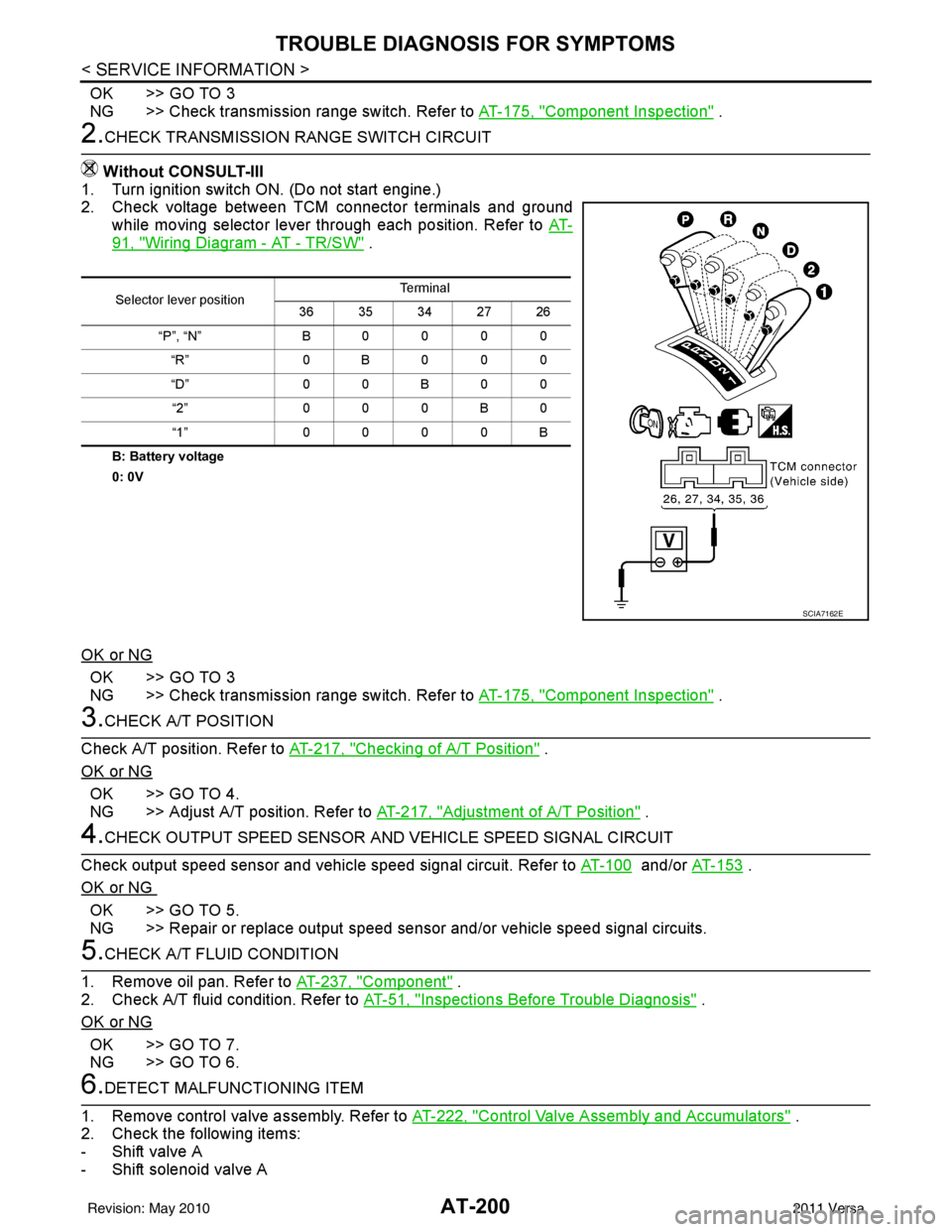
2.CHECK TRANSMISSION RANGE SWITCH CIRCUIT
Without CONSULT-III
1. Turn ignition switch ON. (Do not start engine.)
2. Check voltage between TCM connector terminals and ground
while moving selector lever through each position. Refer to AT-
91, "Wiring Diagram - AT - TR/SW" .
B: Battery voltage
0: 0V
OK or NG
OK >> GO TO 3
NG >> Check transmission range switch. Refer to AT-175, "
Component Inspection" .
3.CHECK A/T POSITION
Check A/T position. Refer to AT-217, "
Checking of A/T Position" .
OK or NG
OK >> GO TO 4.
NG >> Adjust A/T position. Refer to AT-217, "
Adjustment of A/T Position" .
4.CHECK OUTPUT SPEED SENSOR AND VEHICLE SPEED SIGNAL CIRCUIT
Check output speed sensor and vehicle speed signal circuit. Refer to AT-100
and/or AT-153 .
OK or NG
OK >> GO TO 5.
NG >> Repair or replace output speed sens or and/or vehicle speed signal circuits.
5.CHECK A/T FLUID CONDITION
1. Remove oil pan. Refer to AT-237, "
Component" .
2. Check A/T fluid condition. Refer to AT-51, "
Inspections Before Trouble Diagnosis" .
OK or NG
OK >> GO TO 7.
NG >> GO TO 6.
6.DETECT MALFUNCTIONING ITEM
1. Remove control valve assembly. Refer to AT-222, "
Control Valve Assembly and Accumulators" .
2. Check the following items:
- Shift valve A
- Shift solenoid valve A
Selector lever position Te r m i n a l
36 35 34 27 26
“P”, “N” B0000 “R” 0B000
“D” 0 0 B 0 0
“2” 000B0
“1” 0000B
SCIA7162E
Revision: May 2010 2011 Versa
Page 220 of 3787
TROUBLE DIAGNOSIS FOR SYMPTOMSAT-203
< SERVICE INFORMATION >
DE
F
G H
I
J
K L
M A
B
AT
N
O P
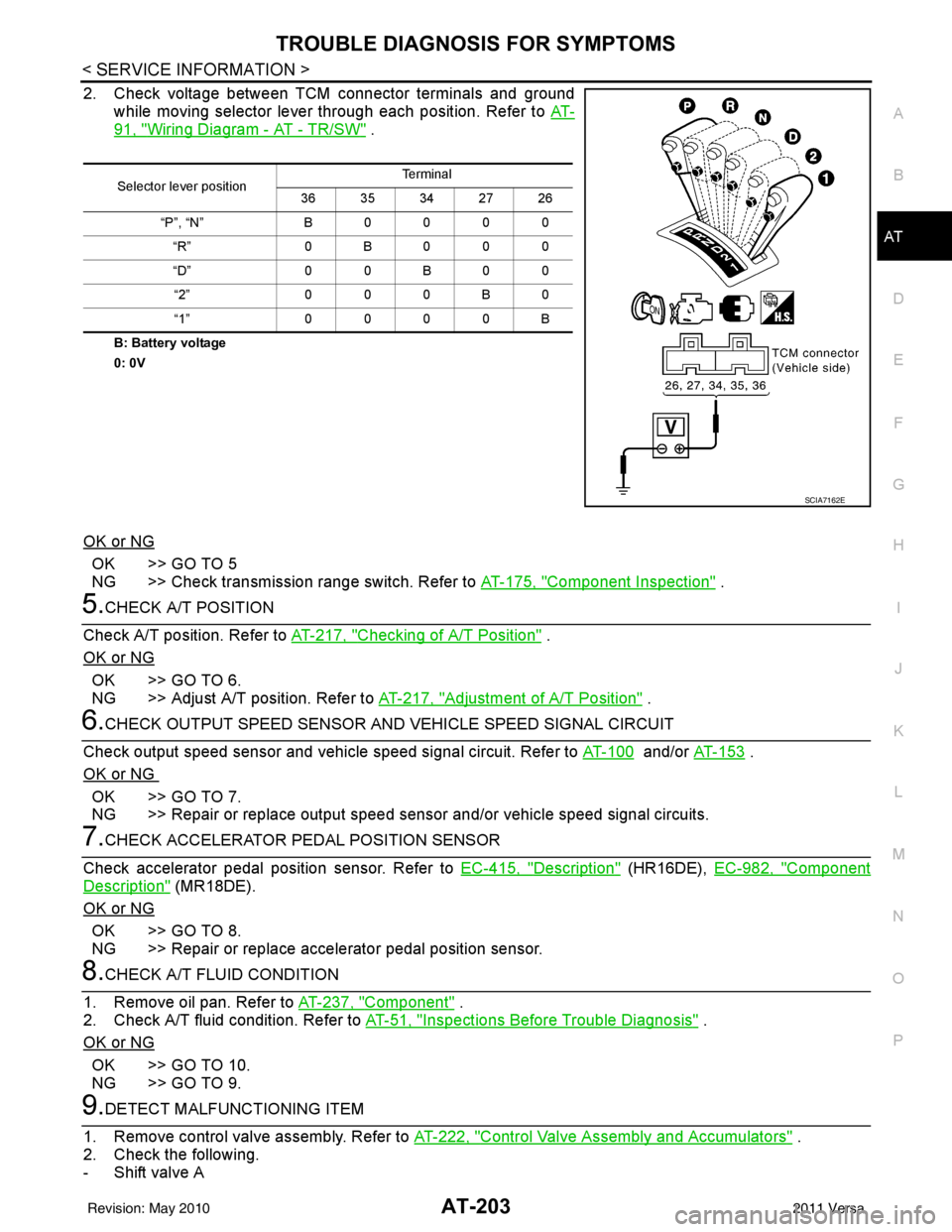
2. Check voltage between TCM connector terminals and ground while moving selector lever through each position. Refer to AT-
91, "Wiring Diagram - AT - TR/SW" .
B: Battery voltage
0: 0V
OK or NG
OK >> GO TO 5
NG >> Check transmission range switch. Refer to AT-175, "
Component Inspection" .
5.CHECK A/T POSITION
Check A/T position. Refer to AT-217, "
Checking of A/T Position" .
OK or NG
OK >> GO TO 6.
NG >> Adjust A/T position. Refer to AT-217, "
Adjustment of A/T Position" .
6.CHECK OUTPUT SPEED SENSOR AND VEHICLE SPEED SIGNAL CIRCUIT
Check output speed sensor and vehicle speed signal circuit. Refer to AT-100
and/or AT- 1 5 3 .
OK or NG
OK >> GO TO 7.
NG >> Repair or replace output speed sensor and/or vehicle speed signal circuits.
7.CHECK ACCELERATOR PEDAL POSITION SENSOR
Check accelerator pedal position sensor. Refer to EC-415, "
Description" (HR16DE), EC-982, "Component
Description" (MR18DE).
OK or NG
OK >> GO TO 8.
NG >> Repair or replace accelerator pedal position sensor.
8.CHECK A/T FLUID CONDITION
1. Remove oil pan. Refer to AT-237, "
Component" .
2. Check A/T fluid condition. Refer to AT-51, "
Inspections Before Trouble Diagnosis" .
OK or NG
OK >> GO TO 10.
NG >> GO TO 9.
9.DETECT MALFUNCTIONING ITEM
1. Remove control valve assembly. Refer to AT-222, "
Control Valve Assembly and Accumulators" .
2. Check the following.
- Shift valve A
Selector lever position Te r m i n a l
36 35 34 27 26
“P”, “N” B 0 0 0 0
“R” 0B000
“D” 0 0 B 0 0
“2” 0 0 0 B 0
“1” 0 0 0 0 B
SCIA7162E
Revision: May 2010 2011 Versa
Page 242 of 3787
ON-VEHICLE SERVICEAT-225
< SERVICE INFORMATION >
DE
F
G H
I
J
K L
M A
B
AT
N
O P
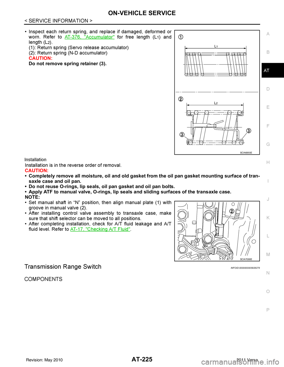
• Inspect each return spring, and replace if damaged, deformed or worn. Refer to AT-376, "
Accumulator" for free length (L1) and
length (L
2).
(1): Return spring (Servo release accumulator)
(2): Return spring (N-D accumulator)
CAUTION:
Do not remove spring retainer (3).
Installation
Installation is in the reverse order of removal.
CAUTION:
• Completely remove all moisture, oil and old gasket from the oil pan gasket mounting surface of tran-
saxle case and oil pan.
• Do not reuse O-rings, lip seals, oil pan gasket and oil pan bolts.
• Apply ATF to manual valve, O-rings, lip seals and sliding surfaces of the transaxle case.
NOTE:
• Set manual shaft in “N” position, then align manual plate (1) with groove in manual valve (2).
• After installing control valve assembly to transaxle case, make sure that shift selector can be moved to all positions.
• After completing installation, check for A/T fluid leakage and A/T fluid level. Refer to AT-17, "
Checking A/T Fluid".
Transmission Range SwitchINFOID:0000000005928279
COMPONENTS
SCIA6955E
SCIA7090E
Revision: May 2010 2011 Versa
Page 952 of 3787
![NISSAN LATIO 2011 Service Owners Manual TROUBLE DIAGNOSISBRC-63
< SERVICE INFORMATION > [VDC/TCS/ABS]
C
D
E
G H
I
J
K L
M A
B
BRC
N
O P
Note 1. If wheel sensor 2 for each wheel is indicated, check ABS actuator and electric unit (control un NISSAN LATIO 2011 Service Owners Manual TROUBLE DIAGNOSISBRC-63
< SERVICE INFORMATION > [VDC/TCS/ABS]
C
D
E
G H
I
J
K L
M A
B
BRC
N
O P
Note 1. If wheel sensor 2 for each wheel is indicated, check ABS actuator and electric unit (control un](/img/5/57357/w960_57357-951.png)
TROUBLE DIAGNOSISBRC-63
< SERVICE INFORMATION > [VDC/TCS/ABS]
C
D
E
G H
I
J
K L
M A
B
BRC
N
O P
Note 1. If wheel sensor 2 for each wheel is indicated, check ABS actuator and electric unit (control unit) power
supply voltage in addition to wheel sensor circuit check.
Note 2. If multiple malfunctions are detected including CAN communication line [U1000], perform diagnosis for
CAN communication line first.
DATA MONITOR
Display Item List
USV LINE [FL-RR]
[C1147] Front side VDC switch-over solenoid valve (cut valve) is open or
shorted, or control line is open or shorted to power supply or
ground.
BRC-72, "
Solenoid and
VDC Change-Over Valve
System Inspection"
USV LINE [FR-RL]
[C1148]Rear side VDC switch-over solenoid valve (cut valve) is open or
shorted, or control line is open or shorted to power supply or
ground.
HSV LINE [FL-RR]
[C1149] Front side VDC switch-over solenoid valve (suction valve) is open
or shorted, or control line is open or shorted to power supply or
ground.
HSV LINE [FR-RL]
[C1150] Rear side VDC switch-over solenoid valve (suction valve) is open
or shorted, or control line is open or shorted to power supply or
ground.
EMERGENCY BRAKE
[C1153] When ABS actuator and el
ectric unit (control unit) is malfunction-
ing. (Pressure increase is too much or too little) BRC-68, "
ABS/TCS/VDC
Control Unit Inspection"
PNP POS SIG
[C1154]Transmission range switch signal or communication line between
the ABS actuator and electric unit (control unit) and TCM is open
or shorted. BRC-78, "Transmission
Range Switch System In-
spection"
BR FLUID LEVEL LOW
[C1155]
Brake fluid level drops or circuit between ABS actuator and elec-
tric unit (control unit) and brake fluid level switch is open or
shorted. BRC-76, "Brake Fluid
Level Switch System In-
spection"
ST ANG SEN COM CIR
[C1156]
CAN communication line or steering angle sensor has generated
an error. BRC-79, "
CAN Commu-
nication System Inspec-
tion"
(Note 2)
VARIANT CODING
[C1170] In case where VARIANT CODING is different. BRC-68, "
ABS/TCS/VDC
Control Unit Inspection"
CAN COMM CIRCUIT
[U1000]• CAN communication line is open or shorted.
• ABS actuator and electric unit (control unit) internal malfunction
• Battery voltage for ECM is suddenly interrupted for approxi-
mately 0.5 seconds or more. BRC-79, "
CAN Commu-
nication System Inspec-
tion"
(Note 2)
Self-diagnostic item
Malfunction detecting condition Check system
Item
(Unit) Data monitor item selection
Remarks
ECU INPUT
SIGNALS MAIN
SIGNALS SELECTION
FROM MENU
FR LH SENSOR
(km/h, mph) ××× Wheel speed (km/h, mph) calculated by front LH
wheel sensor signal is displayed.
FR RH SENSOR
(km/h, mph) ××× Wheel speed (km/h, mph) calculated by front RH
wheel sensor signal is displayed.
RR LH SENSOR
(km/h, mph) ×××
Wheel speed (km/h, mph) calculated by rear LH
wheel sensor signal is displayed.
RR RH SENSOR
(km/h, mph) ××× Wheel speed (km/h, mph) calculated by rear RH
wheel sensor signal is displayed.
FR RH IN SOL
(On/Off) —
×× Front RH IN ABS solenoid (On/Off) status is dis-
played.
FR RH OUT SOL
(On/Off) —
×× Front RH OUT ABS solenoid (On/Off) status is
displayed.
FR LH IN SOL
(On/Off) —
×× Front LH IN ABS solenoid (On/Off) status is dis-
played.
Revision: May 2010
2011 Versa
Page 967 of 3787
![NISSAN LATIO 2011 Service Owners Manual BRC-78
< SERVICE INFORMATION >[VDC/TCS/ABS]
TROUBLE DIAGNOSIS FOR
SELF-DIAGNOSTIC ITEMS
1. Turn ignition switch OFF.
2. Disconnect stop lamp switch connector.
3. Check continuity between stop lamp sw NISSAN LATIO 2011 Service Owners Manual BRC-78
< SERVICE INFORMATION >[VDC/TCS/ABS]
TROUBLE DIAGNOSIS FOR
SELF-DIAGNOSTIC ITEMS
1. Turn ignition switch OFF.
2. Disconnect stop lamp switch connector.
3. Check continuity between stop lamp sw](/img/5/57357/w960_57357-966.png)
BRC-78
< SERVICE INFORMATION >[VDC/TCS/ABS]
TROUBLE DIAGNOSIS FOR
SELF-DIAGNOSTIC ITEMS
1. Turn ignition switch OFF.
2. Disconnect stop lamp switch connector.
3. Check continuity between stop lamp switch (A) (without M/T) or
(B) (with M/T) terminals 1 and 2.
Is the inspection result normal?
YES >> GO TO 4
NO >> Replace stop lamp switch.
4.CHECK STOP LAMP SWITCH CIRCUIT
1. Disconnect ABS actuator and elec tric unit (control unit) connec-
tor.
2. Connect stop lamp switch connector.
3. Check voltage between ABS actuator and electric unit (control
unit) connector E33 terminal 20 and ground.
Is the inspection result normal?
YES >> GO TO 5
NO >> Repair or replace malfunctioning components.
5.CHECK DATA MONITOR
On “DATA MONITOR”, select “PRESS SENS OR” and check the brake fluid pressure.
Is the inspection result normal?
YES >> Replace ABS actuator and electric unit (control unit). Refer to BRC-89, "Removal and Installa-
tion".
NO >> Inspection End.
Transmission Range Switch System InspectionINFOID:0000000005928495
INSPECTION PROCEDURE
1.SELF-DIAGNOSIS RESULT CHECK
Stop lamp switch terminals ConditionContinuity
1 − 2 Brake pedal depressed
Yes
Brake pedal released No
AWFIA0609ZZ
ABS actuator and elec-
tric unit (control unit) Ground Condition Vol tag e
(Approx.)
Connector Terminal
E33 20 — Brake pedal depressed Battery voltage
Brake pedal released 0V
ALFIA0016ZZ
Condition PRESS SENSOR
(DATA MONITOR)
With ignition switch turned ON and brake pedal released. Approx. 0 bar
With ignition switch turned ON and brake pedal depressed. − 40 to 300 bar
Revision: May 2010 2011 Versa