transmission NISSAN NAVARA 2005 Repair Workshop Manual
[x] Cancel search | Manufacturer: NISSAN, Model Year: 2005, Model line: NAVARA, Model: NISSAN NAVARA 2005Pages: 3171, PDF Size: 49.59 MB
Page 1678 of 3171
GI-56
IDENTIFICATION INFORMATION
IDENTIFICATION INFORMATION
PFP:00010
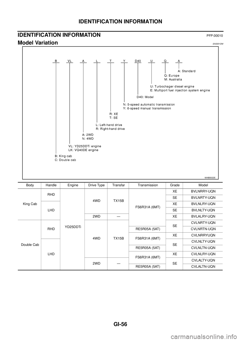
Model VariationEAS001DM
MAIB0022E
Body Handle Engine Drive Type Transfar Transmission Grade Model
King CabRHD
YD25DDTi4WD TX15B
FS6R31A (6MT)XE BVLNRRY-UQN
SE BVLNRTY-UQN
LHDXE BVLNLRY-UQN
SE BVLNLTY-UQN
2WD — XE BVLALRY-UQN
Double CabRHD
4WD TX15BSECVLNRTY-UQN
RE5R05A (5AT) CVLNRTN-UQN
FS6R31A (6MT)XE CVLNRRYUQN
LHDSECVLNLTY-UQN
RE5R05A (5AT) CVLNLTN-UQN
FS6R31A (6MT)XE CVLNLRY-UQN
2WD — SECVLALTY-UQN
RE5R05A (5AT) CVLALTN-UQN
Page 1680 of 3171
GI-58
IDENTIFICATION INFORMATION
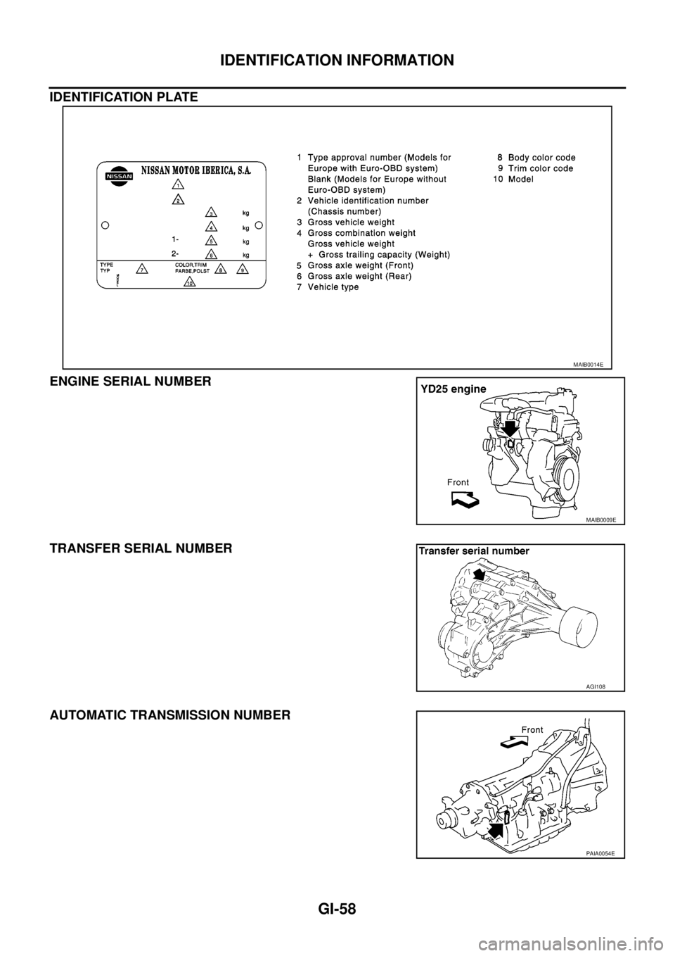
IDENTIFICATION PLATE
ENGINE SERIAL NUMBER
TRANSFER SERIAL NUMBER
AUTOMATIC TRANSMISSION NUMBER
MAIB0014E
MAIB0009E
AGI108
PAIA0054E
Page 1681 of 3171
IDENTIFICATION INFORMATION
GI-59
C
D
E
F
G
H
I
J
K
L
MB
GI
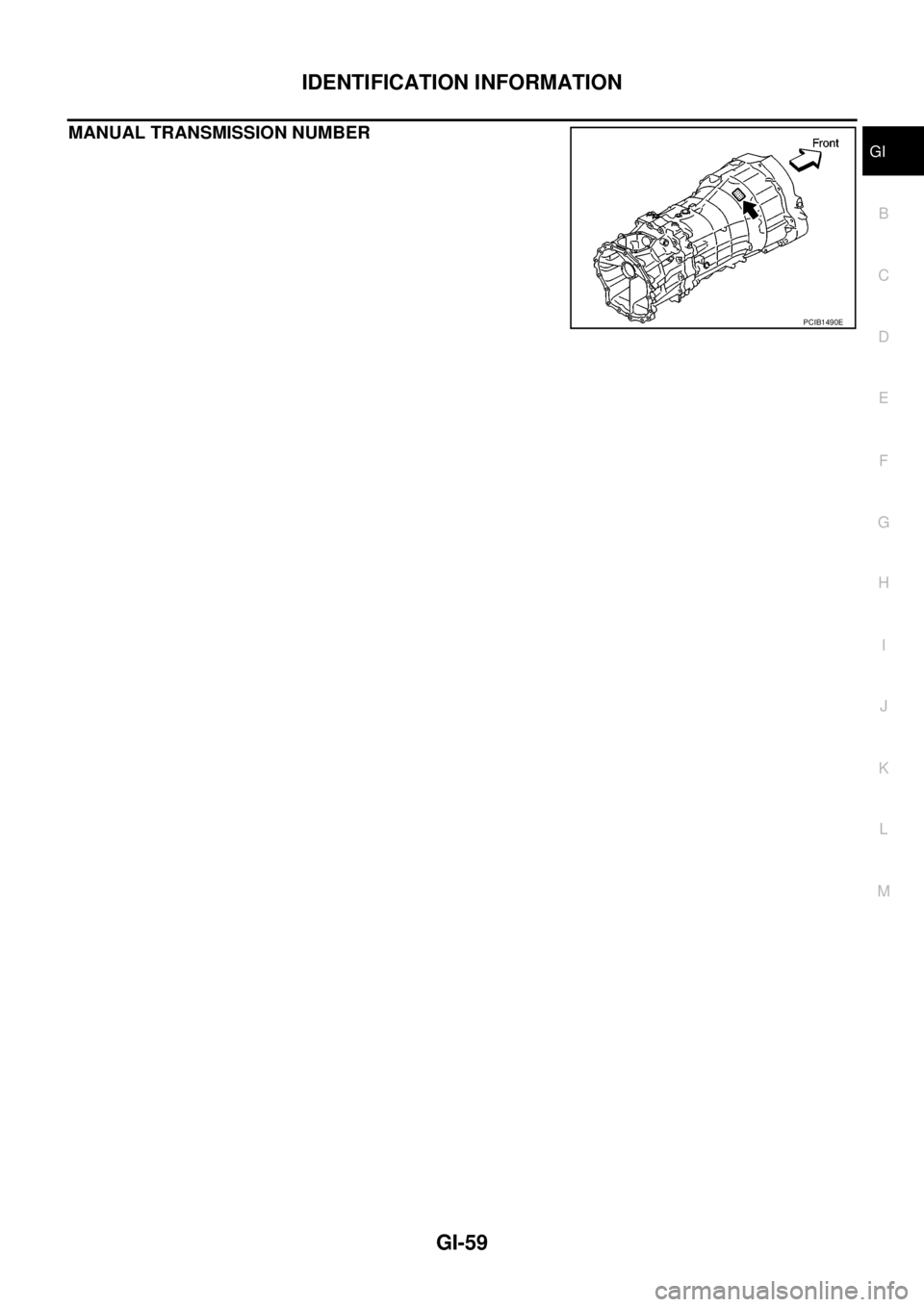
MANUAL TRANSMISSION NUMBER
PCIB1490E
Page 1686 of 3171

GI-64
TERMINOLOGY
***: Not applicableTransmission control module TCM A/T control unit
Turbocharger TC Turbocharger
Vehicle speed sensor VSS Vehicle speed sensor
Volume air flow sensor VAFS Air flow meter
Warm up oxidation catalyst WU-OC Catalyst
Warm up oxidation catalytic converter sys-
temWU-OC system ***
Warm up three way catalyst WU-TWC Catalyst
Warm up three way catalytic converter sys-
temWU-TWC system ***
Wide open throttle position switch WOTP switch Full switchNEW TERMNEW ACRONYM /
ABBREVIATIONOLD TERM
Page 1754 of 3171
IDX-2
ALPHABETICAL INDEX
Numerics
4LO indicator lamp .............................................TF-16
4LO switch ..............................................TF-56,TF-59
4WD - Wiring diagram .......................................TF-25
4WD shift indicator lamp ....................................TF-16
4WD shift switch .........................TF-16,TF-59,TF-62
4WD system description ....................................TF-15
4WD system diagram ........................................TF-18
4WD warning lamp ............................................TF-17
A
A/C air flow .......................................ATC-30
,MTC-30
A/C compressor clutch removal and installation ...........
ATC-143
,MTC-123
A/C compressor mounting ............ATC-142,MTC-122
A/C compressor precaution ..............ATC-12,MTC-12
A/C compressor special service tool .ATC-16,MTC-16
A/C control operation (auto A/C) .......ATC-28,MTC-28
A/C diagnostic work flow (auto A/C)ATC-103,MTC-95
A/C evaporator ..............................ATC-149,MTC-129
A/C HFC134a (R134a) system precaution .......ATC-4,
MTC-4
A/C HFC134a (R134a) system service procedure .......
ATC-138
,MTC-118
A/C HFC134a (R134a) system service tools ..ATC-16,
MTC-16
A/C HFC134a system service equipment precaution ...
ATC-12
,MTC-12
A/C lubricant (R134a) .......................ATC-24,MTC-24
A/C lubrication oil ..............................ATC-24,MTC-24
A/C operational check .......................ATC-57,MTC-53
A/C self-diagnoses (auto A/C) .......ATC-55,ATC-103,
MTC-51
,MTC-95
A/C service data specification .......ATC-154,MTC-135
A/C trouble diagnoses (auto A/C) .....ATC-33,MTC-33
A/C, A - Wiring diagram ....................ATC-39,MTC-39
A/T fluid checking ......................AT-12,AT-43,MA-29
A/T fluid replacement .............................AT-11,MA-31
A/T fluid temperature sensor ...........................AT-118
A/T IND - Wiring diagram ....................................DI-49
A/T indicator ........................................................DI-48
A/T self-diagnoses .............................................AT-89
A/T shift lock system ........................................AT-212
A/T trouble diagnoses ........................................AT-34
A/T Wiring diagram AT - CAN ............................AT-92
A/T Wiring diagram AT - FTS ..........................AT-119
A/T Wiring diagram AT - MAIN ........................AT-164
A/T Wiring diagram AT - NONDTC ..................AT-174
A/T Wiring diagram AT - PNP/SW ...................AT-100
A/T Wiring diagram AT - STSIG ........................AT-95
A/T Wiring diagram AT - VSS A/T ...................AT-105
ABS - Wiring diagram .....................................BRC-13
Accelerator control system ...............................ACC-2
Accelerator pedal position (APP) sensor ........EC-108,
EC-142
,EC-275
Aiming adjustment ..................................LT-28,LT-85
Air bag ..............................................................SRS-3
Air bag disposal ..............................................SRS-49
Air bleeding (hydraulic clutch) ..............................CL-8
Air cleaner and air duct .....................................EM-15
Air cleaner filter .................................................EM-17
Air cleaner filter replacement ............................MA-25
Air conditioner cut control ..................................EC-20
Air flow meter - See Mass air flow sensor ..........EC-92
Air mix. door motor .........................................ATC-68
Alternator ...........................................................SC-14
Ambient sensor .............................ATC-105,ATC-117
Angular tightening application .............................EM-4
APP2PW - Wiring diagram ..............................EC-229
APPS - Wiring diagram ....................................EC-110
APPS2 - Wiring diagram ..................................EC-144
APPS3 - Wiring diagram ..................................EC-277
ASC/BS - Wiring diagram ................................EC-192
ASC/SW - Wiring diagram ...............................EC-208
ASCBOF - Wiring diagram ...............................EC-331
ASCD ...............................................................EC-355
ASCD (automatic speed control device) ...........ACS-2
ASCD brake switch ...........................EC-189,EC-330
ASCD clutch switch ..........................EC-189,EC-330
ASCD indicator lamp .......................................EC-351
ASCD steering switch ......................................EC-206
ASCIND - Wiring diagram ................................EC-352
ATP switch ..............................................TF-82,TF-85
Auto air conditioner - Wiring diagramATC-39,MTC-39
Auto anti-dazzling inside mirror .......................GW-45
Autolamp ............................................................LT-49
Automatic amplifier ..........................ATC-60,MTC-55
Automatic transmission number ..............GI-58,GI-59
B
Back door trim .....................................................EI-30
BACK/L - Wiring diagram .................................LT-123
Back-up lamp ...................................................LT-123
Back-up lamp switch (M/T) ...................MT-12,MT-19
Ball joint (front) ................................................FSU-15
Barometric pressure (BARO) sensor ...............EC-293
Basic inspection .................................................EC-38
Battery .................................................................SC-5
Baulk ring (M/T) ................................................MT-21
BCM (Body control module) ..............................BCS-3
Blower motor ...ATC-80,ATC-121,MTC-71,MTC-100
Body mounting ....................................BL-189,BL-190
BOOST - Wiring diagram .................................EC-155
Brake booster ....................................................BR-19
Brake fluid level ................................................MA-35
Brake inspection ...............................................MA-35
Brake lines and cables inspection ....................MA-35
Brake master cylinder ........................................BR-17
Brake pedal ..........................................................BR-6
Brake switch ....................................................EC-330
Bulb specifications ...........................................LT-173
Bumper, front ......................................................EI-15
Bumper, rear .......................................................EI-17
Page 1759 of 3171
IDX-7
A
C
D
E
F
G
H
I
J
K
L B
IDX
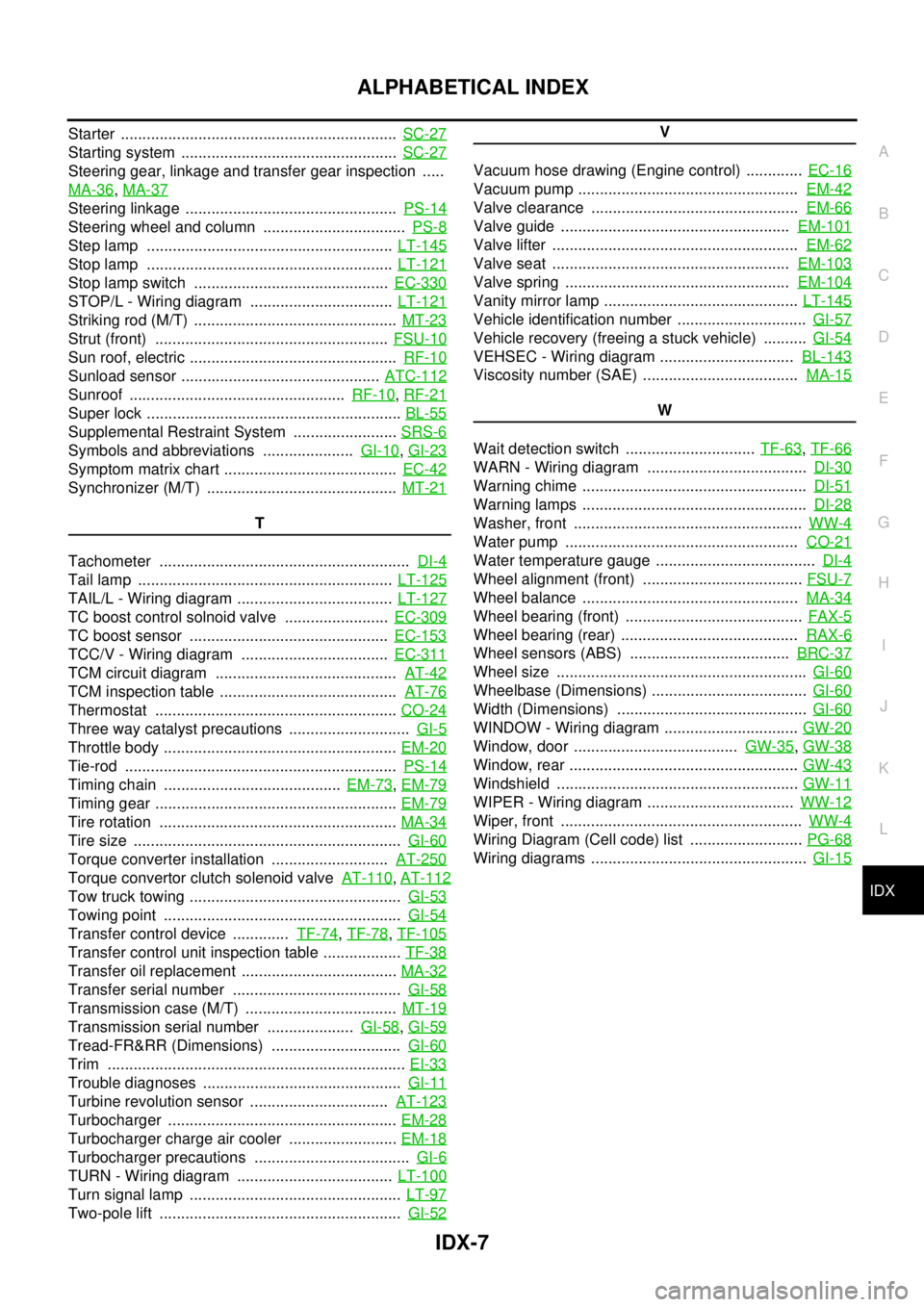
ALPHABETICAL INDEX
Starter ................................................................SC-27
Starting system ..................................................SC-27
Steering gear, linkage and transfer gear inspection .....
MA-36
,MA-37
Steering linkage .................................................PS-14
Steering wheel and column .................................PS-8
Step lamp .........................................................LT-145
Stop lamp .........................................................LT-121
Stop lamp switch .............................................EC-330
STOP/L - Wiring diagram .................................LT-121
Striking rod (M/T) ...............................................MT-23
Strut (front) ......................................................FSU-10
Sun roof, electric ................................................RF-10
Sunload sensor ..............................................ATC-112
Sunroof ..................................................RF-10,RF-21
Super lock ...........................................................BL-55
Supplemental Restraint System ........................SRS-6
Symbols and abbreviations .....................GI-10,GI-23
Symptom matrix chart ........................................EC-42
Synchronizer (M/T) ............................................MT-21
T
Tachometer ..........................................................DI-4
Tail lamp ...........................................................LT-125
TAIL/L - Wiring diagram ....................................LT-127
TC boost control solnoid valve ........................EC-309
TC boost sensor ..............................................EC-153
TCC/V - Wiring diagram ..................................EC-311
TCM circuit diagram ..........................................AT-42
TCM inspection table .........................................AT-76
Thermostat ........................................................CO-24
Three way catalyst precautions ............................GI-5
Throttle body ......................................................EM-20
Tie-rod ...............................................................PS-14
Timing chain .........................................EM-73,EM-79
Timing gear ........................................................EM-79
Tire rotation .......................................................MA-34
Tire size ..............................................................GI-60
Torque converter installation ...........................AT-250
Torque convertor clutch solenoid valveAT-110,AT-112
Tow truck towing .................................................GI-53
Towing point .......................................................GI-54
Transfer control device .............TF-74,TF-78,TF-105
Transfer control unit inspection table ..................TF-38
Transfer oil replacement ....................................MA-32
Transfer serial number .......................................GI-58
Transmission case (M/T) ...................................MT-19
Transmission serial number ....................GI-58,GI-59
Tread-FR&RR (Dimensions) ..............................GI-60
Trim .....................................................................EI-33
Trouble diagnoses ..............................................GI-11
Turbine revolution sensor ................................AT-123
Turbocharger .....................................................EM-28
Turbocharger charge air cooler .........................EM-18
Turbocharger precautions ....................................GI-6
TURN - Wiring diagram ....................................LT-100
Turn signal lamp .................................................LT-97
Two-pole lift ........................................................GI-52
V
Vacuum hose drawing (Engine control) .............EC-16
Vacuum pump ...................................................EM-42
Valve clearance ................................................EM-66
Valve guide .....................................................EM-101
Valve lifter .........................................................EM-62
Valve seat .......................................................EM-103
Valve spring ....................................................EM-104
Vanity mirror lamp .............................................LT-145
Vehicle identification number ..............................GI-57
Vehicle recovery (freeing a stuck vehicle) ..........GI-54
VEHSEC - Wiring diagram ...............................BL-143
Viscosity number (SAE) ....................................MA-15
W
Wait detection switch ..............................TF-63
,TF-66
WARN - Wiring diagram .....................................DI-30
Warning chime ....................................................DI-51
Warning lamps ....................................................DI-28
Washer, front .....................................................WW-4
Water pump ......................................................CO-21
Water temperature gauge .....................................DI-4
Wheel alignment (front) .....................................FSU-7
Wheel balance ..................................................MA-34
Wheel bearing (front) .........................................FAX-5
Wheel bearing (rear) .........................................RAX-6
Wheel sensors (ABS) .....................................BRC-37
Wheel size ..........................................................GI-60
Wheelbase (Dimensions) ....................................GI-60
Width (Dimensions) ............................................GI-60
WINDOW - Wiring diagram ...............................GW-20
Window, door ......................................GW-35,GW-38
Window, rear .....................................................GW-43
Windshield ........................................................GW-11
WIPER - Wiring diagram ..................................WW-12
Wiper, front ........................................................WW-4
Wiring Diagram (Cell code) list ..........................PG-68
Wiring diagrams ..................................................GI-15
Page 1792 of 3171
![NISSAN NAVARA 2005 Repair Workshop Manual TROUBLE DIAGNOSES WORK FLOW
LAN-15
[CAN]
C
D
E
F
G
H
I
J
L
MA
B
LAN
CAN Diagnostic Support MonitorEKS00LBJ
DESCRIPTION OF “CAN DIAG SUPPORT MNTR” SCREEN
FOR ECM
Display Results (Present)
lOK: Norm NISSAN NAVARA 2005 Repair Workshop Manual TROUBLE DIAGNOSES WORK FLOW
LAN-15
[CAN]
C
D
E
F
G
H
I
J
L
MA
B
LAN
CAN Diagnostic Support MonitorEKS00LBJ
DESCRIPTION OF “CAN DIAG SUPPORT MNTR” SCREEN
FOR ECM
Display Results (Present)
lOK: Norm](/img/5/57362/w960_57362-1791.png)
TROUBLE DIAGNOSES WORK FLOW
LAN-15
[CAN]
C
D
E
F
G
H
I
J
L
MA
B
LAN
CAN Diagnostic Support MonitorEKS00LBJ
DESCRIPTION OF “CAN DIAG SUPPORT MNTR” SCREEN
FOR ECM
Display Results (Present)
lOK: Normal
lNG: Malfunction
lUNKWN: The diagnosed unit does not transmit or receive the applicable data normally.
SKIB4863E
“SELECT SYSTEM”
screen“CAN DIAG SUPPORT
MNTR” screenDescription Present
ENGINEINITIAL DIAG Make sure that microcomputer in ECU works normally. OK/NG
TRANSMIT DIAG Make sure of normal transmission. OK/UNKWN
TCM Make sure of normal reception from TCM. OK/UNKWN
VDC/TCS/ABS VDC/TCS/ABS is not diagnosed. OK
METER/M&A Make sure of normal reception from combination meter. OK/UNKWN
BCM/SEC Make sure of normal reception from BCM. OK/UNKWN
HVACMake sure of normal reception from HVAC.
(Not available for CAN system diagnosis.)OK/UNKWN
Page 1793 of 3171
![NISSAN NAVARA 2005 Repair Workshop Manual LAN-16
[CAN]
TROUBLE DIAGNOSES WORK FLOW
DESCRIPTION OF “CAN DIAG SUPPORT MNTR” SCREEN
FOR TCM
Display Results (Present)
lOK: Normal
lNG: Malfunction
lUNKWN: The diagnosed unit does not transmit o NISSAN NAVARA 2005 Repair Workshop Manual LAN-16
[CAN]
TROUBLE DIAGNOSES WORK FLOW
DESCRIPTION OF “CAN DIAG SUPPORT MNTR” SCREEN
FOR TCM
Display Results (Present)
lOK: Normal
lNG: Malfunction
lUNKWN: The diagnosed unit does not transmit o](/img/5/57362/w960_57362-1792.png)
LAN-16
[CAN]
TROUBLE DIAGNOSES WORK FLOW
DESCRIPTION OF “CAN DIAG SUPPORT MNTR” SCREEN
FOR TCM
Display Results (Present)
lOK: Normal
lNG: Malfunction
lUNKWN: The diagnosed unit does not transmit or receive the applicable data normally.
SKIB2335E
“SELECT SYSTEM”
screen“CAN DIAG SUPPORT
MNTR” screenDescription Present
A/TINITIAL DIAG Make sure that microcomputer in ECU works normally. OK/NG
TRANSMIT DIAG Make sure of normal transmission. OK/UNKWN
ECM Make sure of normal reception from ECM. OK/UNKWN
VDC/TCS/ABS VDC/TCS/ABS is not diagnosed. OK
METER/M&A Make sure of normal reception from combination meter. OK/UNKWN
ICC/e4WD ICC/e4WD is not diagnosed. UNKWN
AWD/4WD Make sure of normal reception from transfer control unit. OK/UNKWN
Page 1795 of 3171
![NISSAN NAVARA 2005 Repair Workshop Manual LAN-18
[CAN]
TROUBLE DIAGNOSES WORK FLOW
DESCRIPTION OF “CAN DIAG SUPPORT MNTR” SCREEN
FOR DIFFERENTIAL LOCK CONTROL UNIT
Display Results (Present)
lOK: Normal
lNG: Malfunction
lUNKWN: The diagnos NISSAN NAVARA 2005 Repair Workshop Manual LAN-18
[CAN]
TROUBLE DIAGNOSES WORK FLOW
DESCRIPTION OF “CAN DIAG SUPPORT MNTR” SCREEN
FOR DIFFERENTIAL LOCK CONTROL UNIT
Display Results (Present)
lOK: Normal
lNG: Malfunction
lUNKWN: The diagnos](/img/5/57362/w960_57362-1794.png)
LAN-18
[CAN]
TROUBLE DIAGNOSES WORK FLOW
DESCRIPTION OF “CAN DIAG SUPPORT MNTR” SCREEN
FOR DIFFERENTIAL LOCK CONTROL UNIT
Display Results (Present)
lOK: Normal
lNG: Malfunction
lUNKWN: The diagnosed unit does not transmit or receive the applicable data normally.
PKIB7196E
“SELECT SYSTEM”
screen“CAN DIAG SUPPORT
MNTR” screenDescription Present
DIFF LOCKINITIAL DIAG Make sure that microcomputer in ECU works normally. OK/NG
TRANSMIT DIAG Make sure of normal transmission. OK/UNKWN
ECM Make sure of normal reception from ECM. OK/UNKWN
VDC/TCS/ABSMake sure of normal reception from ABS actuator and electric unit
(control unit).OK/UNKWN
AWD/4WD Make sure of normal reception from transfer control unit. OK/UNKWN
Page 1796 of 3171
![NISSAN NAVARA 2005 Repair Workshop Manual TROUBLE DIAGNOSES WORK FLOW
LAN-19
[CAN]
C
D
E
F
G
H
I
J
L
MA
B
LAN
DESCRIPTION OF “CAN DIAG SUPPORT MNTR” SCREEN FOR FRONT AIR CONTROL
Display Results (Present)
lOK: Normal
lUNKWN: The diagnosed NISSAN NAVARA 2005 Repair Workshop Manual TROUBLE DIAGNOSES WORK FLOW
LAN-19
[CAN]
C
D
E
F
G
H
I
J
L
MA
B
LAN
DESCRIPTION OF “CAN DIAG SUPPORT MNTR” SCREEN FOR FRONT AIR CONTROL
Display Results (Present)
lOK: Normal
lUNKWN: The diagnosed](/img/5/57362/w960_57362-1795.png)
TROUBLE DIAGNOSES WORK FLOW
LAN-19
[CAN]
C
D
E
F
G
H
I
J
L
MA
B
LAN
DESCRIPTION OF “CAN DIAG SUPPORT MNTR” SCREEN FOR FRONT AIR CONTROL
Display Results (Present)
lOK: Normal
lUNKWN: The diagnosed unit does not transmit or receive the applicable data normally.
l–: There is no received unit or the unit is not in the condition that reception diagnosis is performed.
Display Results (Past)
lOK: Normal
l0: There is malfunction now.
l1 ~ 39: Displays when it is normal at present and finds malfunction in the past. It increases like 0®1®2...38®39 after returning to the
normal condition whenever IGN OFF®ON. If it is over 39, it is fixed to 39 until the self-diagnostic results are erased. It returns to 0
when malfunction is detected again in the process.
l–: Undiagnosed
PKIC2531E
“SELECT SYSTEM”
screen“CAN DIAG SUPPORT
MNTR” screenDescription Present Past
HVACTRANSMIT DIAG Make sure of normal transmission. OK/UNKWN/–
OK/0/1~39/– ECM Make sure of normal reception from ECM. OK/UNKWN/–
TCM TCM is not diagnosed. –
BCM/SEC Make sure of normal reception from BCM. OK/UNKWN/–
VDC/TCS/ABSMake sure of normal reception from ABS actua-
tor and electric unit (control unit).OK/UNKWN/–
IPDM E/R Make sure of normal reception from IPDM E/R. OK/UNKWN/–
DISPLAY DISPLAY is not diagnosed. –
I-KEY I-KEY is not diagnosed. –
EPS EPS is not diagnosed. –
AWD/4WD AWD/4WD is not diagnosed. –
e4WD e4WD is not diagnosed. –
ICC ICC is not diagnosed. –
LANE KEEP LANE KEEP is not diagnosed. –
TIRE-P TIRE-P is not diagnosed. –