coolant level NISSAN NAVARA 2005 Repair User Guide
[x] Cancel search | Manufacturer: NISSAN, Model Year: 2005, Model line: NAVARA, Model: NISSAN NAVARA 2005Pages: 3171, PDF Size: 49.59 MB
Page 1120 of 3171
EC-140
DTC P0217 ENGINE OVER TEMPERATURE
5.CHECK COOLING FAN MOTOR
Refer toEC-141, "
Component Inspection".
OK or NG
OK >> GO TO 6.
NG >> Replace cooling fan motors.
6.CHECK INTERMITTENT INCIDENT
PerformEC-70, "
TROUBLE DIAGNOSIS FOR INTERMITTENT INCIDENT".
OK or NG
OK >> Replace IPDM E/R. Refer toPG-14, "IPDM E/R (INTELLIGENT POWER DISTRIBUTION MOD-
ULE ENGINE ROOM)".
NG >> Repair or replace harness or connector.
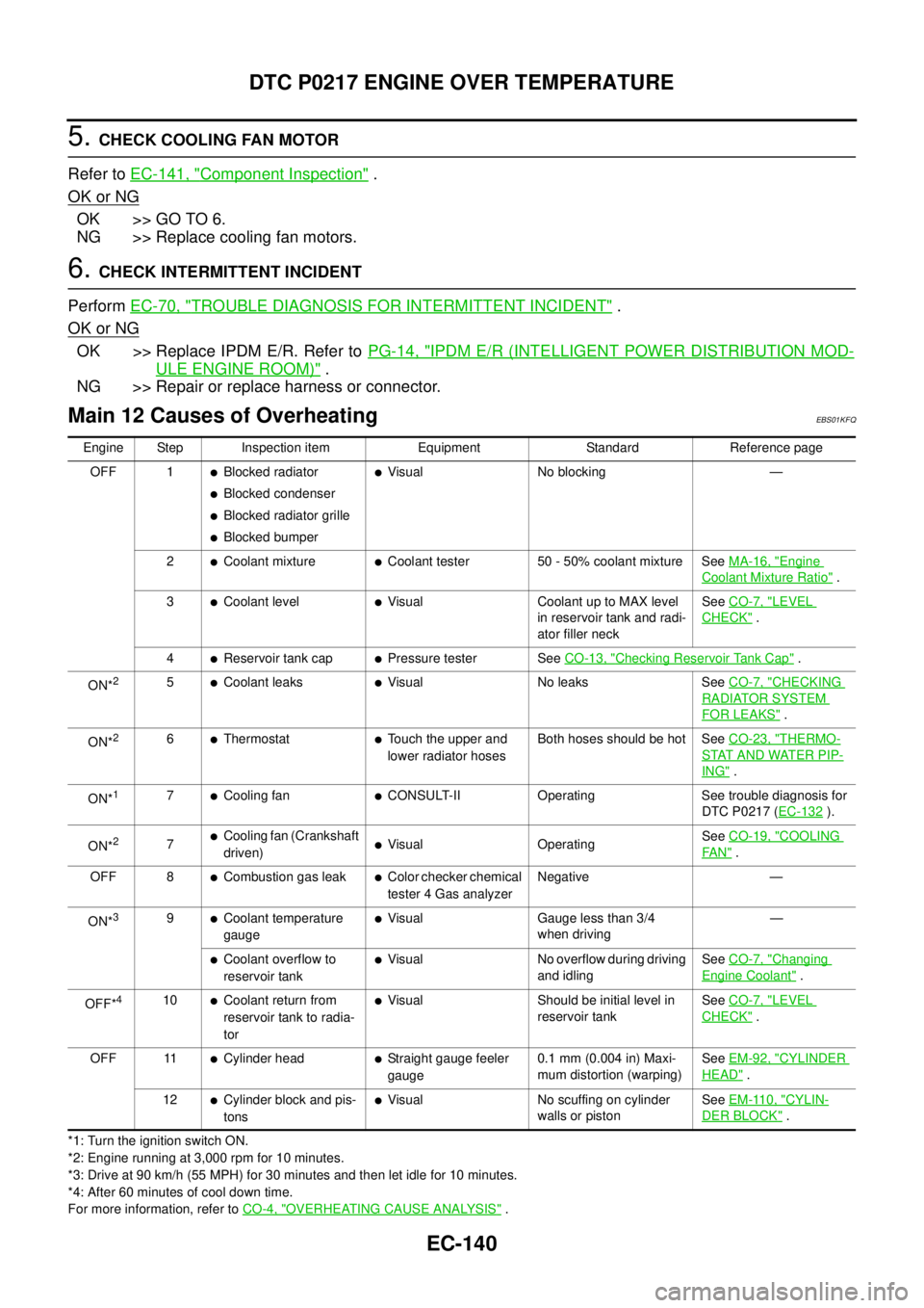
Main 12 Causes of OverheatingEBS01KFQ
*1: Turn the ignition switch ON.
*2: Engine running at 3,000 rpm for 10 minutes.
*3: Drive at 90 km/h (55 MPH) for 30 minutes and then let idle for 10 minutes.
*4: After 60 minutes of cool down time.
For more information, refer toCO-4, "
OVERHEATING CAUSE ANALYSIS". Engine Step Inspection item Equipment Standard Reference page
OFF 1
lBlocked radiator
lBlocked condenser
lBlocked radiator grille
lBlocked bumper
lVisual No blocking —
2
lCoolant mixturelCoolant tester 50 - 50% coolant mixture SeeMA-16, "Engine
Coolant Mixture Ratio".
3
lCoolant levellVisual Coolant up to MAX level
in reservoir tank and radi-
ator filler neckSeeCO-7, "LEVEL
CHECK".
4
lReservoir tank caplPressure tester SeeCO-13, "Checking Reservoir Tank Cap".
ON*
25lCoolant leakslVisual No leaks SeeCO-7, "CHECKING
RADIATOR SYSTEM
FOR LEAKS".
ON*
26lThermostatlTouch the upper and
lower radiator hosesBoth hoses should be hot SeeCO-23, "THERMO-
STAT AND WATER PIP-
ING".
ON*
17lCooling fanlCONSULT-II Operating See trouble diagnosis for
DTC P0217 (EC-132
).
ON*
27lCooling fan (Crankshaft
driven)lVisual OperatingSeeCO-19, "COOLING
FA N".
OFF 8
lCombustion gas leaklColor checker chemical
tester 4 Gas analyzerNegative —
ON*
39lCoolant temperature
gaugelVisual Gauge less than 3/4
when driving—
lCoolant overflow to
reservoir tanklVisual No overflow during driving
and idlingSeeCO-7, "Changing
Engine Coolant".
OFF*
410lCoolant return from
reservoir tank to radia-
torlVisual Should be initial level in
reservoir tankSeeCO-7, "LEVEL
CHECK".
OFF 11
lCylinder headlStraight gauge feeler
gauge0.1 mm (0.004 in) Maxi-
mum distortion (warping)SeeEM-92, "CYLINDER
HEAD".
12
lCylinder block and pis-
tonslVisual No scuffing on cylinder
walls or pistonSeeEM-110, "CYLIN-
DER BLOCK".
Page 1277 of 3171
GLOW CONTROL SYSTEM
EC-297
C
D
E
F
G
H
I
J
K
L
MA
EC
Diagnostic ProcedureEBS01KLO
1.INSPECTION START
Check fuel level, fuel supplying system, starter motor, etc.
OK or NG
OK >> GO TO 2.
NG >> Correct.
2.CHECK INSTALLATION
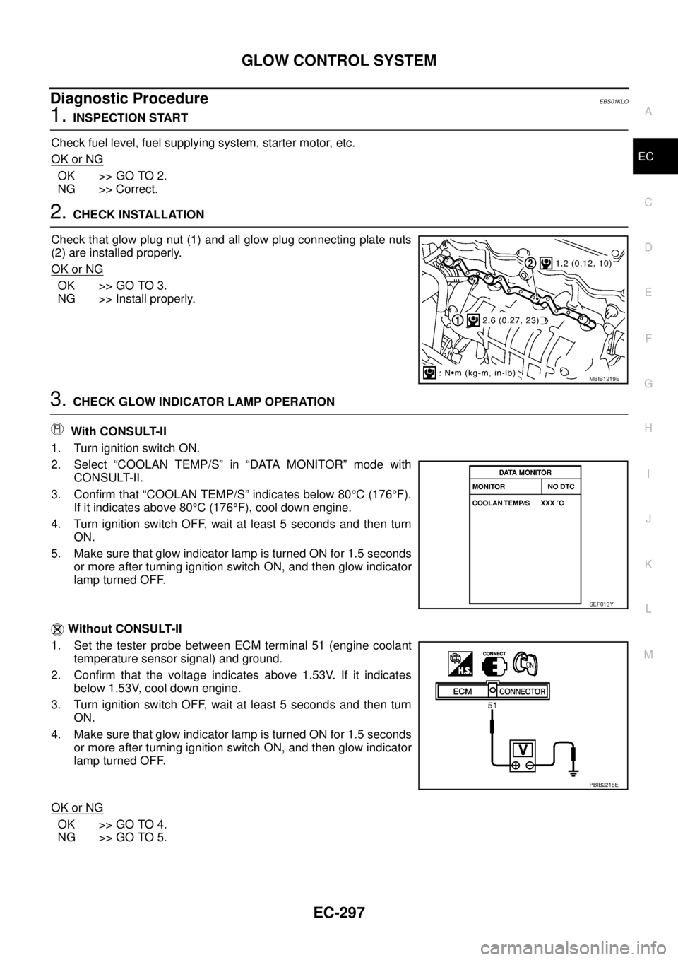
Check that glow plug nut (1) and all glow plug connecting plate nuts
(2) are installed properly.
OK or NG
OK >> GO TO 3.
NG >> Install properly.
3.CHECK GLOW INDICATOR LAMP OPERATION
With CONSULT-II
1. Turn ignition switch ON.
2. Select “COOLAN TEMP/S” in “DATA MONITOR” mode with
CONSULT-II.
3. Confirm that “COOLAN TEMP/S” indicates below 80°C(176°F).
If it indicates above 80°C(176°F), cool down engine.
4. Turn ignition switch OFF, wait at least 5 seconds and then turn
ON.
5. Make sure that glow indicator lamp is turned ON for 1.5 seconds
or more after turning ignition switch ON, and then glow indicator
lamp turned OFF.
Without CONSULT-II
1. Set the tester probe between ECM terminal 51 (engine coolant
temperature sensor signal) and ground.
2. Confirm that the voltage indicates above 1.53V. If it indicates
below 1.53V, cool down engine.
3. Turn ignition switch OFF, wait at least 5 seconds and then turn
ON.
4. Make sure that glow indicator lamp is turned ON for 1.5 seconds
or more after turning ignition switch ON, and then glow indicator
lamp turned OFF.
OK or NG
OK >> GO TO 4.
NG >> GO TO 5.
MBIB1219E
SEF013Y
PBIB2216E
Page 1403 of 3171
INTAKE MANIFOLD
EM-21
C
D
E
F
G
H
I
J
K
L
MA
EM
lRefer toGI-10, "Components"for symbol marks except in the above.
Removal and InstallationEBS01EJF
REMOVAL
WARNING:
To avoid the danger of being scalded, do not drain engine coolant when engine is hot.
1. Drain engine coolant. Refer toCO-7, "
Changing Engine Coolant".
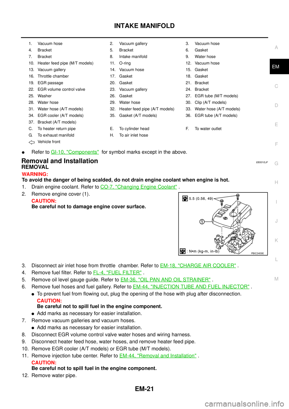
2. Remove engine cover (1).
CAUTION:
Be careful not to damage engine cover surface.
3. Disconnect air inlet hose from throttle chamber. Refer toEM-18, "
CHARGE AIR COOLER".
4. Remove fuel filter. Refer toFL-4, "
FUEL FILTER".
5. Remove oil level gauge guide. Refer toEM-36, "
OIL PAN AND OIL STRAINER".
6. Remove fuel hoses and fuel gallery. Refer toEM-44, "
INJECTION TUBE AND FUEL INJECTOR".
lTo prevent fuel from flowing out, plug the opening of the hose with plug after disconnection.
CAUTION:
Be careful not to spill fuel in the engine component.
lAdd marks as necessary for easier installation.
7. Remove vacuum galleries and vacuum hoses.
lAdd marks as necessary for easier installation.
8. Disconnect EGR volume control valve water hoses and wiring harness.
9. Disconnect heater feed hose, water hoses, and remove heater feed pipe.
10. Remove EGR cooler (A/T models) or EGR tube (M/T models).
11. Remove injection tube center. Refer toEM-44, "
Removal and Installation".
CAUTION:
Be careful not to spill fuel in the engine component.
12. Remove water pipe.
1. Vacuum hose 2. Vacuum gallery 3. Vacuum hose
4. Bracket 5. Bracket 6. Gasket
7. Bracket 8. Intake manifold 9. Water hose
10. Heater feed pipe (M/T models) 11. O-ring 12. Vacuum hose
13. Vacuum gallery 14. Vacuum hose 15. Gasket
16. Throttle chamber 17. Gasket 18. Gasket
19. EGR passage 20. Gasket 21. Bracket
22. EGR volume control valve 23. Vacuum gallery 24. Bracket
25. Washer 26. Gasket 27. EGR tube (M/T models)
28. Water hose 29. Water hose 30. Clip (A/T models)
31. Water hose (A/T models) 32. Heater feed pipe (A/T models) 33. Water hose (A/T models)
34. EGR cooler (A/T models) 35. Gasket (A/T models) 36. EGR tube (A/T models)
37. Bracket (A/T models)
C. To heater return pipe E. To cylinder head F. To water outlet
G. To exhaust manifold H. To air inlet hose
Vehicle front
PBIC3409E
Page 1447 of 3171
CAMSHAFT
EM-65
C
D
E
F
G
H
I
J
K
L
MA
EM
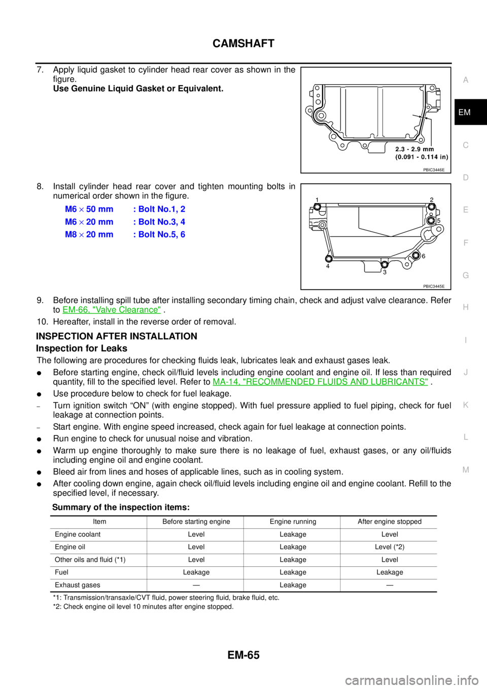
7. Apply liquid gasket to cylinder head rear cover as shown in the
figure.
Use Genuine Liquid Gasket or Equivalent.
8. Install cylinder head rear cover and tighten mounting bolts in
numerical order shown in the figure.
9. Before installing spill tube after installing secondary timing chain, check and adjust valve clearance. Refer
toEM-66, "
Valve Clearance".
10. Hereafter, install in the reverse order of removal.
INSPECTION AFTER INSTALLATION
Inspection for Leaks
The following are procedures for checking fluids leak, lubricates leak and exhaust gases leak.
lBefore starting engine, check oil/fluid levels including engine coolant and engine oil. If less than required
quantity, fill to the specified level. Refer toMA-14, "
RECOMMENDED FLUIDS AND LUBRICANTS".
lUse procedure below to check for fuel leakage.
–Turn ignition switch “ON” (with engine stopped). With fuel pressure applied to fuel piping, check for fuel
leakage at connection points.
–Start engine. With engine speed increased, check again for fuel leakage at connection points.
lRun engine to check for unusual noise and vibration.
lWarm up engine thoroughly to make sure there is no leakage of fuel, exhaust gases, or any oil/fluids
including engine oil and engine coolant.
lBleed air from lines and hoses of applicable lines, such as in cooling system.
lAfter cooling down engine, again check oil/fluid levels including engine oil and engine coolant. Refill to the
specified level, if necessary.
Summary of the inspection items:
*1: Transmission/transaxle/CVT fluid, power steering fluid, brake fluid, etc.
*2: Check engine oil level 10 minutes after engine stopped.
PBIC3446E
M6´50 mm : Bolt No.1, 2
M6´20 mm : Bolt No.3, 4
M8´20 mm : Bolt No.5, 6
PBIC3445E
Item Before starting engine Engine running After engine stopped
Engine coolant Level Leakage Level
Engine oil Level Leakage Level (*2)
Other oils and fluid (*1) Level Leakage Level
Fuel Leakage Leakage Leakage
Exhaust gases — Leakage —
Page 1459 of 3171
SECONDARY TIMING CHAIN
EM-77
C
D
E
F
G
H
I
J
K
L
MA
EM
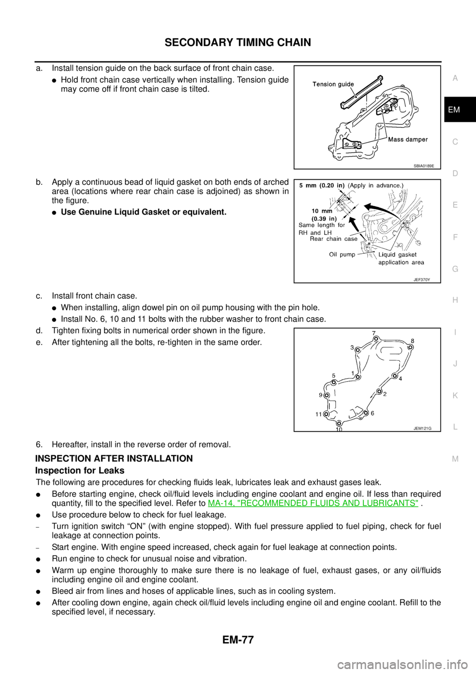
a. Install tension guide on the back surface of front chain case.
lHold front chain case vertically when installing. Tension guide
may come off if front chain case is tilted.
b. Apply a continuous bead of liquid gasket on both ends of arched
area (locations where rear chain case is adjoined) as shown in
the figure.
lUse Genuine Liquid Gasket or equivalent.
c. Install front chain case.
lWhen installing, align dowel pin on oil pump housing with the pin hole.
lInstall No. 6, 10 and 11 bolts with the rubber washer to front chain case.
d. Tighten fixing bolts in numerical order shown in the figure.
e. After tightening all the bolts, re-tighten in the same order.
6. Hereafter, install in the reverse order of removal.
INSPECTION AFTER INSTALLATION
Inspection for Leaks
The following are procedures for checking fluids leak, lubricates leak and exhaust gases leak.
lBefore starting engine, check oil/fluid levels including engine coolant and engine oil. If less than required
quantity, fill to the specified level. Refer toMA-14, "
RECOMMENDED FLUIDS AND LUBRICANTS".
lUse procedure below to check for fuel leakage.
–Turn ignition switch “ON” (with engine stopped). With fuel pressure applied to fuel piping, check for fuel
leakage at connection points.
–Start engine. With engine speed increased, check again for fuel leakage at connection points.
lRun engine to check for unusual noise and vibration.
lWarm up engine thoroughly to make sure there is no leakage of fuel, exhaust gases, or any oil/fluids
including engine oil and engine coolant.
lBleed air from lines and hoses of applicable lines, such as in cooling system.
lAfter cooling down engine, again check oil/fluid levels including engine oil and engine coolant. Refill to the
specified level, if necessary.
SBIA0189E
JEF370Y
JEM121G
Page 1460 of 3171

EM-78
SECONDARY TIMING CHAIN
Summary of the inspection items:
*1: Transmission/transaxle/CVT fluid, power steering fluid, brake fluid, etc.
*2: Check engine oil level 10 minutes after engine stopped.Item Before starting engine Engine running After engine stopped
Engine coolant Level Leakage Level
Engine oil Level Leakage Level (*2)
Other oils and fluid (*1) Level Leakage Level
Fuel Leakage Leakage Leakage
Exhaust gases — Leakage —
Page 1473 of 3171
PRIMARY TIMING CHAIN
EM-91
C
D
E
F
G
H
I
J
K
L
MA
EM
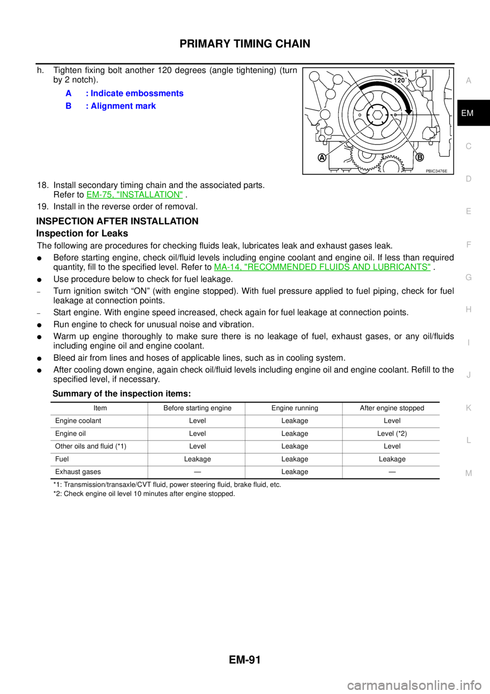
h. Tighten fixing bolt another 120 degrees (angle tightening) (turn
by 2 notch).
18. Install secondary timing chain and the associated parts.
Refer toEM-75, "
INSTALLATION".
19. Install in the reverse order of removal.
INSPECTION AFTER INSTALLATION
Inspection for Leaks
The following are procedures for checking fluids leak, lubricates leak and exhaust gases leak.
lBefore starting engine, check oil/fluid levels including engine coolant and engine oil. If less than required
quantity, fill to the specified level. Refer toMA-14, "
RECOMMENDED FLUIDS AND LUBRICANTS".
lUse procedure below to check for fuel leakage.
–Turn ignition switch “ON” (with engine stopped). With fuel pressure applied to fuel piping, check for fuel
leakage at connection points.
–Start engine. With engine speed increased, check again for fuel leakage at connection points.
lRun engine to check for unusual noise and vibration.
lWarm up engine thoroughly to make sure there is no leakage of fuel, exhaust gases, or any oil/fluids
including engine oil and engine coolant.
lBleed air from lines and hoses of applicable lines, such as in cooling system.
lAfter cooling down engine, again check oil/fluid levels including engine oil and engine coolant. Refill to the
specified level, if necessary.
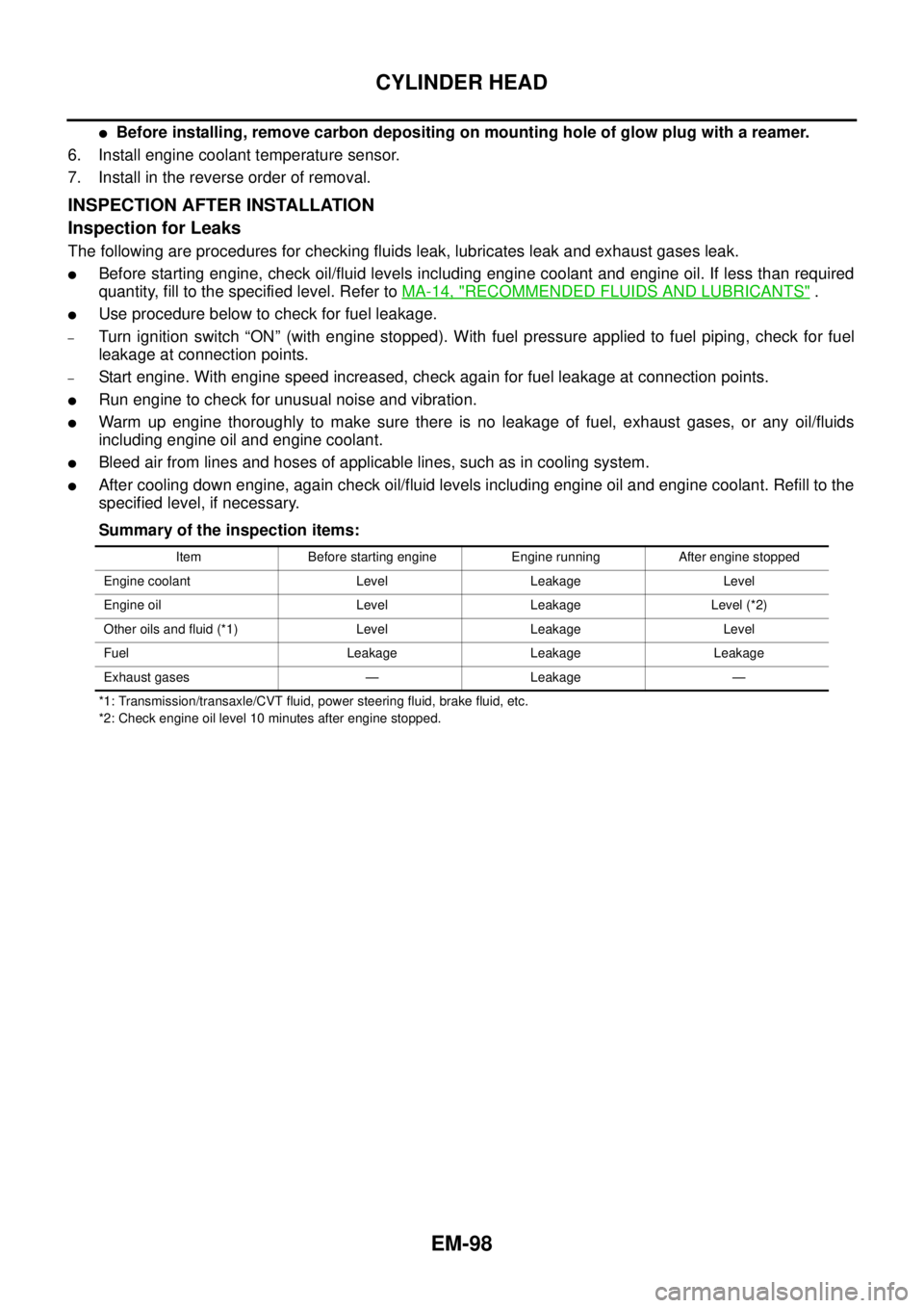
Summary of the inspection items:
*1: Transmission/transaxle/CVT fluid, power steering fluid, brake fluid, etc.
*2: Check engine oil level 10 minutes after engine stopped.
A : Indicate embossments
B : Alignment mark
PBIC3476E
Item Before starting engine Engine running After engine stopped
Engine coolant Level Leakage Level
Engine oil Level Leakage Level (*2)
Other oils and fluid (*1) Level Leakage Level
Fuel Leakage Leakage Leakage
Exhaust gases — Leakage —
Page 1480 of 3171
EM-98
CYLINDER HEAD
lBefore installing, remove carbon depositing on mounting hole of glow plug with a reamer.
6. Install engine coolant temperature sensor.
7. Install in the reverse order of removal.
INSPECTION AFTER INSTALLATION
Inspection for Leaks
The following are procedures for checking fluids leak, lubricates leak and exhaust gases leak.
lBefore starting engine, check oil/fluid levels including engine coolant and engine oil. If less than required
quantity, fill to the specified level. Refer toMA-14, "
RECOMMENDED FLUIDS AND LUBRICANTS".
lUse procedure below to check for fuel leakage.
–Turn ignition switch “ON” (with engine stopped). With fuel pressure applied to fuel piping, check for fuel
leakage at connection points.
–Start engine. With engine speed increased, check again for fuel leakage at connection points.
lRun engine to check for unusual noise and vibration.
lWarm up engine thoroughly to make sure there is no leakage of fuel, exhaust gases, or any oil/fluids
including engine oil and engine coolant.
lBleed air from lines and hoses of applicable lines, such as in cooling system.
lAfter cooling down engine, again check oil/fluid levels including engine oil and engine coolant. Refill to the
specified level, if necessary.
Summary of the inspection items:
*1: Transmission/transaxle/CVT fluid, power steering fluid, brake fluid, etc.
*2: Check engine oil level 10 minutes after engine stopped.Item Before starting engine Engine running After engine stopped
Engine coolant Level Leakage Level
Engine oil Level Leakage Level (*2)
Other oils and fluid (*1) Level Leakage Level
Fuel Leakage Leakage Leakage
Exhaust gases — Leakage —
Page 1490 of 3171
EM-108
ENGINE ASSEMBLY
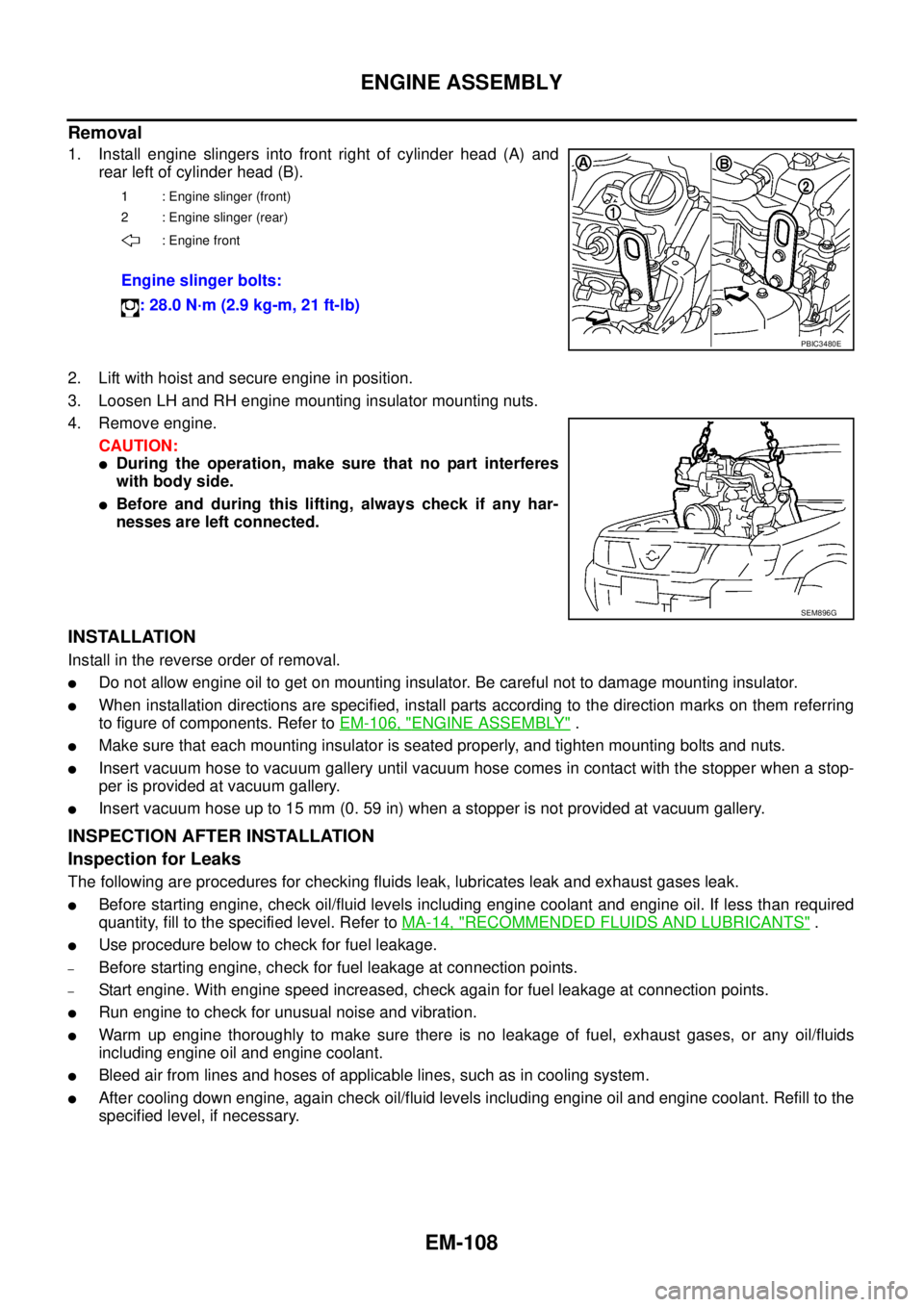
Removal
1. Install engine slingers into front right of cylinder head (A) and
rear left of cylinder head (B).
2. Lift with hoist and secure engine in position.
3. Loosen LH and RH engine mounting insulator mounting nuts.
4. Remove engine.
CAUTION:
lDuring the operation, make sure that no part interferes
with body side.
lBefore and during this lifting, always check if any har-
nesses are left connected.
INSTALLATION
Install in the reverse order of removal.
lDo not allow engine oil to get on mounting insulator. Be careful not to damage mounting insulator.
lWhen installation directions are specified, install parts according to the direction marks on them referring
to figure of components. Refer toEM-106, "
ENGINE ASSEMBLY".
lMake sure that each mounting insulator is seated properly, and tighten mounting bolts and nuts.
lInsert vacuum hose to vacuum gallery until vacuum hose comes in contact with the stopper when a stop-
per is provided at vacuum gallery.
lInsert vacuum hose up to 15 mm (0. 59 in) when a stopper is not provided at vacuum gallery.
INSPECTION AFTER INSTALLATION
Inspection for Leaks
The following are procedures for checking fluids leak, lubricates leak and exhaust gases leak.
lBefore starting engine, check oil/fluid levels including engine coolant and engine oil. If less than required
quantity, fill to the specified level. Refer toMA-14, "
RECOMMENDED FLUIDS AND LUBRICANTS".
lUse procedure below to check for fuel leakage.
–Before starting engine, check for fuel leakage at connection points.
–Start engine. With engine speed increased, check again for fuel leakage at connection points.
lRun engine to check for unusual noise and vibration.
lWarm up engine thoroughly to make sure there is no leakage of fuel, exhaust gases, or any oil/fluids
including engine oil and engine coolant.
lBleed air from lines and hoses of applicable lines, such as in cooling system.
lAfter cooling down engine, again check oil/fluid levels including engine oil and engine coolant. Refill to the
specified level, if necessary.
1 : Engine slinger (front)
2 : Engine slinger (rear)
: Engine front
Engine slinger bolts:
: 28.0 N·m (2.9 kg-m, 21 ft-lb)
PBIC3480E
SEM896G
Page 1491 of 3171
ENGINE ASSEMBLY
EM-109
C
D
E
F
G
H
I
J
K
L
MA
EM
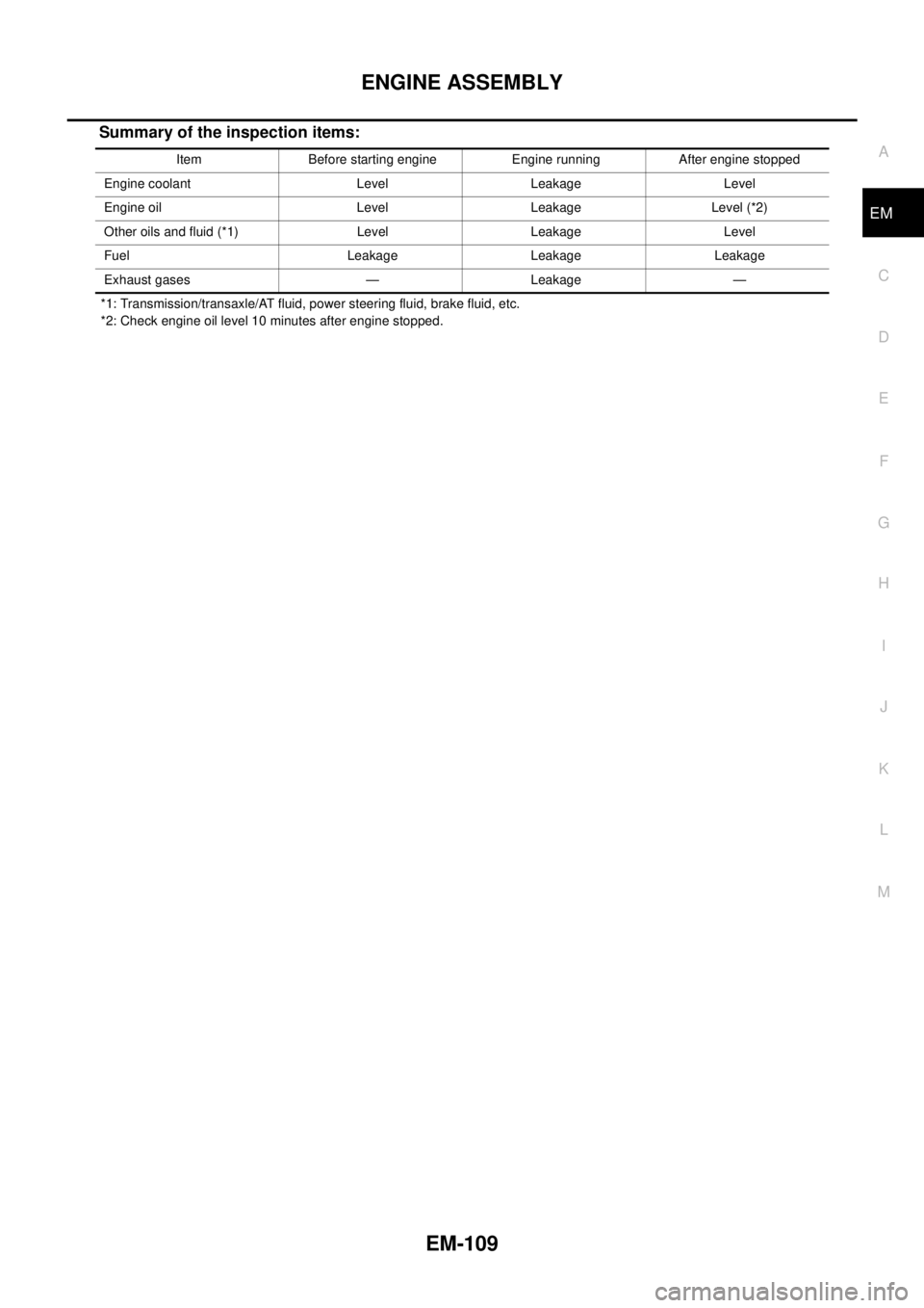
Summary of the inspection items:
*1: Transmission/transaxle/AT fluid, power steering fluid, brake fluid, etc.
*2: Check engine oil level 10 minutes after engine stopped.Item Before starting engine Engine running After engine stopped
Engine coolant Level Leakage Level
Engine oil Level Leakage Level (*2)
Other oils and fluid (*1) Level Leakage Level
Fuel Leakage Leakage Leakage
Exhaust gases — Leakage —