engine coolant NISSAN NAVARA 2005 Repair Owner's Manual
[x] Cancel search | Manufacturer: NISSAN, Model Year: 2005, Model line: NAVARA, Model: NISSAN NAVARA 2005Pages: 3171, PDF Size: 49.59 MB
Page 909 of 3171
THERMOSTAT AND WATER PIPING
CO-25
C
D
E
F
G
H
I
J
K
L
MA
CO
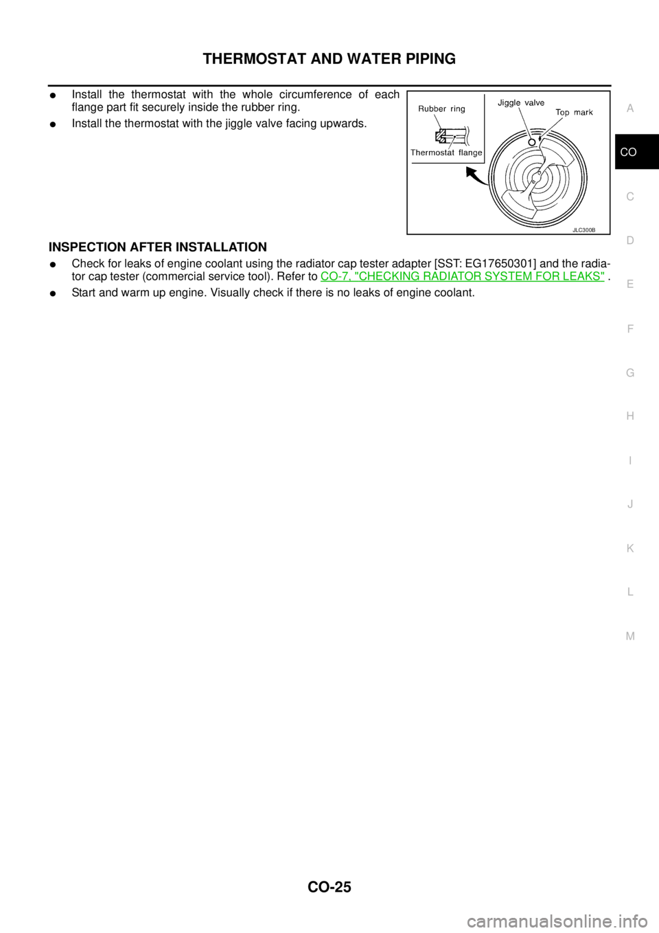
lInstall the thermostat with the whole circumference of each
flange part fit securely inside the rubber ring.
lInstall the thermostat with the jiggle valve facing upwards.
INSPECTION AFTER INSTALLATION
lCheck for leaks of engine coolant using the radiator cap tester adapter [SST: EG17650301] and the radia-
tor cap tester (commercial service tool). Refer toCO-7, "
CHECKING RADIATOR SYSTEM FOR LEAKS".
lStart and warm up engine. Visually check if there is no leaks of engine coolant.
JLC300B
Page 910 of 3171

CO-26
SERVICE DATA AND SPECIFICATIONS (SDS)
SERVICE DATA AND SPECIFICATIONS (SDS)
PFP:00030
Standard and LimitEBS01E6Y
ENGINE COOLANT CAPACITY
Unit: (lmp qt)
THERMOSTAT
RESERVOIR TANK
Unit:kPa(bar,kg/cm2, psi)
Engine coolant capacity
(With reservoir tank at “MAX” level)LHD models Approx. 9.9 (8-3/4)
RHD models Approx. 10.2 (9)
Reservoir tank (at “MAX” level)0.8 (3/4)
Valve opening temperature 80.5 - 83.5°C (177 - 182°F)
Full open lift amount More than 9 mm/ 95°C (0.35 in/203°F)
Valve closing temperature More than 77°C(171°F)
Cap relief pressureStandard 98.2 - 117.8 (0.98 - 1.18, 1.0 - 1.2, 14 - 17)
Limit 59 (0.59, 0.6, 9)
Leakage test pressure 157 (1.57, 1.6, 23)
Page 911 of 3171

DI-1
DRIVER INFORMATION SYSTEM
K ELECTRICAL
CONTENTS
C
D
E
F
G
H
I
J
L
M
SECTIONDI
A
B
DI
DRIVER INFORMATION SYSTEM
PRECAUTION ............................................................ 3
Precautions for Supplemental Restraint System
(SRS)“AIRBAG”and“SEATBELTPRE-TEN-
SIONER” .................................................................. 3
Wiring Diagrams and Trouble Diagnosis .................. 3
COMBINATION METERS ........................................... 4
System Description .................................................. 4
UNIFIED METER CONTROL UNIT ...................... 4
POWER SUPPLY AND GROUND CIRCUIT ........ 4
SPEEDOMETER ................................................... 4
TACHOMETER ..................................................... 4
WATER TEMPERATURE GAUGE ........................ 4
FUEL GAUGE ....................................................... 5
ODO/TRIP METER ............................................... 5
TRIP COMPUTER ................................................ 5
ENGINE OIL MAINTENANCE INFORMATION..... 6
METER ILLUMINATION CONTROL ..................... 6
CLOCK .................................................................. 6
AMBIENT AIR TEMPERATURE INDICATION ...... 6
Component Parts and Harness Connector Location..... 7
Arrangement of Combination Meter ......................... 8
Internal Circuit .......................................................... 9
Wiring Diagram — METER — ................................ 10
Terminals and Reference Value for Combination
Meter ...................................................................... 12
Self-Diagnosis Mode of Combination Meter ........... 13
FUNCTION .......................................................... 13
OPERATION PROCEDURE ............................... 13
TEST ITEM ......................................................... 13
CONSULT-II Function (METER) ............................. 15
CONSULT-II BASIC OPERATION ....................... 15
SELF-DIAG RESULTS ........................................ 16
DATA MONITOR ................................................. 17
Trouble Diagnosis .................................................. 18
HOW TO PERFORM TROUBLE DIAGNOSIS ... 18
PRELIMINARY CHECK ...................................... 19
Symptom Chart ...................................................... 19
Power Supply and Ground Circuit Inspection ........ 19
Vehicle Speed Signal Inspection ............................ 20
Engine Speed Signal Inspection ............................ 21Engine Coolant Temperature Signal Inspection ..... 21
Fuel Level Sensor Signal Inspection ...................... 22
Ambient Sensor Signal Inspection .......................... 24
Fuel Gauge Fluctuates, Indicates Wrong Value, or
Varies ...................................................................... 25
Fuel Gauge Does Not Move to Full position ........... 25
DTC [U1000] CAN Communication Circuit ............. 26
DTC [B2205] Vehicle Speed Circuit ........................ 26
Electrical Components Inspection .......................... 27
FUEL LEVEL SENSOR UNIT CHECK ................ 27
AMBIENT SENSOR CHECK ............................... 27
Removal and Installation of Combination Meter ..... 27
WARNING LAMPS .................................................... 28
System Description ................................................. 28
OIL PRESSURE WARNING LAMP ..................... 28
Component Parts and Harness Connector Location... 28
Schematic ............................................................... 29
Wiring Diagram — WARN — .................................. 30
A/T MODELS ....................................................... 30
M/T MODELS ...................................................... 37
Oil Pressure Warning Lamp Stays Off (Ignition
Switch ON) ............................................................. 44
Oil Pressure Warning Lamp Does Not Turn Off (Oil
Pressure Is Normal) ................................................ 45
Oil Pressure Warning Lamp Keeps Blinking (Oil
Level Is Normal) ..................................................... 46
Component Inspection ............................................ 47
OIL PRESSURE SWITCH ................................... 47
OIL LEVEL SENSOR .......................................... 47
A/T INDICATOR ........................................................ 48
System Description ................................................. 48
Wiring Diagram — AT/IND — ................................. 49
A/T Indicator Does Not Illuminate ........................... 50
WARNING CHIME ..................................................... 51
System Description ................................................. 51
POWER SUPPLY AND GROUND CIRCUIT ....... 51
LIGHT WARNING CHIME ................................... 51
KEY REMINDER WARNING CHIME .................. 51
LOW-FUEL WARNING CHIME ........................... 51
SEAT BELT WARNING CHIME ........................... 52
Page 914 of 3171

DI-4
COMBINATION METERS
COMBINATION METERS
PFP:24814
System DescriptionEKS00L8E
UNIFIED METER CONTROL UNIT
lSpeedometer, odo/trip meter, tachometer, fuel gauge and water temperature gauge are controlled by the
unified meter control unit, which is built into the combination meter.
lWarning lamp and indicator lamp are controlled by signals drawn from each unit with CAN communication
and components connected directly to the combination meter.
lOdo/trip meter display is included in the combination meter, which displays odometer, trip-meter, vehicle
information (trip computer, engine oil maintenance information)
*and A/T position*.
*: Vehicles with each system only.
lClock display is included in the combination meter, which displays current time, ambient air temperature*
and 4WD indicator*.
*: Vehicles with each system only.
lUnified meter control unit corresponds a CONSULT-II function (self-diagnosis results and data monitor).
lThe following items can be checked during self-diagnosis mode.
–Sweep of gauges pointer
–Present gauge values
–Odo/trip meter display and clock display segments
–Condition of warning lamps/indicator lamps controlled by unified meter control unit
–Battery voltage
–Driver's seat belt buckle switch status
–CPU status of unified meter control unit
POWER SUPPLY AND GROUND CIRCUIT
Power is supplied at all times
lthrough 10A fuse [No.19, located in the fuse block (J/B)]
lto combination meter terminal 3.
With the ignition switch in the ON or START position, power is supplied
lthrough 10A fuse [No.14, located in the fuse block (J/B)]
lto combination meter terminal 16.
Ground is supplied
lto combination meter terminals 13 and 23
lthrough grounds M21, M80 and M83.
SPEEDOMETER
The speedometer indicates the vehicle speed.
lABS actuator and electric unit (control unit) converses a pulse signal from wheel sensor to vehicle speed
signal, and transmits vehicle speed signal to combination meter with CAN communication.
lCombination meter converses the vehicle speed signal to angle signal, and commands to speedometer.
TACHOMETER
The tachometer indicates engine speed in revolutions per minute (rpm).
lECM converses a signal from crank position sensor to engine speed signal, and transmits to combination
meter with CAN communication.
lCombination meter converses the engine speed signal to angle signal, and commands to tachometer.
WATER TEMPERATURE GAUGE
The water temperature gauge indicates the engine coolant temperature.
lECM converses a signal from water temperature sensor to engine coolant temperature signal, and trans-
mits to combination meter with CAN communication.
lCombination meter converses the engine coolant temperature signal to angle signal, and commands to
water temperature gauge.
Page 924 of 3171
DI-14
COMBINATION METERS
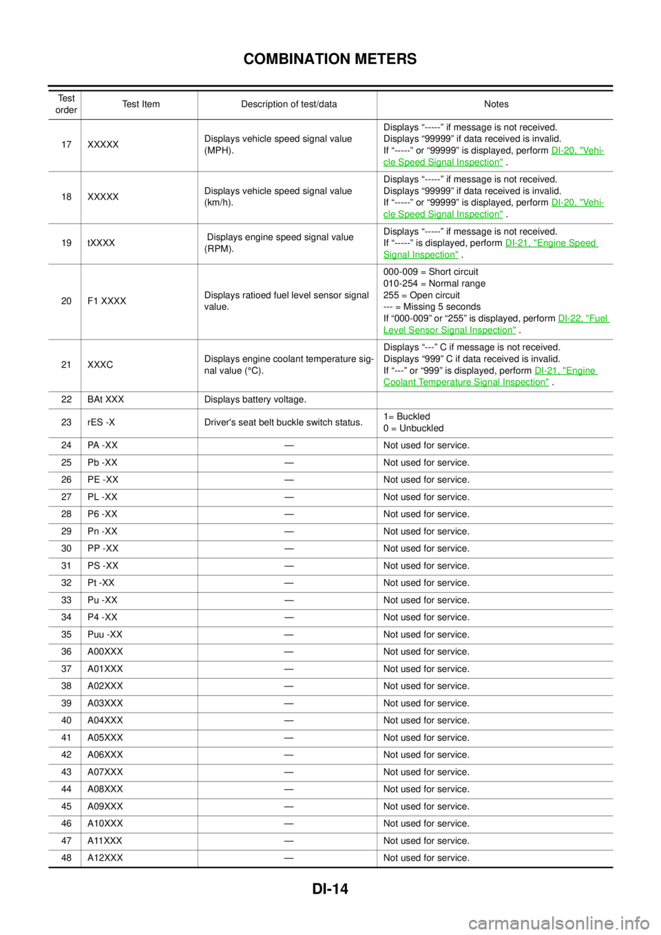
17 XXXXXDisplays vehicle speed signal value
(MPH).Displays “-----” if message is not received.
Displays “99999” if data received is invalid.
If “-----” or “99999” is displayed, performDI-20, "Ve h i-
cle Speed Signal Inspection".
18 XXXXXDisplays vehicle speed signal value
(km/h).Displays “-----” if message is not received.
Displays “99999” if data received is invalid.
If “-----” or “99999” is displayed, performDI-20, "
Ve h i-
cle Speed Signal Inspection".
19 tXXXXDisplays engine speed signal value
(RPM).Displays “-----” if message is not received.
If “-----” is displayed, performDI-21, "
Engine Speed
Signal Inspection".
20 F1 XXXXDisplays ratioed fuel level sensor signal
value.000-009 = Short circuit
010-254 = Normal range
255 = Open circuit
--- = Missing 5 seconds
If “000-009” or “255” is displayed, performDI-22, "
Fuel
Level Sensor Signal Inspection".
21 XXXCDisplays engine coolant temperature sig-
nal value (°C).Displays “---” C if message is not received.
Displays “999” C if data received is invalid.
If “---” or “999” is displayed, performDI-21, "
Engine
Coolant Temperature Signal Inspection".
22 BAt XXX Displays battery voltage.
23 rES -X Driver's seat belt buckle switch status.1= Buckled
0 = Unbuckled
24 PA -XX — Not used for service.
25 Pb -XX — Not used for service.
26 PE -XX — Not used for service.
27 PL -XX — Not used for service.
28 P6 -XX — Not used for service.
29 Pn -XX — Not used for service.
30 PP -XX — Not used for service.
31 PS -XX — Not used for service.
32 Pt -XX — Not used for service.
33 Pu -XX — Not used for service.
34 P4 -XX — Not used for service.
35 Puu -XX — Not used for service.
36 A00XXX — Not used for service.
37 A01XXX — Not used for service.
38 A02XXX — Not used for service.
39 A03XXX — Not used for service.
40 A04XXX — Not used for service.
41 A05XXX — Not used for service.
42 A06XXX — Not used for service.
43 A07XXX — Not used for service.
44 A08XXX — Not used for service.
45 A09XXX — Not used for service.
46 A10XXX — Not used for service.
47 A11XXX — Not used for service.
48 A12XXX — Not used for service. Te s t
orderTest Item Description of test/data Notes
Page 927 of 3171
COMBINATION METERS
DI-17
C
D
E
F
G
H
I
J
L
MA
B
DI
DATA MONITOR
Operation Procedure
1. Touch “DATA MONITOR” on “SELECT DIAG MODE” screen.
2. Touch either “MAIN SIGNALS” or “SELECTION FROM MENU” on the “DATA MONITOR” screen.
3. When “SELECTION FROM MENU” is selected, touch individual items to monitor. When “MAIN SIGNALS”
is selected, main items is monitored.
4. Touch “START”.
5. To record monitored item, touch “RECORD” while monitoring. To
stop recording, touch “STOP”.
Display Item List
MAIN SIGNALS Monitors main signals.
SELECTION FROM MENU Selects and monitors individual signal.
SKIA4957E
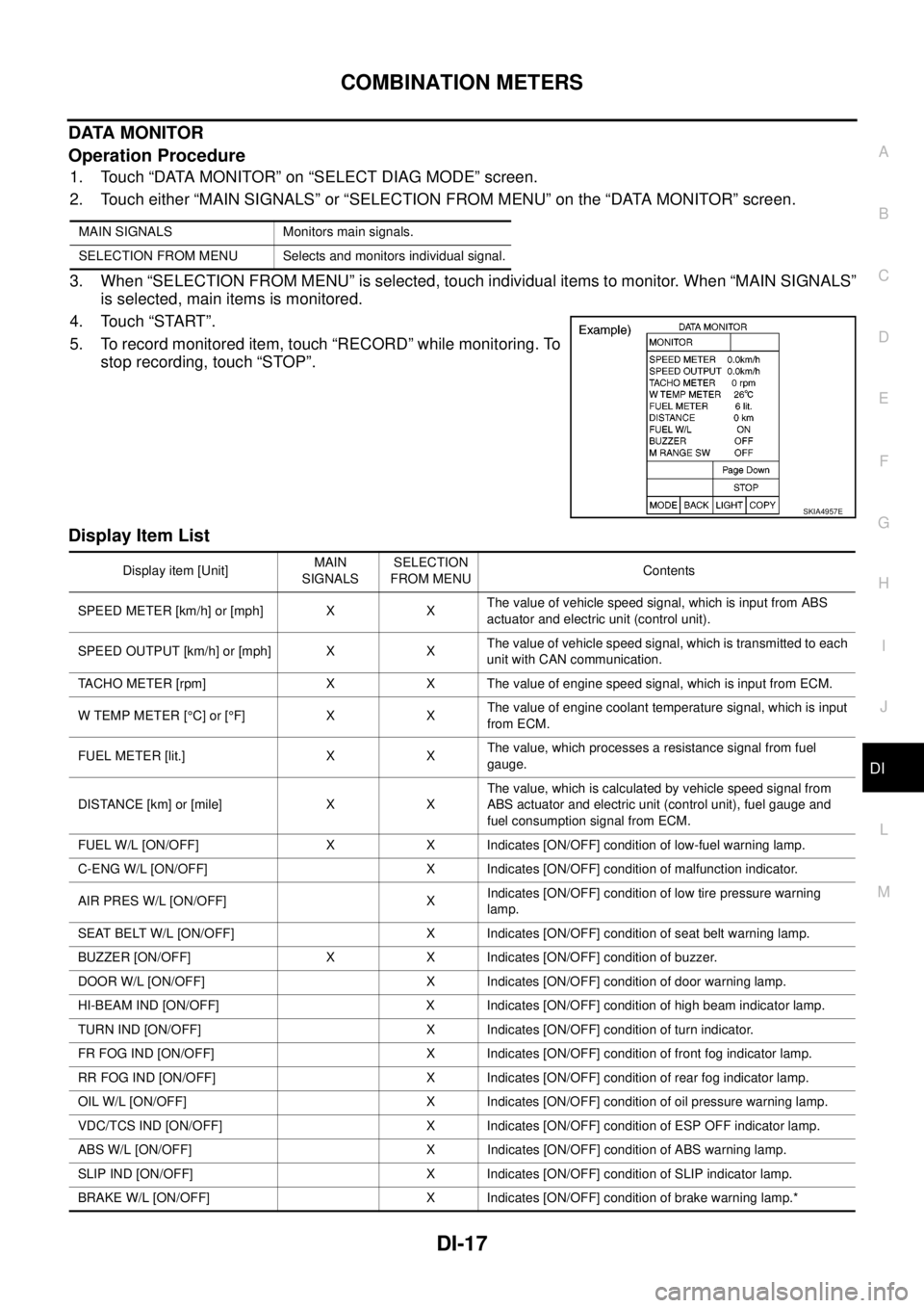
Display item [Unit]MAIN
SIGNALSSELECTION
FROM MENUContents
SPEED METER [km/h] or [mph] X XThe value of vehicle speed signal, which is input from ABS
actuator and electric unit (control unit).
SPEED OUTPUT [km/h] or [mph] X XThe value of vehicle speed signal, which is transmitted to each
unit with CAN communication.
TACHO METER [rpm] X X The value of engine speed signal, which is input from ECM.
W TEMP METER [°C] or [°F] X XThe value of engine coolant temperature signal, which is input
from ECM.
FUEL METER [lit.] X XThe value, which processes a resistance signal from fuel
gauge.
DISTANCE [km] or [mile] X XThe value, which is calculated by vehicle speed signal from
ABS actuator and electric unit (control unit), fuel gauge and
fuel consumption signal from ECM.
FUEL W/L [ON/OFF] X X Indicates [ON/OFF] condition of low-fuel warning lamp.
C-ENG W/L [ON/OFF] X Indicates [ON/OFF] condition of malfunction indicator.
AIR PRES W/L [ON/OFF] XIndicates [ON/OFF] condition of low tire pressure warning
lamp.
SEAT BELT W/L [ON/OFF] X Indicates [ON/OFF] condition of seat belt warning lamp.
BUZZER [ON/OFF] X X Indicates [ON/OFF] condition of buzzer.
DOOR W/L [ON/OFF] X Indicates [ON/OFF] condition of door warning lamp.
HI-BEAM IND [ON/OFF] X Indicates [ON/OFF] condition of high beam indicator lamp.
TURN IND [ON/OFF] X Indicates [ON/OFF] condition of turn indicator.
FR FOG IND [ON/OFF] X Indicates [ON/OFF] condition of front fog indicator lamp.
RR FOG IND [ON/OFF] X Indicates [ON/OFF] condition of rear fog indicator lamp.
OIL W/L [ON/OFF] X Indicates [ON/OFF] condition of oil pressure warning lamp.
VDC/TCS IND [ON/OFF] X Indicates [ON/OFF] condition of ESP OFF indicator lamp.
ABS W/L [ON/OFF] X Indicates [ON/OFF] condition of ABS warning lamp.
SLIP IND [ON/OFF] X Indicates [ON/OFF] condition of SLIP indicator lamp.
BRAKE W/L [ON/OFF] X Indicates [ON/OFF] condition of brake warning lamp.*
Page 929 of 3171
COMBINATION METERS
DI-19
C
D
E
F
G
H
I
J
L
MA
B
DI
PRELIMINARY CHECK
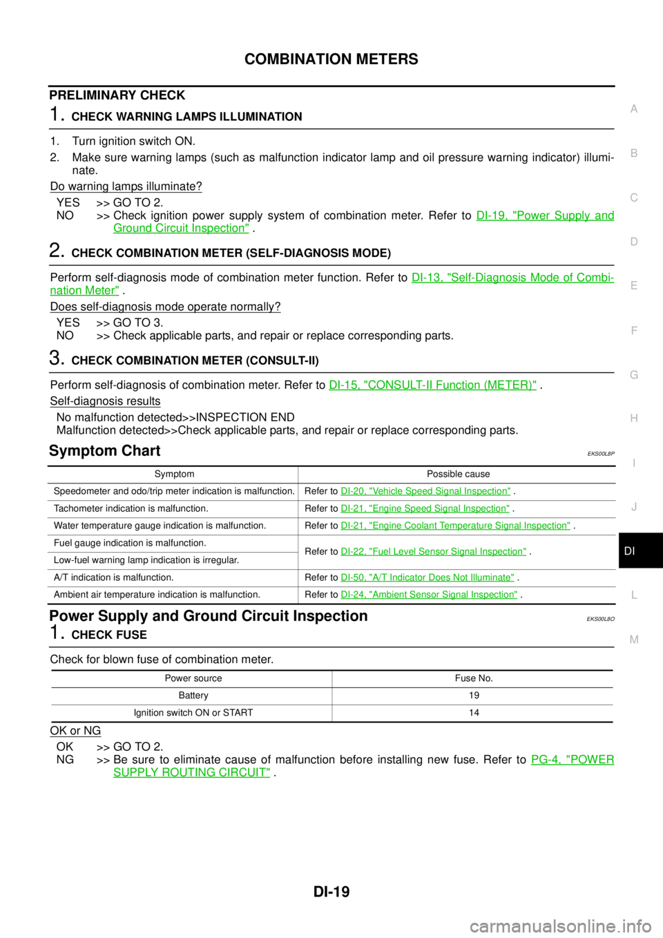
1.CHECK WARNING LAMPS ILLUMINATION
1. Turn ignition switch ON.
2. Make sure warning lamps (such as malfunction indicator lamp and oil pressure warning indicator) illumi-
nate.
Do warning lamps illuminate?
YES >> GO TO 2.
NO >> Check ignition power supply system of combination meter. Refer toDI-19, "
Power Supply and
Ground Circuit Inspection".
2.CHECK COMBINATION METER (SELF-DIAGNOSIS MODE)
Perform self-diagnosis mode of combination meter function. Refer toDI-13, "
Self-Diagnosis Mode of Combi-
nation Meter".
Does self-diagnosis mode operate normally?
YES >> GO TO 3.
NO >> Check applicable parts, and repair or replace corresponding parts.
3.CHECK COMBINATION METER (CONSULT-II)
Perform self-diagnosis of combination meter. Refer toDI-15, "
CONSULT-II Function (METER)".
Self-diagnosis results
No malfunction detected>>INSPECTION END
Malfunction detected>>Check applicable parts, and repair or replace corresponding parts.
Symptom ChartEKS00L8P
Power Supply and Ground Circuit InspectionEKS00L8O
1.CHECK FUSE
Check for blown fuse of combination meter.
OK or NG
OK >> GO TO 2.
NG >> Be sure to eliminate cause of malfunction before installing new fuse. Refer toPG-4, "
POWER
SUPPLY ROUTING CIRCUIT".
Symptom Possible cause
Speedometer and odo/trip meter indication is malfunction. Refer toDI-20, "
Vehicle Speed Signal Inspection".
Tachometer indication is malfunction. Refer toDI-21, "
Engine Speed Signal Inspection".
Water temperature gauge indication is malfunction. Refer toDI-21, "
Engine Coolant Temperature Signal Inspection".
Fuel gauge indication is malfunction.
Refer toDI-22, "
Fuel Level Sensor Signal Inspection".
Low-fuel warning lamp indication is irregular.
A/T indication is malfunction. Refer toDI-50, "
A/T Indicator Does Not Illuminate".
Ambient air temperature indication is malfunction. Refer toDI-24, "
Ambient Sensor Signal Inspection".
Power source Fuse No.
Battery 19
Ignition switch ON or START 14
Page 931 of 3171
COMBINATION METERS
DI-21
C
D
E
F
G
H
I
J
L
MA
B
DI
Engine Speed Signal InspectionEKS00PDG
Symptom: Tachometer indication is malfunction.
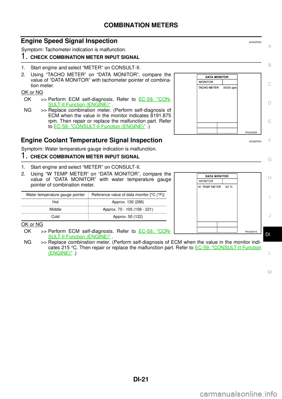
1.CHECK COMBINATION METER INPUT SIGNAL
1. Start engine and select “METER” on CONSULT-II.
2. Using “TACHO METER” on “DATA MONITOR”, compare the
value of “DATA MONITOR” with tachometer pointer of combina-
tion meter.
OK or NG
OK >> Perform ECM self-diagnosis. Refer toEC-59, "CON-
SULT-II Function (ENGINE)".
NG >> Replace combination meter. (Perform self-diagnosis of
ECM when the value in the monitor indicates 8191.875
rpm. Then repair or replace the malfunction part. Refer
toEC-59, "
CONSULT-II Function (ENGINE)".)
Engine Coolant Temperature Signal InspectionEKS00PDH
Symptom: Water temperature gauge indication is malfunction.
1.CHECK COMBINATION METER INPUT SIGNAL
1. Start engine and select “METER” on CONSULT-II.
2. Using “W TEMP METER” on “DATA MONITOR”, compare the
value of “DATA MONITOR” with water temperature gauge
pointer of combination meter.
OK or NG
OK >> Perform ECM self-diagnosis. Refer toEC-59, "CON-
SULT-II Function (ENGINE)".
NG >> Replace combination meter. (Perform self-diagnosis of ECM when the value in the monitor indi-
cates 215°C. Then repair or replace the malfunction part. Refer toEC-59, "
CONSULT-II Function
(ENGINE)".)
PKIA2090E
Water temperature gauge pointer Reference value of data monitor [°C(°F)]
Hot Approx. 130 (266)
Middle Approx. 70 - 105 (158 - 221)
Cold Approx. 50 (122)
PKIA2091E
Page 985 of 3171

EC-5
C
D
E
F
G
H
I
J
K
L
M
ECA . 303
ECM Terminals and Reference Value .................. 303
Wiring Diagram .................................................... 304
Diagnostic Procedure ........................................... 305
Component Inspection ......................................... 307
Removal and Installation ...................................... 308
TC BOOST CONTROL SOLENOID VALVE ........... 309
Description ........................................................... 309
ECM Terminals and Reference Value .................. 310
Wiring Diagram ..................................................... 311
Diagnostic Procedure ........................................... 312
Component Inspection ......................................... 313
Removal and Installation ...................................... 313
INTAKE AIR CONTROL VALVE CONTROL SOLE-
NOID VALVE ........................................................... 314
Description ........................................................... 314
ECM Terminals and Reference Value .................. 314
Wiring Diagram .................................................... 315
Diagnostic Procedure ........................................... 316
Component Inspection ......................................... 318
HEAT UP SWITCH .................................................. 319
Description ........................................................... 319
CONSULT-II Reference Value in Data Monitor Mode
. 319
ECM Terminals and Reference Value .................. 319
Wiring Diagram .................................................... 320
Diagnostic Procedure ........................................... 321
Component Inspection ......................................... 324
REFRIGERANT PRESSURE SENSOR ................. 325
Component Description ........................................ 325
ECM Terminals and Reference Value .................. 325
Wiring Diagram .................................................... 326
Diagnostic Procedure ........................................... 327
Removal and Installation ...................................... 329
BRAKE SWITCH .................................................... 330
Description ........................................................... 330
CONSULT-II Reference Value in Data Monitor Mode.330
ECM Terminals and Reference Value ...................330
Wiring Diagram .....................................................331
Diagnostic Procedure ...........................................332
Component Inspection ..........................................341
PNP SWITCH ..........................................................342
Description ............................................................342
CONSULT-II Reference Value in Data Monitor Mode
.342
ECM Terminals and Reference Value ...................342
Wiring Diagram .....................................................343
Diagnostic Procedure ...........................................344
START SIGNAL ......................................................348
Wiring Diagram .....................................................348
Diagnostic Procedure ...........................................349
ASCD INDICATOR ..................................................351
Component Description ........................................351
Wiring Diagram .....................................................352
Diagnostic Procedure ...........................................353
MI & DATA LINK CONNECTORS ...........................354
Wiring Diagram .....................................................354
AUTOMATIC SPEED CONTROL DEVICE (ASCD). 355
System Description ...............................................355
Component Description ........................................356
SERVICE DATA AND SPECIFICATIONS (SDS) ....357
General Specifications ..........................................357
Mass Air Flow Sensor ...........................................357
Intake Air Temperature Sensor .............................357
Engine Coolant Temperature Sensor ...................357
Fuel Rail Pressure Sensor ....................................357
Fuel Injector ..........................................................357
Glow Plug .............................................................357
EGR Volume Control Valve ..................................357
Crankshaft Position Sensor ..................................357
Camshaft Position Sensor ....................................357
Fuel Pump ............................................................358
Page 994 of 3171
EC-14
PREPARATION
PREPARATION
PFP:00002
Special Service ToolsEBS01KC9
Commercial Service ToolsEBS01KCA
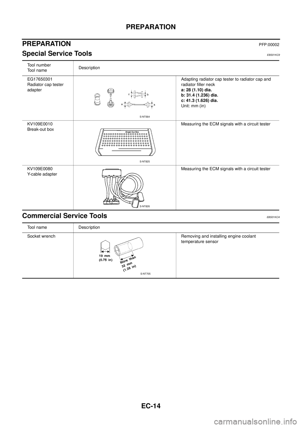
Tool number
Tool nameDescription
EG17650301
Radiator cap tester
adapterAdapting radiator cap tester to radiator cap and
radiator filler neck
a: 28 (1.10) dia.
b: 31.4 (1.236) dia.
c: 41.3 (1.626) dia.
Unit: mm (in)
KV109E0010
Break-out boxMeasuring the ECM signals with a circuit tester
KV109E0080
Y-cable adapterMeasuring the ECM signals with a circuit tester
S-NT564
S-NT825
S-NT826
Tool name Description
Socket wrench Removing and installing engine coolant
temperature sensor
S-NT705