engine coolant NISSAN NAVARA 2005 Repair Repair Manual
[x] Cancel search | Manufacturer: NISSAN, Model Year: 2005, Model line: NAVARA, Model: NISSAN NAVARA 2005Pages: 3171, PDF Size: 49.59 MB
Page 1383 of 3171
EM-1
ENGINE MECHANICAL
B ENGINE
CONTENTS
C
D
E
F
G
H
I
J
K
L
M
SECTIONEM
A
EM
ENGINE MECHANICAL
PRECAUTIONS .......................................................... 4
Precautions for Draining Engine Coolant ................. 4
Precautions for Disconnecting Fuel Piping .............. 4
Precautions for Removal and Disassembly ............. 4
Precautions for Inspection, Repair and Replace-
ment ......................................................................... 4
Precautions for Assembly and Installation ............... 4
Parts Requiring Angle Tightening ............................. 4
Precautions For Liquid Gasket ................................. 5
REMOVAL OF LIQUID GASKET .......................... 5
LIQUID GASKET APPLICATION PROCEDURE..... 5
PREPARATION ........................................................... 6
Special Service Tools ............................................... 6
Commercial Service Tools ........................................ 8
NOISE, VIBRATION AND HARSHNESS (NVH)
TROUBLESHOOTING .............................................. 10
NVH Troubleshooting — Engine Noise .................. 10
Use the Chart Below to Help You Find the Cause
of the Symptom. ...................................................... 11
DRIVE BELTS ........................................................... 12
Checking Drive Belts .............................................. 12
Deflection Adjustment ............................................ 13
POWER STEERING OIL PUMP BELT ............... 13
A/C COMPRESSOR, ALTERNATOR AND
WATER PUMP BELT .......................................... 14
Removal and Installation ........................................ 14
REMOVAL ........................................................... 14
INSTALLATION ................................................... 14
AIR CLEANER AND AIR DUCT ............................... 15
Components ........................................................... 15
Removal and Installation ........................................ 15
REMOVAL ........................................................... 15
INSTALLATION ................................................... 16
CHANGING AIR CLEANER FILTER ................... 17
CHARGE AIR COOLER ........................................... 18
Components ........................................................... 18
Removal and Installation ........................................ 18
REMOVAL ........................................................... 18
INSPECTION AFTER REMOVAL ....................... 19
INSTALLATION ................................................... 19INTAKE MANIFOLD ................................................. 20
Components ........................................................... 20
Removal and Installation ........................................ 21
REMOVAL ........................................................... 21
INSPECTION AFTER REMOVAL ....................... 22
INSTALLATION ................................................... 22
INSPECTION AFTER INSTALLATION ................ 25
CATALYST ................................................................ 26
Components ........................................................... 26
Removal and Installation ........................................ 26
REMOVAL ........................................................... 26
INSTALLATION ................................................... 27
TURBO CHARGER ................................................... 28
Components ........................................................... 28
Removal and Installation ........................................ 29
REMOVAL ........................................................... 29
INSPECTION AFTER REMOVAL ....................... 30
TROUBLE DIAGNOSIS OF TURBOCHARGER... 32
INSTALLATION ................................................... 33
EXHAUST MANIFOLD ............................................. 34
Components ........................................................... 34
Removal and Installation ........................................ 34
REMOVAL ........................................................... 34
INSPECTION AFTER REMOVAL ....................... 35
INSTALLATION ................................................... 35
INSPECTION AFTER INSTALLATION ................ 35
OIL PAN AND OIL STRAINER ................................. 36
Components ........................................................... 36
Removal and Installation ........................................ 36
REMOVAL ........................................................... 36
INSPECTION AFTER REMOVAL ....................... 38
INSTALLATION ................................................... 38
INSPECTION AFTER INSTALLATION ................ 40
GLOW PLUG ............................................................ 41
Components ........................................................... 41
Removal and Installation ........................................ 41
REMOVAL ........................................................... 41
INSTALLATION ................................................... 41
VACUUM PUMP ........................................................ 42
Page 1386 of 3171
EM-4
PRECAUTIONS
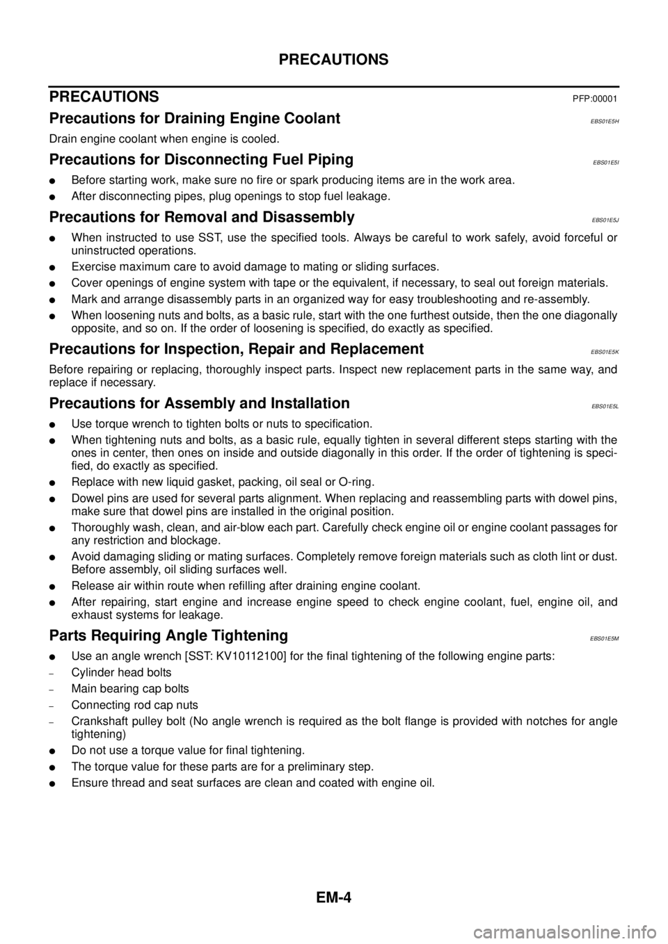
PRECAUTIONS
PFP:00001
Precautions for Draining Engine CoolantEBS01E5H
Drain engine coolant when engine is cooled.
Precautions for Disconnecting Fuel PipingEBS01E5I
lBefore starting work, make sure no fire or spark producing items are in the work area.
lAfter disconnecting pipes, plug openings to stop fuel leakage.
Precautions for Removal and DisassemblyEBS01E5J
lWhen instructed to use SST, use the specified tools. Always be careful to work safely, avoid forceful or
uninstructed operations.
lExercise maximum care to avoid damage to mating or sliding surfaces.
lCover openings of engine system with tape or the equivalent, if necessary, to seal out foreign materials.
lMark and arrange disassembly parts in an organized way for easy troubleshooting and re-assembly.
lWhen loosening nuts and bolts, as a basic rule, start with the one furthest outside, then the one diagonally
opposite, and so on. If the order of loosening is specified, do exactly as specified.
Precautions for Inspection, Repair and ReplacementEBS01E5K
Before repairing or replacing, thoroughly inspect parts. Inspect new replacement parts in the same way, and
replace if necessary.
Precautions for Assembly and InstallationEBS01E5L
lUsetorquewrenchtotightenboltsornutstospecification.
lWhen tightening nuts and bolts, as a basic rule, equally tighten in several different steps starting with the
ones in center, then ones on inside and outside diagonally in this order. If the order of tightening is speci-
fied, do exactly as specified.
lReplace with new liquid gasket, packing, oil seal or O-ring.
lDowel pins are used for several parts alignment. When replacing and reassembling parts with dowel pins,
make sure that dowel pins are installed in the original position.
lThoroughly wash, clean, and air-blow each part. Carefully check engine oil or engine coolant passages for
any restriction and blockage.
lAvoid damaging sliding or mating surfaces. Completely remove foreign materials such as cloth lint or dust.
Before assembly, oil sliding surfaces well.
lRelease air within route when refilling after draining engine coolant.
lAfter repairing, start engine and increase engine speed to check engine coolant, fuel, engine oil, and
exhaust systems for leakage.
Parts Requiring Angle TighteningEBS01E5M
lUse an angle wrench [SST: KV10112100] for the final tightening of the following engine parts:
–Cylinder head bolts
–Main bearing cap bolts
–Connecting rod cap nuts
–Crankshaft pulley bolt (No angle wrench is required as the bolt flange is provided with notches for angle
tightening)
lDo not use a torque value for final tightening.
lThe torque value for these parts are for a preliminary step.
lEnsure thread and seat surfaces are clean and coated with engine oil.
Page 1387 of 3171
PRECAUTIONS
EM-5
C
D
E
F
G
H
I
J
K
L
MA
EM
Precautions For Liquid GasketEBS01E5N
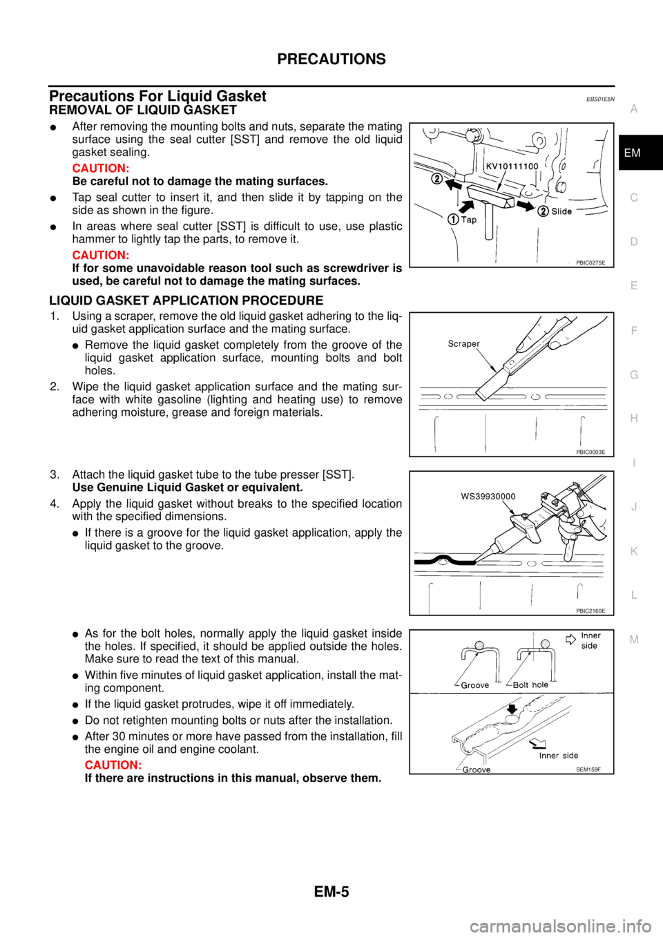
REMOVAL OF LIQUID GASKET
lAfter removing the mounting bolts and nuts, separate the mating
surface using the seal cutter [SST] and remove the old liquid
gasket sealing.
CAUTION:
Be careful not to damage the mating surfaces.
lTap seal cutter to insert it, and then slide it by tapping on the
side as shown in the figure.
lIn areas where seal cutter [SST] is difficult to use, use plastic
hammer to lightly tap the parts, to remove it.
CAUTION:
If for some unavoidable reason tool such as screwdriver is
used, be careful not to damage the mating surfaces.
LIQUID GASKET APPLICATION PROCEDURE
1. Using a scraper, remove the old liquid gasket adhering to the liq-
uid gasket application surface and the mating surface.
lRemove the liquid gasket completely from the groove of the
liquid gasket application surface, mounting bolts and bolt
holes.
2. Wipe the liquid gasket application surface and the mating sur-
face with white gasoline (lighting and heating use) to remove
adhering moisture, grease and foreign materials.
3. Attach the liquid gasket tube to the tube presser [SST].
Use Genuine Liquid Gasket or equivalent.
4. Apply the liquid gasket without breaks to the specified location
with the specified dimensions.
lIf there is a groove for the liquid gasket application, apply the
liquid gasket to the groove.
lAs for the bolt holes, normally apply the liquid gasket inside
the holes. If specified, it should be applied outside the holes.
Make sure to read the text of this manual.
lWithin five minutes of liquid gasket application, install the mat-
ing component.
lIf the liquid gasket protrudes, wipe it off immediately.
lDo not retighten mounting bolts or nuts after the installation.
lAfter 30 minutes or more have passed from the installation, fill
the engine oil and engine coolant.
CAUTION:
If there are instructions in this manual, observe them.
PBIC0275E
PBIC0003E
PBIC2160E
SEM159F
Page 1395 of 3171
DRIVE BELTS
EM-13
C
D
E
F
G
H
I
J
K
L
MA
EM
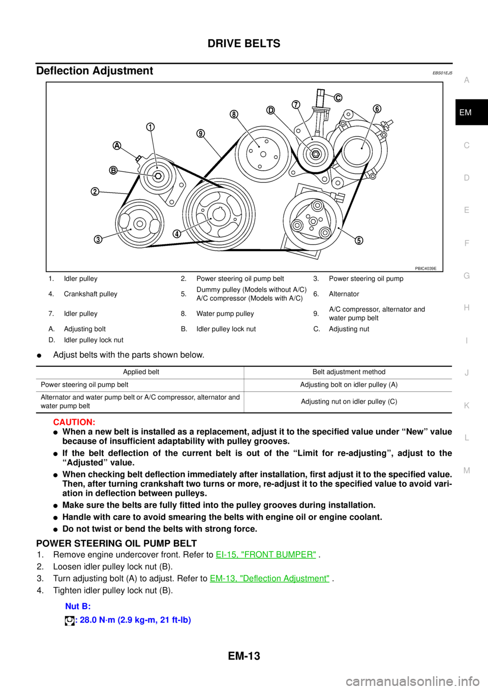
Deflection AdjustmentEBS01EJ5
lAdjust belts with the parts shown below.
CAUTION:
lWhen a new belt is installed as a replacement, adjust it to the specified value under “New” value
because of insufficient adaptability with pulley grooves.
lIf the belt deflection of the current belt is out of the “Limit for re-adjusting”, adjust to the
“Adjusted” value.
lWhen checking belt deflection immediately after installation, first adjust it to the specified value.
Then, after turning crankshaft two turns or more, re-adjust it to the specified value to avoid vari-
ation in deflection between pulleys.
lMake sure the belts are fully fitted into the pulley grooves during installation.
lHandle with care to avoid smearing the belts with engine oil or engine coolant.
lDo not twist or bend the belts with strong force.
POWER STEERING OIL PUMP BELT
1. Remove engine undercover front. Refer toEI-15, "FRONT BUMPER".
2. Loosen idler pulley lock nut (B).
3. Turn adjusting bolt (A) to adjust. Refer toEM-13, "
Deflection Adjustment".
4. Tighten idler pulley lock nut (B).
1. Idler pulley 2. Power steering oil pump belt 3. Power steering oil pump
4. Crankshaft pulley 5.Dummy pulley (Models without A/C)
A/C compressor (Models with A/C)6. Alternator
7. Idler pulley 8. Water pump pulley 9.A/C compressor, alternator and
water pump belt
A. Adjusting bolt B. Idler pulley lock nut C. Adjusting nut
D. Idler pulley lock nut
PBIC4039E
Applied belt Belt adjustment method
Power steering oil pump belt Adjusting bolt on idler pulley (A)
Alternator and water pump belt or A/C compressor, alternator and
water pump beltAdjusting nut on idler pulley (C)
Nut B:
: 28.0 N·m (2.9 kg-m, 21 ft-lb)
Page 1403 of 3171
INTAKE MANIFOLD
EM-21
C
D
E
F
G
H
I
J
K
L
MA
EM
lRefer toGI-10, "Components"for symbol marks except in the above.
Removal and InstallationEBS01EJF
REMOVAL
WARNING:
To avoid the danger of being scalded, do not drain engine coolant when engine is hot.
1. Drain engine coolant. Refer toCO-7, "
Changing Engine Coolant".
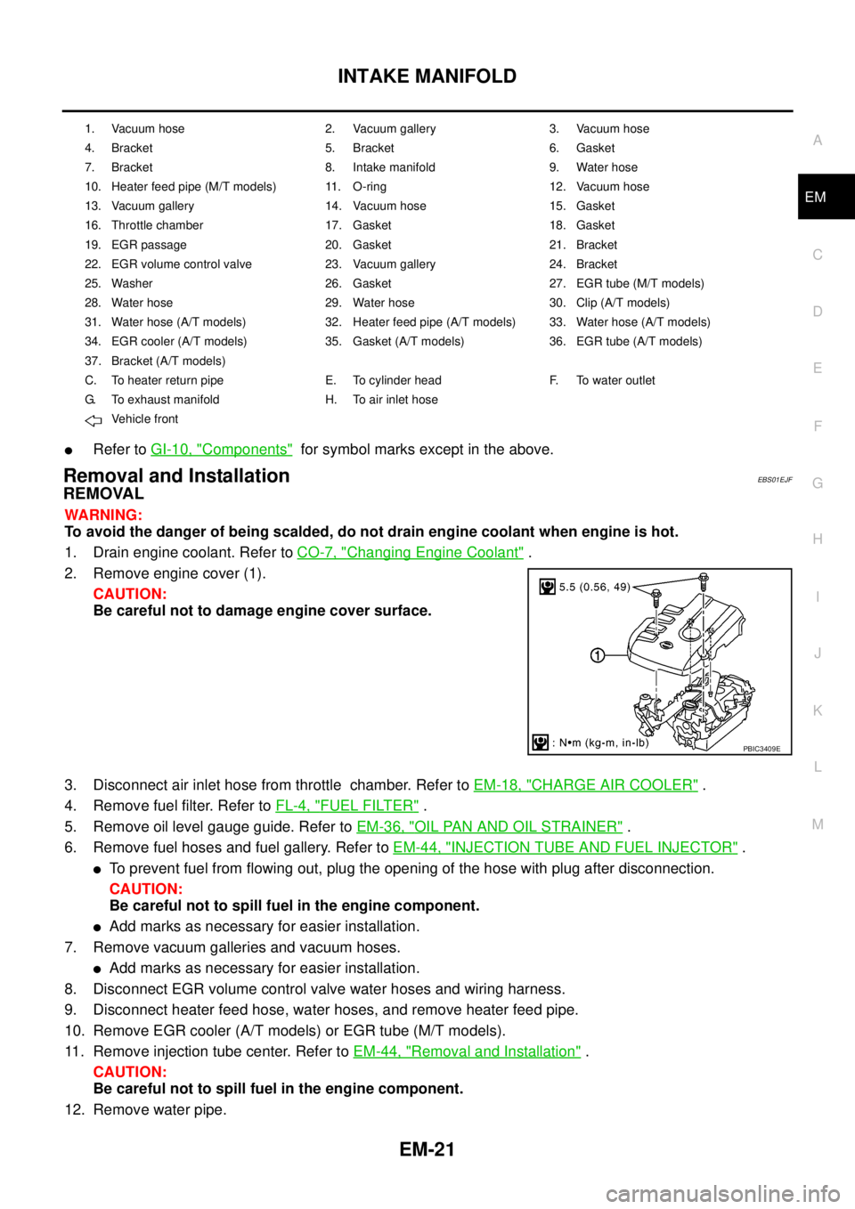
2. Remove engine cover (1).
CAUTION:
Be careful not to damage engine cover surface.
3. Disconnect air inlet hose from throttle chamber. Refer toEM-18, "
CHARGE AIR COOLER".
4. Remove fuel filter. Refer toFL-4, "
FUEL FILTER".
5. Remove oil level gauge guide. Refer toEM-36, "
OIL PAN AND OIL STRAINER".
6. Remove fuel hoses and fuel gallery. Refer toEM-44, "
INJECTION TUBE AND FUEL INJECTOR".
lTo prevent fuel from flowing out, plug the opening of the hose with plug after disconnection.
CAUTION:
Be careful not to spill fuel in the engine component.
lAdd marks as necessary for easier installation.
7. Remove vacuum galleries and vacuum hoses.
lAdd marks as necessary for easier installation.
8. Disconnect EGR volume control valve water hoses and wiring harness.
9. Disconnect heater feed hose, water hoses, and remove heater feed pipe.
10. Remove EGR cooler (A/T models) or EGR tube (M/T models).
11. Remove injection tube center. Refer toEM-44, "
Removal and Installation".
CAUTION:
Be careful not to spill fuel in the engine component.
12. Remove water pipe.
1. Vacuum hose 2. Vacuum gallery 3. Vacuum hose
4. Bracket 5. Bracket 6. Gasket
7. Bracket 8. Intake manifold 9. Water hose
10. Heater feed pipe (M/T models) 11. O-ring 12. Vacuum hose
13. Vacuum gallery 14. Vacuum hose 15. Gasket
16. Throttle chamber 17. Gasket 18. Gasket
19. EGR passage 20. Gasket 21. Bracket
22. EGR volume control valve 23. Vacuum gallery 24. Bracket
25. Washer 26. Gasket 27. EGR tube (M/T models)
28. Water hose 29. Water hose 30. Clip (A/T models)
31. Water hose (A/T models) 32. Heater feed pipe (A/T models) 33. Water hose (A/T models)
34. EGR cooler (A/T models) 35. Gasket (A/T models) 36. EGR tube (A/T models)
37. Bracket (A/T models)
C. To heater return pipe E. To cylinder head F. To water outlet
G. To exhaust manifold H. To air inlet hose
Vehicle front
PBIC3409E
Page 1411 of 3171
TURBO CHARGER
EM-29
C
D
E
F
G
H
I
J
K
L
MA
EM
lRefer toGI-10, "Components"for symbol marks in the figure.
Removal and InstallationEBS01E5X
REMOVAL
lAfter applying penetrative lubricant to the mounting nuts, check for the penetration of the lubricant, and
then loosen the nuts to remove.
1. Drain engine coolant (4WD models). Refer toCO-7, "
Changing Engine Coolant".
2. Remove air inlet hose and air inlet pipe. Refer toEM-18, "
CHARGE AIR COOLER".
3. Remove air duct and air inlet pipes. Refer toEM-15, "
AIR CLEANER AND AIR DUCT".
4. Remove exhaust manifold cover. Refer toEM-34, "
EXHAUST MANIFOLD".
5. Remove exhaust outlet and catalyst. Refer toEM-26, "
CATALYST".
6. Remove eye bolt and water hose from water tube (4WD models).
7. Loosen and remove eye-bolts from oil feed tube.
8. Disconnect oil return hose from oil return tube.
9. Remove turbocharger with water tube (4WD models) and oil feed tube and oil return tube.
CAUTION:
Be careful not to deform water tube and oil feed tube and oil return tube.
10. Remove water tube (4WD models) and oil feed tube and oil return tube from turbocharger.
CAUTION:
lDo not disassemble or adjust the turbocharger.
lBe careful not to contact with the vehicle.
lDo not hold turbocharger boost control actuator and actuator rod.
Water Tube and Oil Tube
lClean inside of water tube (4WD models), oil feed tube and oil return tube, and check tubes for clogging.
lReplace water tube (4WD models), oil feed tube and/or oil return tube if clogging still exists after cleaning.
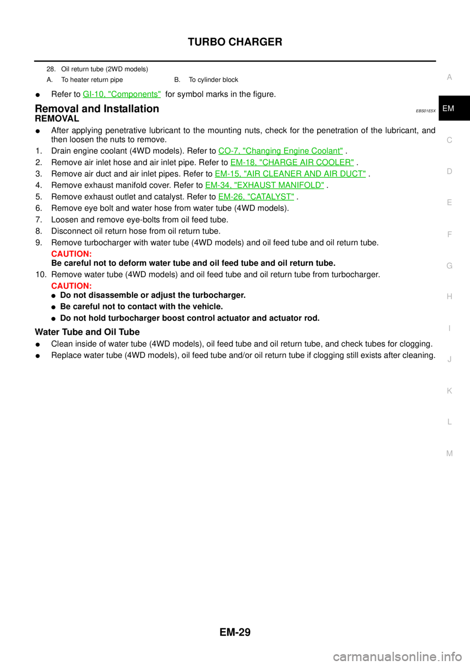
28. Oil return tube (2WD models)
A. To heater return pipe B. To cylinder block
Page 1412 of 3171
EM-30
TURBO CHARGER
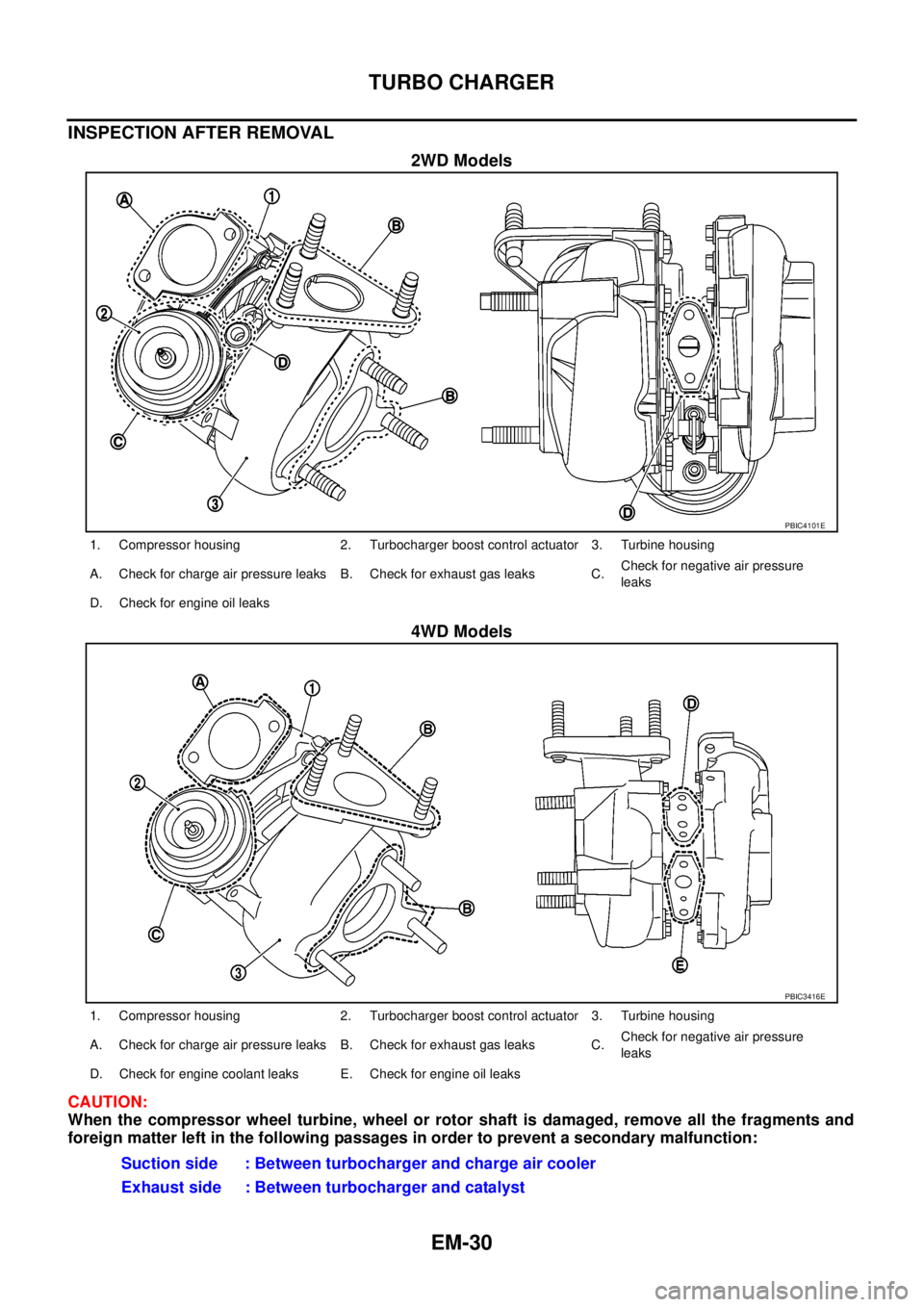
INSPECTION AFTER REMOVAL
2WD Models
4WD Models
CAUTION:
When the compressor wheel turbine, wheel or rotor shaft is damaged, remove all the fragments and
foreign matter left in the following passages in order to prevent a secondary malfunction:
PBIC4101E
1. Compressor housing 2. Turbocharger boost control actuator 3. Turbine housing
A. Check for charge air pressure leaks B. Check for exhaust gas leaks C.Check for negative air pressure
leaks
D. Check for engine oil leaks
PBIC3416E
1. Compressor housing 2. Turbocharger boost control actuator 3. Turbine housing
A. Check for charge air pressure leaks B. Check for exhaust gas leaks C.Check for negative air pressure
leaks
D. Check for engine coolant leaks E. Check for engine oil leaks
Suction side : Between turbocharger and charge air cooler
Exhaust side : Between turbocharger and catalyst
Page 1416 of 3171
EM-34
EXHAUST MANIFOLD
EXHAUST MANIFOLD
PFP:14004
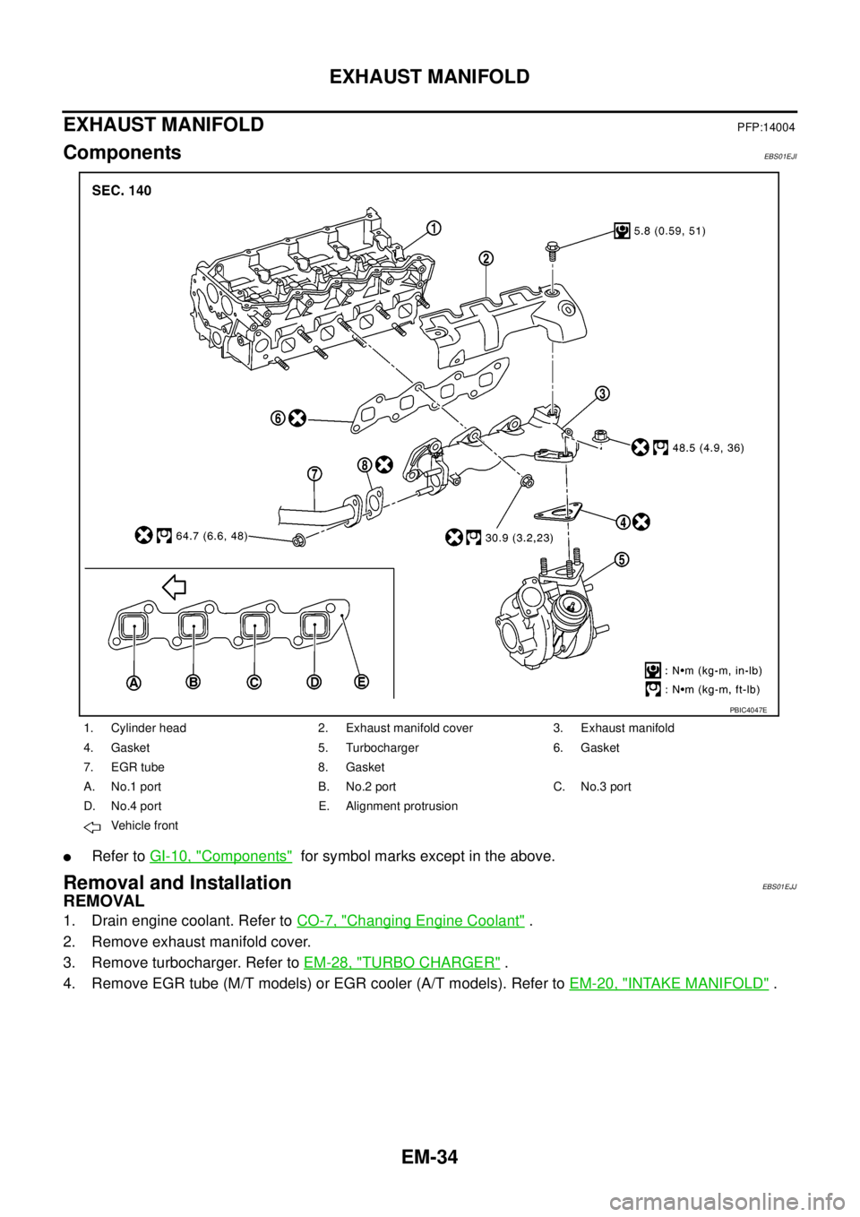
ComponentsEBS01EJI
lRefer toGI-10, "Components"for symbol marks except in the above.
Removal and InstallationEBS01EJJ
REMOVAL
1. Drain engine coolant. Refer toCO-7, "Changing Engine Coolant".
2. Remove exhaust manifold cover.
3. Remove turbocharger. Refer toEM-28, "
TURBO CHARGER".
4. Remove EGR tube (M/T models) or EGR cooler (A/T models). Refer toEM-20, "
INTAKE MANIFOLD".
1. Cylinder head 2. Exhaust manifold cover 3. Exhaust manifold
4. Gasket 5. Turbocharger 6. Gasket
7. EGR tube 8. Gasket
A. No.1 port B. No.2 port C. No.3 port
D. No.4 port E. Alignment protrusion
Vehicle front
PBIC4047E
Page 1441 of 3171
CAMSHAFT
EM-59
C
D
E
F
G
H
I
J
K
L
MA
EM
CAMSHAFTPFP:13001
ComponentsEBS01EK5
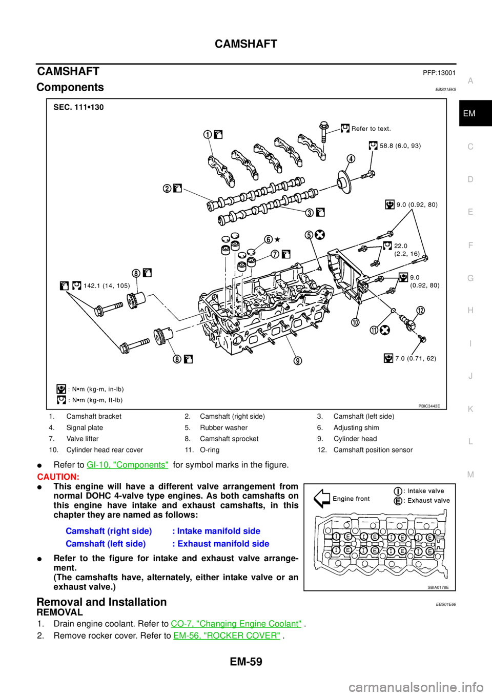
lRefer toGI-10, "Components"for symbol marks in the figure.
CAUTION:
lThis engine will have a different valve arrangement from
normal DOHC 4-valve type engines. As both camshafts on
this engine have intake and exhaust camshafts, in this
chapter they are named as follows:
lRefer to the figure for intake and exhaust valve arrange-
ment.
(The camshafts have, alternately, either intake valve or an
exhaust valve.)
Removal and InstallationEBS01E66
REMOVAL
1. Drain engine coolant. Refer toCO-7, "Changing Engine Coolant".
2. Remove rocker cover. Refer toEM-56, "
ROCKER COVER".
1. Camshaft bracket 2. Camshaft (right side) 3. Camshaft (left side)
4. Signal plate 5. Rubber washer 6. Adjusting shim
7. Valve lifter 8. Camshaft sprocket 9. Cylinder head
10. Cylinder head rear cover 11. O-ring 12. Camshaft position sensor
Camshaft (right side) : Intake manifold side
Camshaft (left side) : Exhaust manifold side
PBIC3443E
SBIA0178E
Page 1447 of 3171
CAMSHAFT
EM-65
C
D
E
F
G
H
I
J
K
L
MA
EM
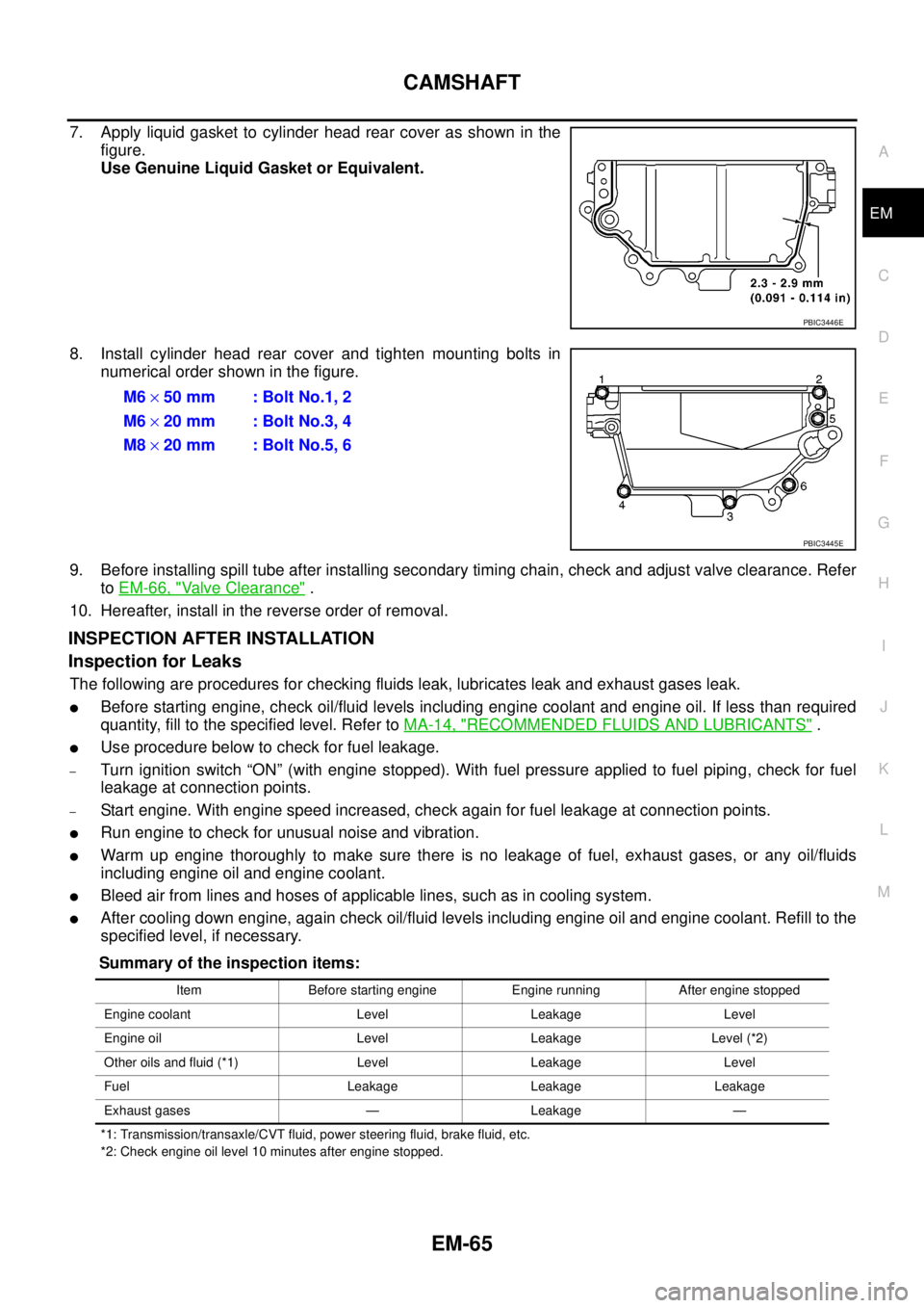
7. Apply liquid gasket to cylinder head rear cover as shown in the
figure.
Use Genuine Liquid Gasket or Equivalent.
8. Install cylinder head rear cover and tighten mounting bolts in
numerical order shown in the figure.
9. Before installing spill tube after installing secondary timing chain, check and adjust valve clearance. Refer
toEM-66, "
Valve Clearance".
10. Hereafter, install in the reverse order of removal.
INSPECTION AFTER INSTALLATION
Inspection for Leaks
The following are procedures for checking fluids leak, lubricates leak and exhaust gases leak.
lBefore starting engine, check oil/fluid levels including engine coolant and engine oil. If less than required
quantity, fill to the specified level. Refer toMA-14, "
RECOMMENDED FLUIDS AND LUBRICANTS".
lUse procedure below to check for fuel leakage.
–Turn ignition switch “ON” (with engine stopped). With fuel pressure applied to fuel piping, check for fuel
leakage at connection points.
–Start engine. With engine speed increased, check again for fuel leakage at connection points.
lRun engine to check for unusual noise and vibration.
lWarm up engine thoroughly to make sure there is no leakage of fuel, exhaust gases, or any oil/fluids
including engine oil and engine coolant.
lBleed air from lines and hoses of applicable lines, such as in cooling system.
lAfter cooling down engine, again check oil/fluid levels including engine oil and engine coolant. Refill to the
specified level, if necessary.
Summary of the inspection items:
*1: Transmission/transaxle/CVT fluid, power steering fluid, brake fluid, etc.
*2: Check engine oil level 10 minutes after engine stopped.
PBIC3446E
M6´50 mm : Bolt No.1, 2
M6´20 mm : Bolt No.3, 4
M8´20 mm : Bolt No.5, 6
PBIC3445E
Item Before starting engine Engine running After engine stopped
Engine coolant Level Leakage Level
Engine oil Level Leakage Level (*2)
Other oils and fluid (*1) Level Leakage Level
Fuel Leakage Leakage Leakage
Exhaust gases — Leakage —