NISSAN NAVARA 2005 Repair Workshop Manual
Manufacturer: NISSAN, Model Year: 2005, Model line: NAVARA, Model: NISSAN NAVARA 2005Pages: 3171, PDF Size: 49.59 MB
Page 401 of 3171
TROUBLE DIAGNOSIS
ATC-67
C
D
E
F
G
H
I
K
L
MA
B
AT C
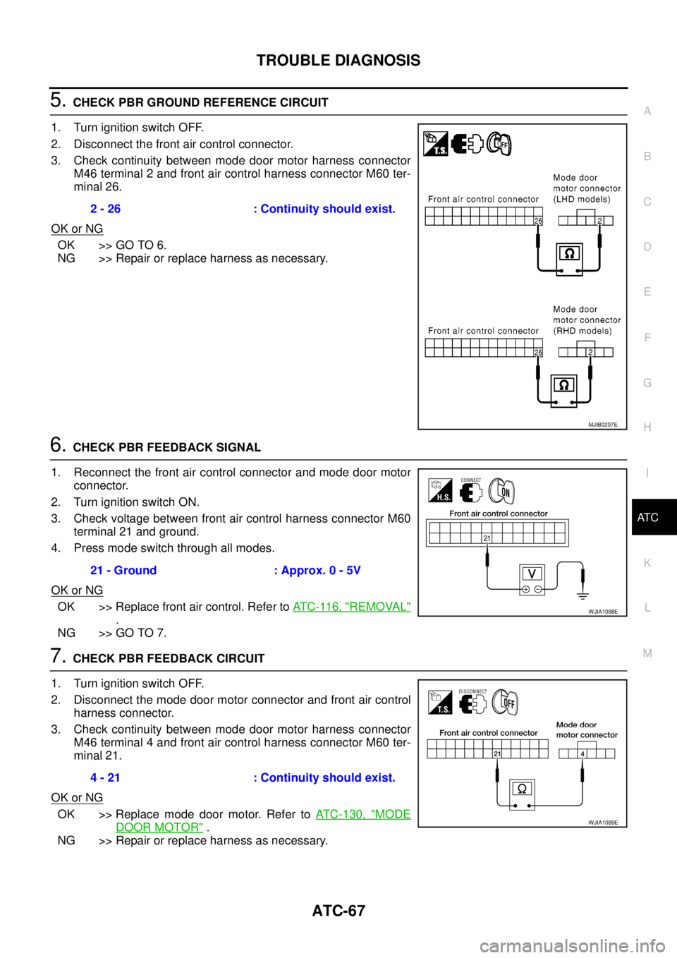
5.CHECK PBR GROUND REFERENCE CIRCUIT
1. Turn ignition switch OFF.
2. Disconnect the front air control connector.
3. Check continuity between mode door motor harness connector
M46 terminal 2 and front air control harness connector M60 ter-
minal 26.
OK or NG
OK >> GO TO 6.
NG >> Repair or replace harness as necessary.
6.CHECK PBR FEEDBACK SIGNAL
1. Reconnect the front air control connector and mode door motor
connector.
2. Turn ignition switch ON.
3. Check voltage between front air control harness connector M60
terminal 21 and ground.
4. Press mode switch through all modes.
OK or NG
OK >> Replace front air control. Refer toAT C - 11 6 , "REMOVAL"
.
NG >> GO TO 7.
7.CHECK PBR FEEDBACK CIRCUIT
1. Turn ignition switch OFF.
2. Disconnect the mode door motor connector and front air control
harness connector.
3. Check continuity between mode door motor harness connector
M46 terminal 4 and front air control harness connector M60 ter-
minal 21.
OK or NG
OK >> Replace mode door motor. Refer toATC-130, "MODE
DOOR MOTOR".
NG >> Repair or replace harness as necessary.2 - 26 : Continuity should exist.
MJIB0207E
21 - Ground : Approx. 0 - 5V
WJIA1088E
4 - 21 : Continuity should exist.
WJIA1089E
Page 402 of 3171
ATC-68
TROUBLE DIAGNOSIS
Air Mix Door Motor Circuit
EJS006BL
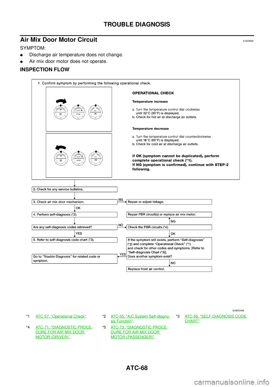
SYMPTOM:
lDischarge air temperature does not change.
lAir mix door motor does not operate.
INSPECTION FLOW
*1AT C - 5 7 , "Operational Check".*2AT C - 5 5 , "A/C System Self-diagno-
sis Function".*3AT C - 5 6 , "
SELF-DIAGNOSIS CODE
CHART".
*4AT C - 7 1 , "
DIAGNOSTIC PROCE-
DURE FOR AIR MIX DOOR
MOTOR (DRIVER)".*5AT C - 7 3 , "
DIAGNOSTIC PROCE-
DURE FOR AIR MIX DOOR
MOTOR (PASSENGER)".
MJIB0346E
Page 403 of 3171
TROUBLE DIAGNOSIS
ATC-69
C
D
E
F
G
H
I
K
L
MA
B
AT C
SYSTEM DESCRIPTION
Component Parts
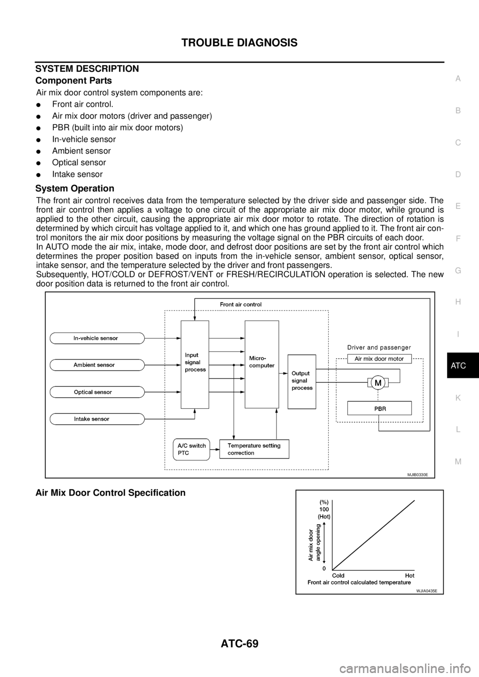
Air mix door control system components are:
lFront air control.
lAir mix door motors (driver and passenger)
lPBR (built into air mix door motors)
lIn-vehicle sensor
lAmbient sensor
lOptical sensor
lIntake sensor
System Operation
The front air control receives data from the temperature selected by the driver side and passenger side. The
front air control then applies a voltage to one circuit of the appropriate air mix door motor, while ground is
applied to the other circuit, causing the appropriate air mix door motor to rotate. The direction of rotation is
determined by which circuit has voltage applied to it, and which one has ground applied to it. The front air con-
trol monitors the air mix door positions by measuring the voltage signal on the PBR circuits of each door.
In AUTO mode the air mix, intake, mode door, and defrost door positions are set by the front air control which
determines the proper position based on inputs from the in-vehicle sensor, ambient sensor, optical sensor,
intake sensor, and the temperature selected by the driver and front passengers.
Subsequently, HOT/COLD or DEFROST/VENT or FRESH/RECIRCULATION operation is selected. The new
door position data is returned to the front air control.
Air Mix Door Control Specification
MJIB0330E
WJIA0435E
Page 404 of 3171
ATC-70
TROUBLE DIAGNOSIS
COMPONENT DESCRIPTION
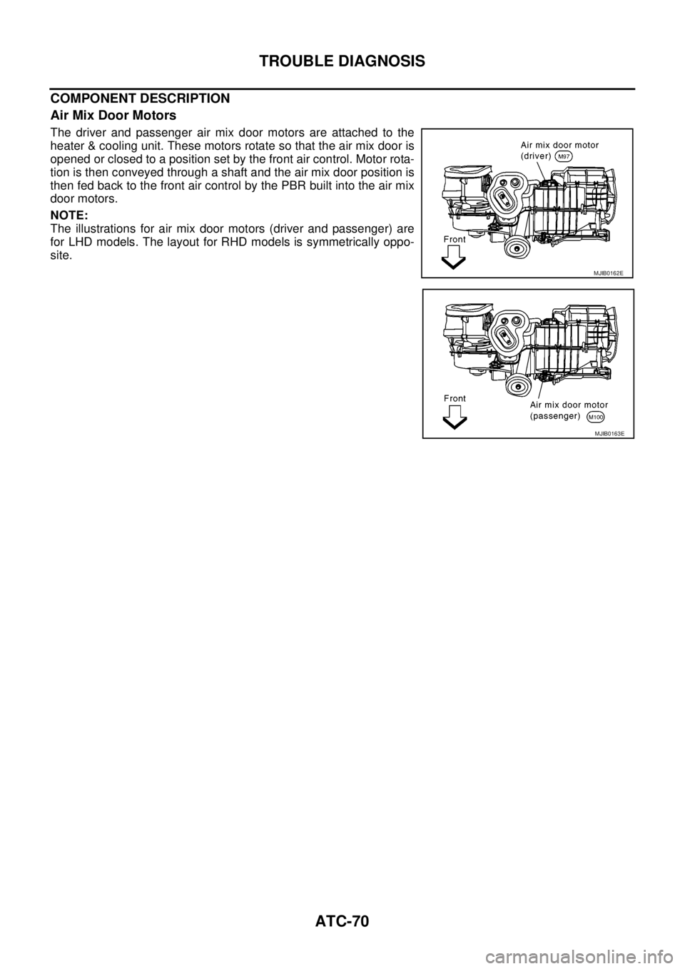
Air Mix Door Motors
The driver and passenger air mix door motors are attached to the
heater & cooling unit. These motors rotate so that the air mix door is
opened or closed to a position set by the front air control. Motor rota-
tion is then conveyed through a shaft and the air mix door position is
then fed back to the front air control by the PBR built into the air mix
door motors.
NOTE:
The illustrations for air mix door motors (driver and passenger) are
for LHD models. The layout for RHD models is symmetrically oppo-
site.
MJIB0162E
MJIB0163E
Page 405 of 3171
TROUBLE DIAGNOSIS
ATC-71
C
D
E
F
G
H
I
K
L
MA
B
AT C
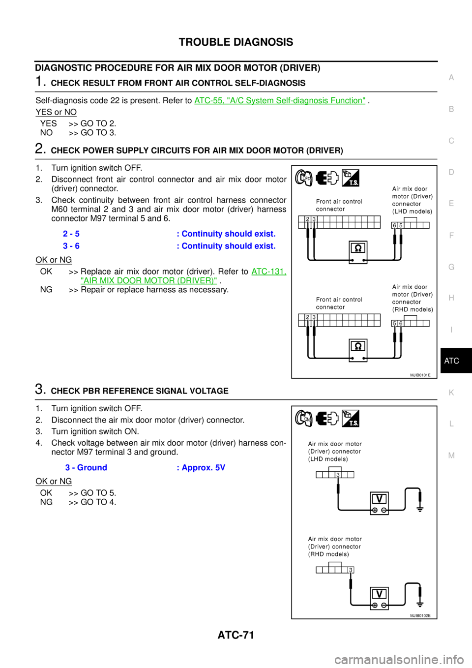
DIAGNOSTIC PROCEDURE FOR AIR MIX DOOR MOTOR (DRIVER)
1.CHECK RESULT FROM FRONT AIR CONTROL SELF-DIAGNOSIS
Self-diagnosis code 22 is present. Refer toAT C - 5 5 , "
A/C System Self-diagnosis Function".
YES or NO
YES >> GO TO 2.
NO >> GO TO 3.
2.CHECK POWER SUPPLY CIRCUITS FOR AIR MIX DOOR MOTOR (DRIVER)
1. Turn ignition switch OFF.
2. Disconnect front air control connector and air mix door motor
(driver) connector.
3. Check continuity between front air control harness connector
M60 terminal 2 and 3 and air mix door motor (driver) harness
connector M97 terminal 5 and 6.
OK or NG
OK >> Replace air mix door motor (driver). Refer toATC-131,
"AIR MIX DOOR MOTOR (DRIVER)".
NG >> Repair or replace harness as necessary.
3.CHECK PBR REFERENCE SIGNAL VOLTAGE
1. Turn ignition switch OFF.
2. Disconnect the air mix door motor (driver) connector.
3. Turn ignition switch ON.
4. Check voltage between air mix door motor (driver) harness con-
nector M97 terminal 3 and ground.
OK or NG
OK >> GO TO 5.
NG >> GO TO 4.2 - 5 : Continuity should exist.
3 - 6 : Continuity should exist.
MJIB0101E
3 - Ground : Approx. 5V
MJIB0102E
Page 406 of 3171
ATC-72
TROUBLE DIAGNOSIS
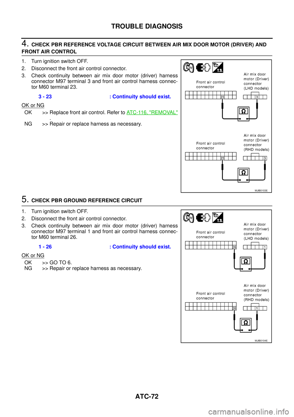
4.CHECK PBR REFERENCE VOLTAGE CIRCUIT BETWEEN AIR MIX DOOR MOTOR (DRIVER) AND
FRONT AIR CONTROL
1. Turn ignition switch OFF.
2. Disconnect the front air control connector.
3. Check continuity between air mix door motor (driver) harness
connector M97 terminal 3 and front air control harness connec-
tor M60 terminal 23.
OK or NG
OK >> Replace front air control. Refer toAT C - 11 6 , "REMOVAL"
.
NG >> Repair or replace harness as necessary.
5.CHECK PBR GROUND REFERENCE CIRCUIT
1. Turn ignition switch OFF.
2. Disconnect the front air control connector.
3. Check continuity between air mix door motor (driver) harness
connector M97 terminal 1 and front air control harness connec-
tor M60 terminal 26.
OK or NG
OK >> GO TO 6.
NG >> Repair or replace harness as necessary.3 - 23 : Continuity should exist.
MJIB0103E
1 - 26 : Continuity should exist.
MJIB0104E
Page 407 of 3171
TROUBLE DIAGNOSIS
ATC-73
C
D
E
F
G
H
I
K
L
MA
B
AT C
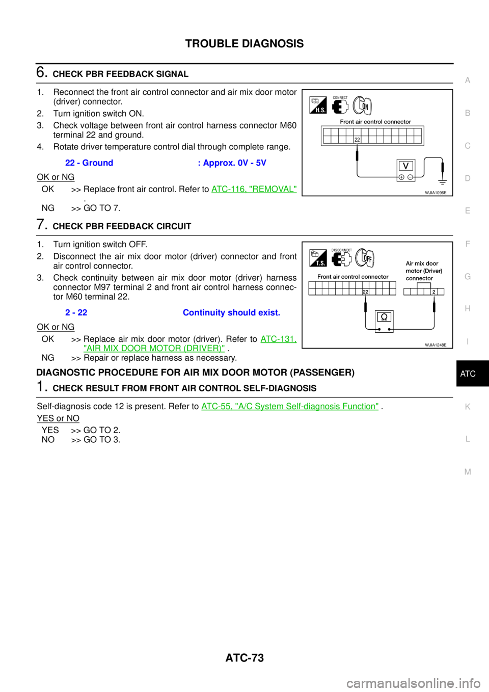
6.CHECK PBR FEEDBACK SIGNAL
1. Reconnect the front air control connector and air mix door motor
(driver) connector.
2. Turn ignition switch ON.
3. Check voltage between front air control harness connector M60
terminal 22 and ground.
4. Rotate driver temperature control dial through complete range.
OK or NG
OK >> Replace front air control. Refer toAT C - 11 6 , "REMOVAL"
.
NG >> GO TO 7.
7.CHECK PBR FEEDBACK CIRCUIT
1. Turn ignition switch OFF.
2. Disconnect the air mix door motor (driver) connector and front
air control connector.
3. Check continuity between air mix door motor (driver) harness
connector M97 terminal 2 and front air control harness connec-
tor M60 terminal 22.
OK or NG
OK >> Replace air mix door motor (driver). Refer toATC-131,
"AIR MIX DOOR MOTOR (DRIVER)".
NG >> Repair or replace harness as necessary.
DIAGNOSTIC PROCEDURE FOR AIR MIX DOOR MOTOR (PASSENGER)
1.CHECK RESULT FROM FRONT AIR CONTROL SELF-DIAGNOSIS
Self-diagnosis code 12 is present. Refer toAT C - 5 5 , "
A/C System Self-diagnosis Function".
YES or NO
YES >> GO TO 2.
NO >> GO TO 3.22 - Ground : Approx. 0V - 5V
WJIA1096E
2 - 22 Continuity should exist.
WJIA1248E
Page 408 of 3171
ATC-74
TROUBLE DIAGNOSIS
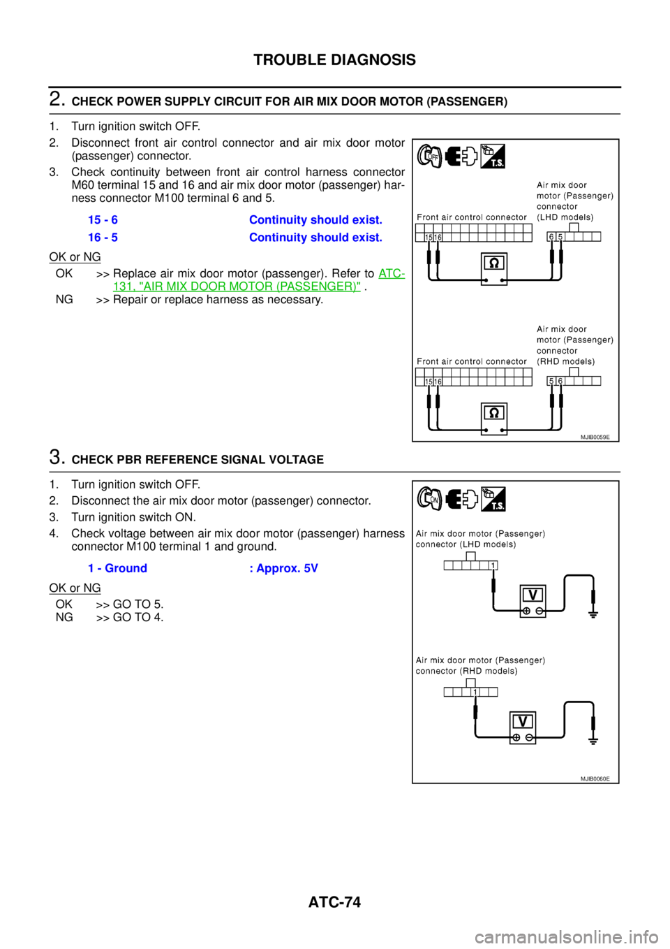
2.CHECK POWER SUPPLY CIRCUIT FOR AIR MIX DOOR MOTOR (PASSENGER)
1. Turn ignition switch OFF.
2. Disconnect front air control connector and air mix door motor
(passenger) connector.
3. Check continuity between front air control harness connector
M60 terminal 15 and 16 and air mix door motor (passenger) har-
ness connector M100 terminal 6 and 5.
OK or NG
OK >> Replace air mix door motor (passenger). Refer toAT C -
131, "AIR MIX DOOR MOTOR (PASSENGER)".
NG >> Repair or replace harness as necessary.
3.CHECK PBR REFERENCE SIGNAL VOLTAGE
1. Turn ignition switch OFF.
2. Disconnect the air mix door motor (passenger) connector.
3. Turn ignition switch ON.
4. Check voltage between air mix door motor (passenger) harness
connector M100 terminal 1 and ground.
OK or NG
OK >> GO TO 5.
NG >> GO TO 4.15 - 6 Continuity should exist.
16 - 5 Continuity should exist.
MJIB0059E
1 - Ground : Approx. 5V
MJIB0060E
Page 409 of 3171
TROUBLE DIAGNOSIS
ATC-75
C
D
E
F
G
H
I
K
L
MA
B
AT C
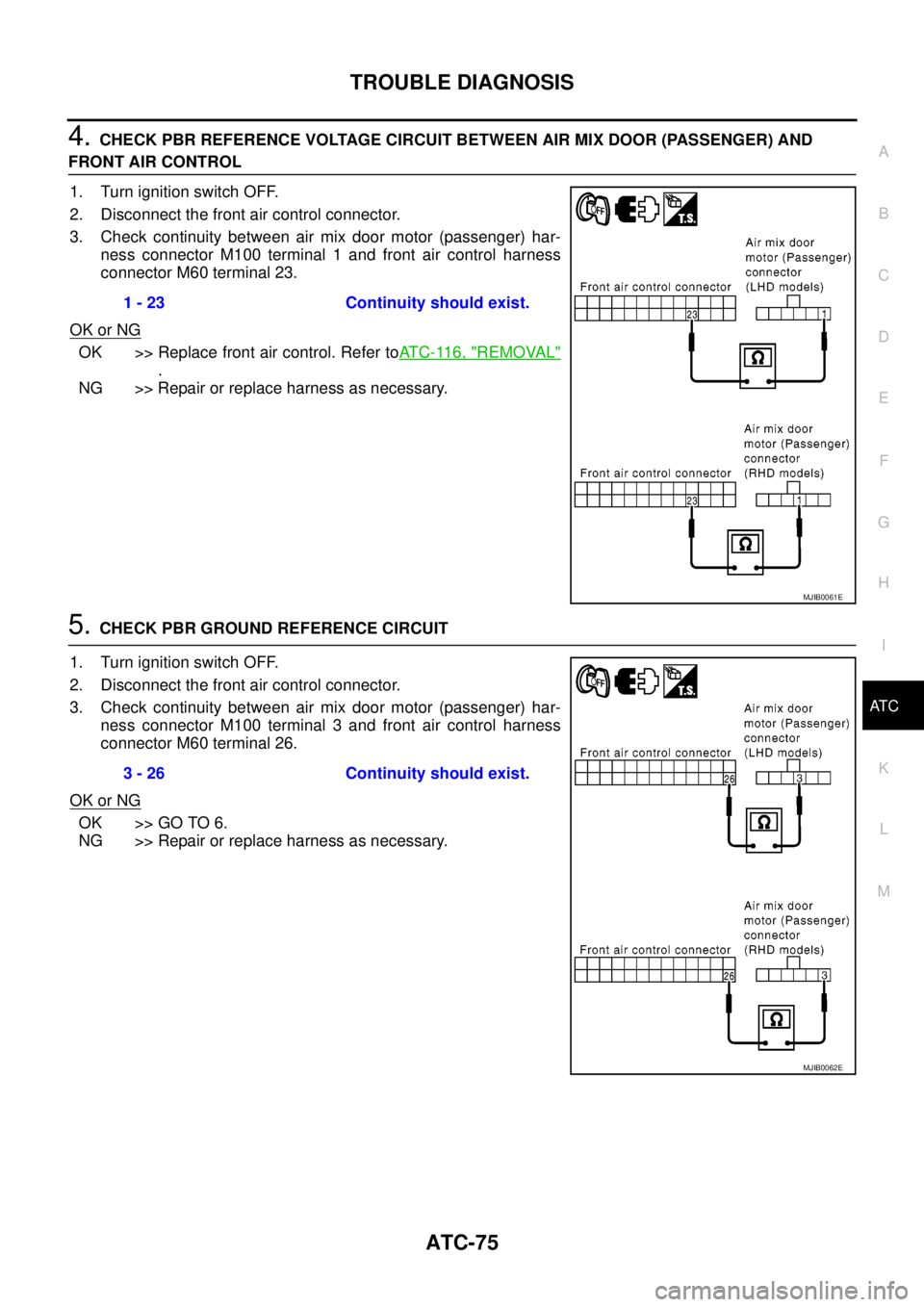
4.CHECK PBR REFERENCE VOLTAGE CIRCUIT BETWEEN AIR MIX DOOR (PASSENGER) AND
FRONT AIR CONTROL
1. Turn ignition switch OFF.
2. Disconnect the front air control connector.
3. Check continuity between air mix door motor (passenger) har-
ness connector M100 terminal 1 and front air control harness
connector M60 terminal 23.
OK or NG
OK >> Replace front air control. Refer toAT C - 11 6 , "REMOVAL"
.
NG >> Repair or replace harness as necessary.
5.CHECK PBR GROUND REFERENCE CIRCUIT
1. Turn ignition switch OFF.
2. Disconnect the front air control connector.
3. Check continuity between air mix door motor (passenger) har-
ness connector M100 terminal 3 and front air control harness
connector M60 terminal 26.
OK or NG
OK >> GO TO 6.
NG >> Repair or replace harness as necessary.1 - 23 Continuity should exist.
MJIB0061E
3 - 26 Continuity should exist.
MJIB0062E
Page 410 of 3171
ATC-76
TROUBLE DIAGNOSIS
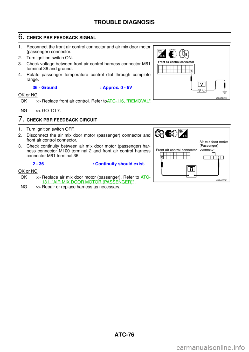
6.CHECK PBR FEEDBACK SIGNAL
1. Reconnect the front air control connector and air mix door motor
(passenger) connector.
2. Turn ignition switch ON.
3. Check voltage between front air control harness connector M61
terminal 36 and ground.
4. Rotate passenger temperature control dial through complete
range.
OK or NG
OK >> Replace front air control. Refer toAT C - 11 6 , "REMOVAL"
.
NG >> GO TO 7.
7.CHECK PBR FEEDBACK CIRCUIT
1. Turn ignition switch OFF.
2. Disconnect the air mix door motor (passenger) connector and
front air control connector.
3. Check continuity between air mix door motor (passenger) har-
ness connector M100 terminal 2 and front air control harness
connector M61 terminal 36.
OK or NG
OK >> Replace air mix door motor (passenger). Refer toAT C -
131, "AIR MIX DOOR MOTOR (PASSENGER)".
NG >> Repair or replace harness as necessary.36 - Ground : Approx. 0 - 5V
WJIA1249E
2 - 36 : Continuity should exist.
MJIB0063E