stop start NISSAN NAVARA 2005 Repair Service Manual
[x] Cancel search | Manufacturer: NISSAN, Model Year: 2005, Model line: NAVARA, Model: NISSAN NAVARA 2005Pages: 3171, PDF Size: 49.59 MB
Page 1386 of 3171

EM-4
PRECAUTIONS
PRECAUTIONS
PFP:00001
Precautions for Draining Engine CoolantEBS01E5H
Drain engine coolant when engine is cooled.
Precautions for Disconnecting Fuel PipingEBS01E5I
lBefore starting work, make sure no fire or spark producing items are in the work area.
lAfter disconnecting pipes, plug openings to stop fuel leakage.
Precautions for Removal and DisassemblyEBS01E5J
lWhen instructed to use SST, use the specified tools. Always be careful to work safely, avoid forceful or
uninstructed operations.
lExercise maximum care to avoid damage to mating or sliding surfaces.
lCover openings of engine system with tape or the equivalent, if necessary, to seal out foreign materials.
lMark and arrange disassembly parts in an organized way for easy troubleshooting and re-assembly.
lWhen loosening nuts and bolts, as a basic rule, start with the one furthest outside, then the one diagonally
opposite, and so on. If the order of loosening is specified, do exactly as specified.
Precautions for Inspection, Repair and ReplacementEBS01E5K
Before repairing or replacing, thoroughly inspect parts. Inspect new replacement parts in the same way, and
replace if necessary.
Precautions for Assembly and InstallationEBS01E5L
lUsetorquewrenchtotightenboltsornutstospecification.
lWhen tightening nuts and bolts, as a basic rule, equally tighten in several different steps starting with the
ones in center, then ones on inside and outside diagonally in this order. If the order of tightening is speci-
fied, do exactly as specified.
lReplace with new liquid gasket, packing, oil seal or O-ring.
lDowel pins are used for several parts alignment. When replacing and reassembling parts with dowel pins,
make sure that dowel pins are installed in the original position.
lThoroughly wash, clean, and air-blow each part. Carefully check engine oil or engine coolant passages for
any restriction and blockage.
lAvoid damaging sliding or mating surfaces. Completely remove foreign materials such as cloth lint or dust.
Before assembly, oil sliding surfaces well.
lRelease air within route when refilling after draining engine coolant.
lAfter repairing, start engine and increase engine speed to check engine coolant, fuel, engine oil, and
exhaust systems for leakage.
Parts Requiring Angle TighteningEBS01E5M
lUse an angle wrench [SST: KV10112100] for the final tightening of the following engine parts:
–Cylinder head bolts
–Main bearing cap bolts
–Connecting rod cap nuts
–Crankshaft pulley bolt (No angle wrench is required as the bolt flange is provided with notches for angle
tightening)
lDo not use a torque value for final tightening.
lThe torque value for these parts are for a preliminary step.
lEnsure thread and seat surfaces are clean and coated with engine oil.
Page 1407 of 3171
INTAKE MANIFOLD
EM-25
C
D
E
F
G
H
I
J
K
L
MA
EM
–When an insert stopper is not provided with the pipe, insert the hose up to dimension A. When the pipe is
shorter than dimension A, insert hose fully until it reaches the end.
–When an insert stopper is provided on the pipe side, insert the hose until it reaches the stopper.
lBefore starting engine, bleed air from fuel piping. Refer toFL-5, "Air Bleeding".
INSPECTION AFTER INSTALLATION
Start engine and increase engine speed to check for fuel leak.
CAUTION:
Do not touch the engine immediately after stopped as engine becomes extremely hot.
NOTE:
Use mirrors for checking at points out of clear sight.Dimension A : 15 – 20 mm (0.591 – 0.787 in)
Page 1422 of 3171
EM-40
OIL PAN AND OIL STRAINER
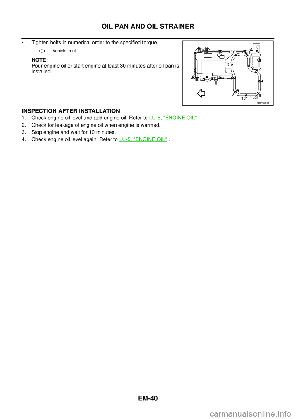
• Tighten bolts in numerical order to the specified torque.
NOTE:
Pour engine oil or start engine at least 30 minutes after oil pan is
installed.
INSPECTION AFTER INSTALLATION
1. Check engine oil level and add engine oil. Refer toLU-5, "ENGINE OIL".
2. Check for leakage of engine oil when engine is warmed.
3. Stop engine and wait for 10 minutes.
4. Check engine oil level again. Refer toLU-5, "
ENGINE OIL".
: Vehicle front
PBIC3425E
Page 1430 of 3171
EM-48
INJECTION TUBE AND FUEL INJECTOR
NOTE:
Intake manifold and other related parts are omitted for explanation.
9. Install remaining parts in the reverse order of removal.
INSPECTION AFTER INSTALLATION
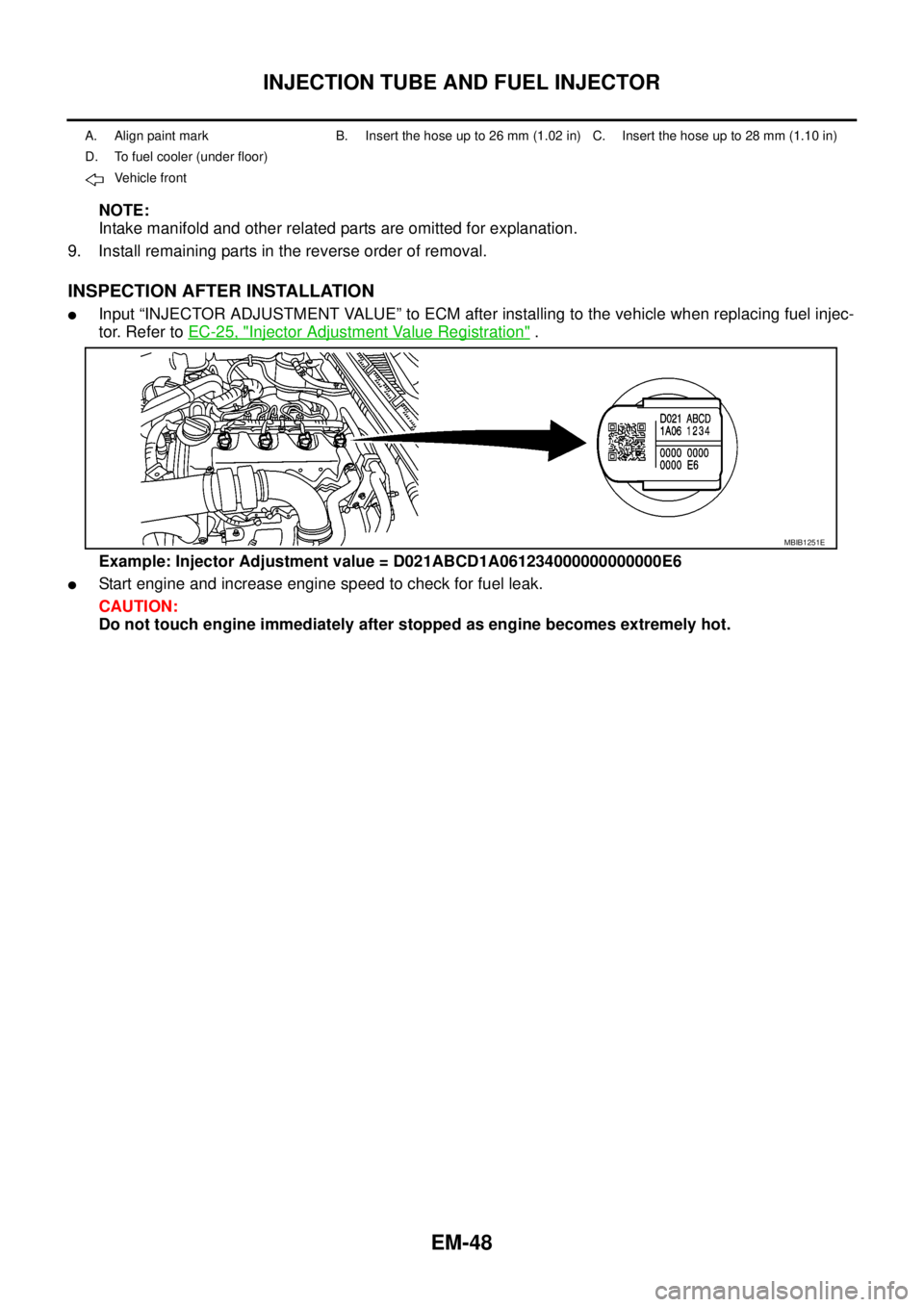
lInput “INJECTOR ADJUSTMENT VALUE” to ECM after installing to the vehicle when replacing fuel injec-
tor. Refer toEC-25, "
Injector Adjustment Value Registration".
Example: Injector Adjustment value = D021ABCD1A061234000000000000E6
lStart engine and increase engine speed to check for fuel leak.
CAUTION:
Do not touch engine immediately after stopped as engine becomes extremely hot.
A. Align paint mark B. Insert the hose up to 26 mm (1.02 in) C. Insert the hose up to 28 mm (1.10 in)
D. To fuel cooler (under floor)
Ve h ic le f ro n t
MBIB1251E
Page 1440 of 3171
EM-58
ROCKER COVER
INSPECTION AFTER INSTALLATION
Start engine and increase engine speed to check for fuel leak and engine oil leak.
CAUTION:
Do not touch the engine immediately after stopped as engine becomes extremely hot.
Page 1447 of 3171
CAMSHAFT
EM-65
C
D
E
F
G
H
I
J
K
L
MA
EM
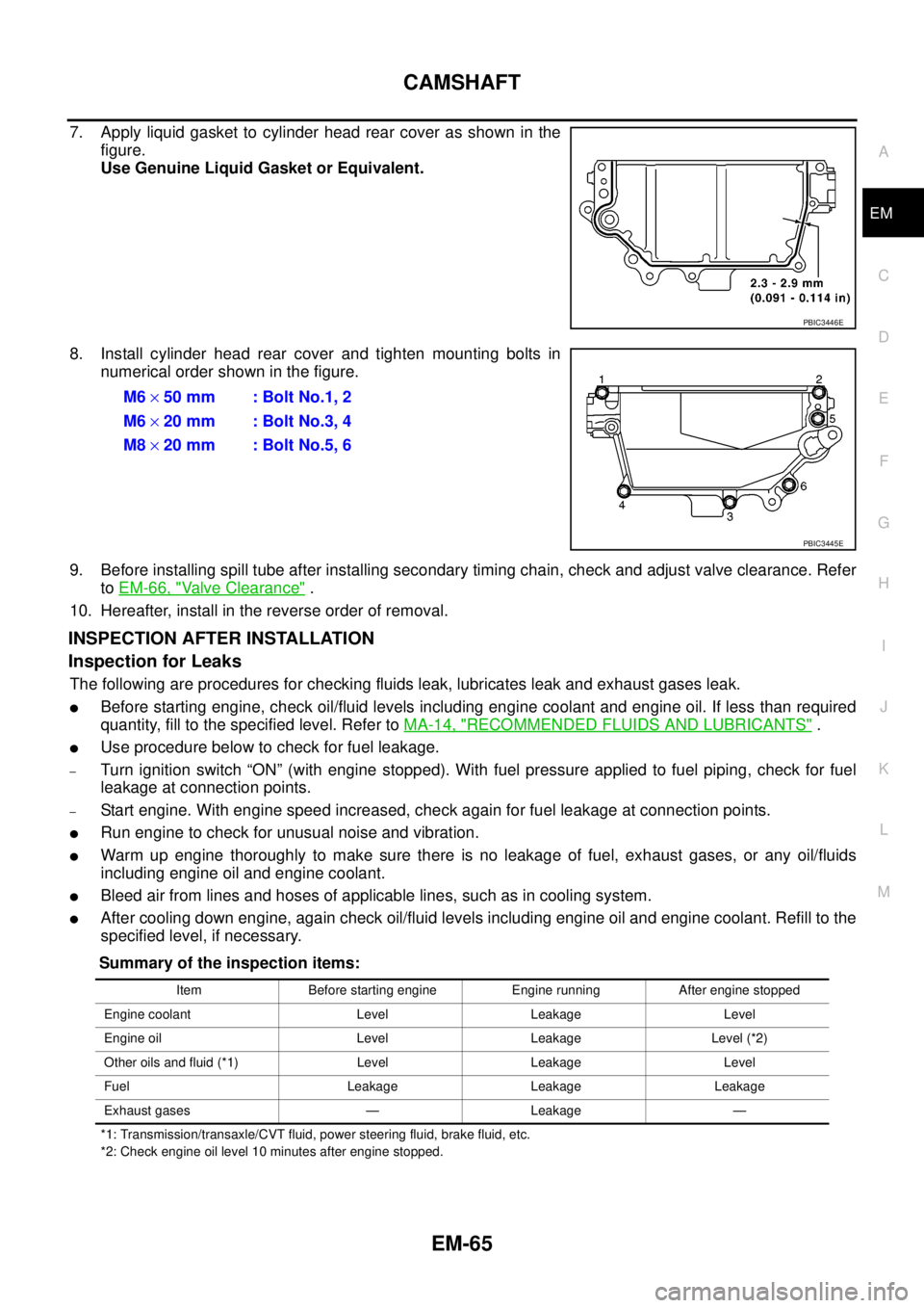
7. Apply liquid gasket to cylinder head rear cover as shown in the
figure.
Use Genuine Liquid Gasket or Equivalent.
8. Install cylinder head rear cover and tighten mounting bolts in
numerical order shown in the figure.
9. Before installing spill tube after installing secondary timing chain, check and adjust valve clearance. Refer
toEM-66, "
Valve Clearance".
10. Hereafter, install in the reverse order of removal.
INSPECTION AFTER INSTALLATION
Inspection for Leaks
The following are procedures for checking fluids leak, lubricates leak and exhaust gases leak.
lBefore starting engine, check oil/fluid levels including engine coolant and engine oil. If less than required
quantity, fill to the specified level. Refer toMA-14, "
RECOMMENDED FLUIDS AND LUBRICANTS".
lUse procedure below to check for fuel leakage.
–Turn ignition switch “ON” (with engine stopped). With fuel pressure applied to fuel piping, check for fuel
leakage at connection points.
–Start engine. With engine speed increased, check again for fuel leakage at connection points.
lRun engine to check for unusual noise and vibration.
lWarm up engine thoroughly to make sure there is no leakage of fuel, exhaust gases, or any oil/fluids
including engine oil and engine coolant.
lBleed air from lines and hoses of applicable lines, such as in cooling system.
lAfter cooling down engine, again check oil/fluid levels including engine oil and engine coolant. Refill to the
specified level, if necessary.
Summary of the inspection items:
*1: Transmission/transaxle/CVT fluid, power steering fluid, brake fluid, etc.
*2: Check engine oil level 10 minutes after engine stopped.
PBIC3446E
M6´50 mm : Bolt No.1, 2
M6´20 mm : Bolt No.3, 4
M8´20 mm : Bolt No.5, 6
PBIC3445E
Item Before starting engine Engine running After engine stopped
Engine coolant Level Leakage Level
Engine oil Level Leakage Level (*2)
Other oils and fluid (*1) Level Leakage Level
Fuel Leakage Leakage Leakage
Exhaust gases — Leakage —
Page 1450 of 3171
![NISSAN NAVARA 2005 Repair Service Manual EM-68
CAMSHAFT
4. Withvalvespringinacompressedstate,removethecamshaft
pliers [SST] by securely setting the outer circumference of the
valve lifter with the end of the lifter stopper [SST].
lHold the l NISSAN NAVARA 2005 Repair Service Manual EM-68
CAMSHAFT
4. Withvalvespringinacompressedstate,removethecamshaft
pliers [SST] by securely setting the outer circumference of the
valve lifter with the end of the lifter stopper [SST].
lHold the l](/img/5/57362/w960_57362-1449.png)
EM-68
CAMSHAFT
4. Withvalvespringinacompressedstate,removethecamshaft
pliers [SST] by securely setting the outer circumference of the
valve lifter with the end of the lifter stopper [SST].
lHold the lifter stopper by hand until the shim is removed.
CAUTION:
Do not retrieve the camshaft pliers forcefully, as cam-
shaft will be damaged.
5. Move the round hole of adjusting shim to the front with the very
thin screwdriver or like that.
lWhen adjusting shim on valve lifter will not rotate smoothly,
restart from step 3 to release the end of the lifter stopper
[SST] from touching adjusting shim.
6. Remove adjusting shim from valve lifter by blowing air through
the round hole of the adjusting shim with the air gun.
CAUTION:
To prevent any remaining engine oil from being blown
around, thoroughly wipe the area clean and wear protective
goggles.
7. Remove adjusting shim by using the magnet hand.
8. Measure the thickness of adjusting shim using the micrometer.
lMeasure near the center of the shim (the part that touches
camshaft).
9. Select the new adjusting shim from the following methods.
PBIC2322E
PBIC2323E
PBIC2324E
FEM032
Calculation method of the adjusting shim thickness:
R = Thickness of removed shim
N = Thickness of new shim
M = Measured valve clearance
Intake
N=R+[M-0.28mm(0.0010in)]
Exhaust
N=R+[M-0.30mm(0.0118in)]
Page 1459 of 3171
SECONDARY TIMING CHAIN
EM-77
C
D
E
F
G
H
I
J
K
L
MA
EM
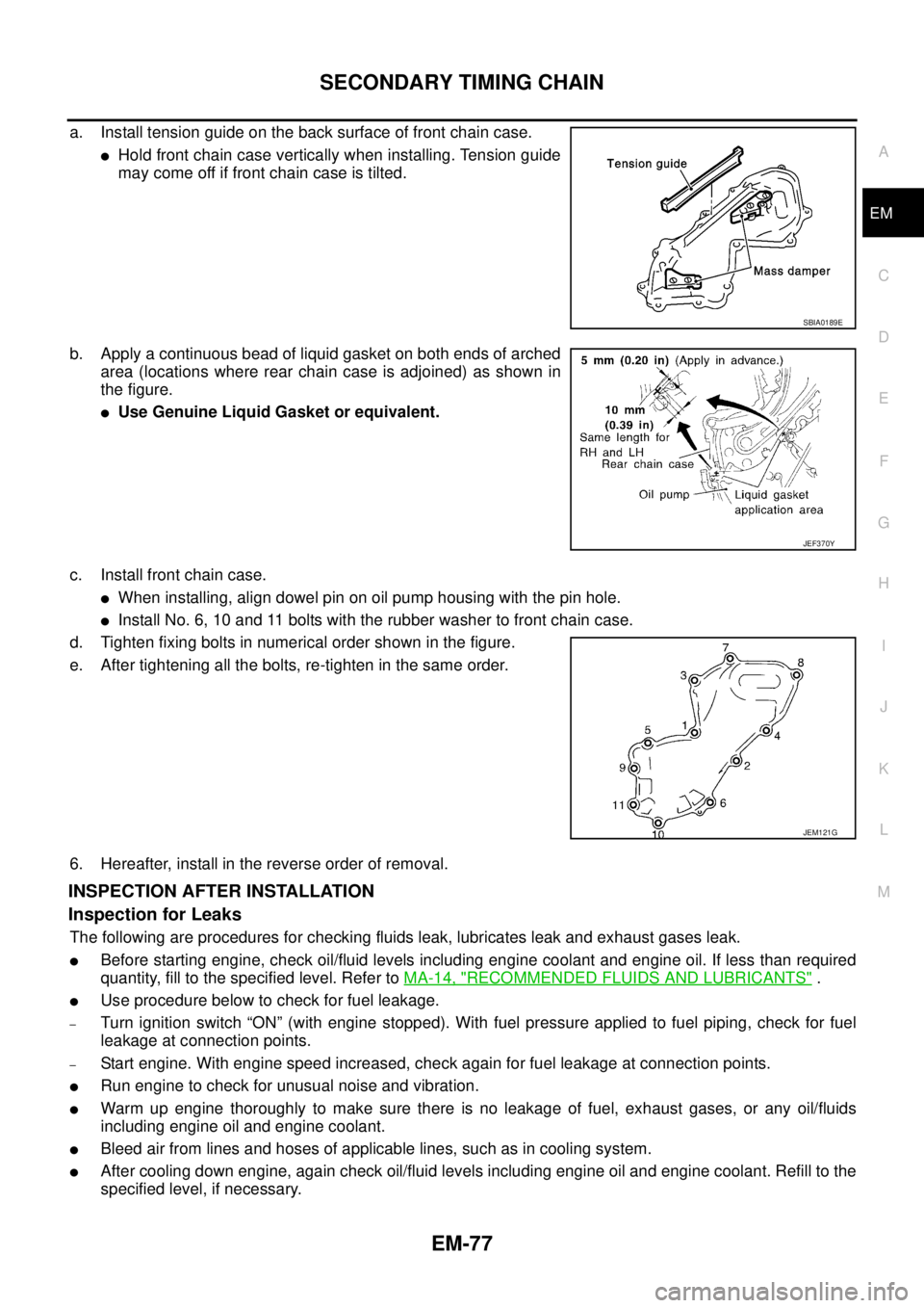
a. Install tension guide on the back surface of front chain case.
lHold front chain case vertically when installing. Tension guide
may come off if front chain case is tilted.
b. Apply a continuous bead of liquid gasket on both ends of arched
area (locations where rear chain case is adjoined) as shown in
the figure.
lUse Genuine Liquid Gasket or equivalent.
c. Install front chain case.
lWhen installing, align dowel pin on oil pump housing with the pin hole.
lInstall No. 6, 10 and 11 bolts with the rubber washer to front chain case.
d. Tighten fixing bolts in numerical order shown in the figure.
e. After tightening all the bolts, re-tighten in the same order.
6. Hereafter, install in the reverse order of removal.
INSPECTION AFTER INSTALLATION
Inspection for Leaks
The following are procedures for checking fluids leak, lubricates leak and exhaust gases leak.
lBefore starting engine, check oil/fluid levels including engine coolant and engine oil. If less than required
quantity, fill to the specified level. Refer toMA-14, "
RECOMMENDED FLUIDS AND LUBRICANTS".
lUse procedure below to check for fuel leakage.
–Turn ignition switch “ON” (with engine stopped). With fuel pressure applied to fuel piping, check for fuel
leakage at connection points.
–Start engine. With engine speed increased, check again for fuel leakage at connection points.
lRun engine to check for unusual noise and vibration.
lWarm up engine thoroughly to make sure there is no leakage of fuel, exhaust gases, or any oil/fluids
including engine oil and engine coolant.
lBleed air from lines and hoses of applicable lines, such as in cooling system.
lAfter cooling down engine, again check oil/fluid levels including engine oil and engine coolant. Refill to the
specified level, if necessary.
SBIA0189E
JEF370Y
JEM121G
Page 1460 of 3171

EM-78
SECONDARY TIMING CHAIN
Summary of the inspection items:
*1: Transmission/transaxle/CVT fluid, power steering fluid, brake fluid, etc.
*2: Check engine oil level 10 minutes after engine stopped.Item Before starting engine Engine running After engine stopped
Engine coolant Level Leakage Level
Engine oil Level Leakage Level (*2)
Other oils and fluid (*1) Level Leakage Level
Fuel Leakage Leakage Leakage
Exhaust gases — Leakage —
Page 1473 of 3171
PRIMARY TIMING CHAIN
EM-91
C
D
E
F
G
H
I
J
K
L
MA
EM
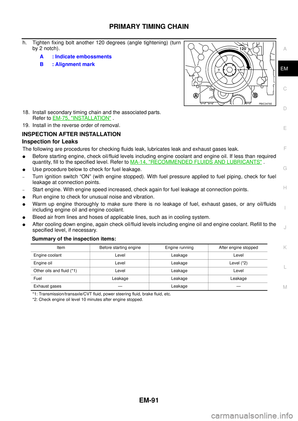
h. Tighten fixing bolt another 120 degrees (angle tightening) (turn
by 2 notch).
18. Install secondary timing chain and the associated parts.
Refer toEM-75, "
INSTALLATION".
19. Install in the reverse order of removal.
INSPECTION AFTER INSTALLATION
Inspection for Leaks
The following are procedures for checking fluids leak, lubricates leak and exhaust gases leak.
lBefore starting engine, check oil/fluid levels including engine coolant and engine oil. If less than required
quantity, fill to the specified level. Refer toMA-14, "
RECOMMENDED FLUIDS AND LUBRICANTS".
lUse procedure below to check for fuel leakage.
–Turn ignition switch “ON” (with engine stopped). With fuel pressure applied to fuel piping, check for fuel
leakage at connection points.
–Start engine. With engine speed increased, check again for fuel leakage at connection points.
lRun engine to check for unusual noise and vibration.
lWarm up engine thoroughly to make sure there is no leakage of fuel, exhaust gases, or any oil/fluids
including engine oil and engine coolant.
lBleed air from lines and hoses of applicable lines, such as in cooling system.
lAfter cooling down engine, again check oil/fluid levels including engine oil and engine coolant. Refill to the
specified level, if necessary.
Summary of the inspection items:
*1: Transmission/transaxle/CVT fluid, power steering fluid, brake fluid, etc.
*2: Check engine oil level 10 minutes after engine stopped.
A : Indicate embossments
B : Alignment mark
PBIC3476E
Item Before starting engine Engine running After engine stopped
Engine coolant Level Leakage Level
Engine oil Level Leakage Level (*2)
Other oils and fluid (*1) Level Leakage Level
Fuel Leakage Leakage Leakage
Exhaust gases — Leakage —