stop start NISSAN NAVARA 2005 Repair Owner's Manual
[x] Cancel search | Manufacturer: NISSAN, Model Year: 2005, Model line: NAVARA, Model: NISSAN NAVARA 2005Pages: 3171, PDF Size: 49.59 MB
Page 827 of 3171
![NISSAN NAVARA 2005 Repair Owners Manual SYSTEM DESCRIPTION
BRC-5
[ABS]
C
D
E
G
H
I
J
K
L
MA
B
BRC
SYSTEM DESCRIPTIONPFP:00000
System DiagramEFS005TJ
FunctionsEFS005TK
ABS
lThe Anti-Lock Brake System is a function that detects wheel revoluti NISSAN NAVARA 2005 Repair Owners Manual SYSTEM DESCRIPTION
BRC-5
[ABS]
C
D
E
G
H
I
J
K
L
MA
B
BRC
SYSTEM DESCRIPTIONPFP:00000
System DiagramEFS005TJ
FunctionsEFS005TK
ABS
lThe Anti-Lock Brake System is a function that detects wheel revoluti](/img/5/57362/w960_57362-826.png)
SYSTEM DESCRIPTION
BRC-5
[ABS]
C
D
E
G
H
I
J
K
L
MA
B
BRC
SYSTEM DESCRIPTIONPFP:00000
System DiagramEFS005TJ
FunctionsEFS005TK
ABS
lThe Anti-Lock Brake System is a function that detects wheel revolution while braking, and it improves
handling stability during sudden braking by electrically preventing 4 wheels lock. Maneuverability is also
improved for avoiding obstacles.
lElectrical system diagnosis by CONSULT-II is available.
EBD
lElectronic Brake Distributor is a function that detects subtle slippages between the front and rear tyre dur-
ing braking, and it improves handling stability by electrically controlling the brake fluid pressure which
results in reduced rear tyre slippage.
lElectrical system diagnosis by CONSULT-II is available.
Operation That Is Not “System Error”EFS005TL
ABS
lWhen starting engine or just after starting vehicle, brake pedal may vibrate or the motor operating noise
may be heard from engine room. This is a normal states of the operation check.
lDuring ABS operation, brake pedal lightly vibrates and a mechanical noise may be heard. This is normal.
lStopping distance may be longer than that of vehicles without ABS when vehicle drives on rough, gravel,
or snow-covered (fresh, deep snow) roads.
Fail-Safe FunctionEFS005TM
ABS, EBD SYSTEM
In case of electrical malfunction with ABS, ABS warning lamp will turn on. In case of electrical incidents with
EBD, brake warning lamp and ABS warning lamp will turn on. Simultaneously, ABS become one of following
conditions of Fail-Safe function.
1. For ABS malfunction, only EBD is activated and condition of vehicle is same condition of vehicles without
ABS system.
NOTE:
ABS self-diagnosis sound may be heard.That is a normal condition because a self-diagnosis for “Ignition
switch ON” and “The first starting” are being performed.
2. For EBD malfunction, EBD and ABS become inoperative, and condition of vehicle is same as condition of
vehicles without ABS, EBD system.
SFIA3001E
Page 840 of 3171
![NISSAN NAVARA 2005 Repair Owners Manual BRC-18
[ABS]
TROUBLE DIAGNOSIS
Self-Diagnosis
EFS005TU
OPERATION PROCEDURE
1. Turn ignition switch OFF.
2. Connect CONSULT-II and CONSULT-II CONVERTER to data link connector.
3. Turn ignition switch O NISSAN NAVARA 2005 Repair Owners Manual BRC-18
[ABS]
TROUBLE DIAGNOSIS
Self-Diagnosis
EFS005TU
OPERATION PROCEDURE
1. Turn ignition switch OFF.
2. Connect CONSULT-II and CONSULT-II CONVERTER to data link connector.
3. Turn ignition switch O](/img/5/57362/w960_57362-839.png)
BRC-18
[ABS]
TROUBLE DIAGNOSIS
Self-Diagnosis
EFS005TU
OPERATION PROCEDURE
1. Turn ignition switch OFF.
2. Connect CONSULT-II and CONSULT-II CONVERTER to data link connector.
3. Turn ignition switch ON.
4. Start engine and drive vehicle at 30 km/h (19 MPH) or more for approximately 1 minute.
5. After stopping vehicle, with engine running, touch “START (NISSAN BASED VHCL)”, “ABS”, “SELF-DIAG
RESULTS” in order on CONSULT-II screen.
CAUTION:
If “START (NISSAN BASED VHCL)” is touched immediately after starting engine or turn on the
ignition switch, “ABS” might not be displayed in the “SELECT SYSTEM” screen. In this case,
repeat the operation from step 1.
6. The self-diagnostic results are displayed. (Touch “PRINT” to print out self-diagnostic results, If necessary.)
lCheck ABS warning lamp if “NO FAILURE” is displayed.
7. Perform the appropriate inspection from display item list, and repair or replace the malfunctioning compo-
nent. Refer toBRC-18, "
Display Item List".
8. Start engine and drive vehicle at 30 km/h (19 MPH) or more for approximately 1 minute.
CAUTION:
When the wheel sensor malfunctions, after inspecting the wheel sensor system, the ABS warning
lamp and brake warning lamp will not turn off even when the system is normal unless the vehicle
is driving at 30 km/h (19MPH) or more for approximately 1 minute.
ERASE MEMORY
1. Turn ignition switch OFF.
2. Start engine and touch “START (NISSAN BASED VHCL)”, “ABS”, “SELF-DIAG RESULTS”, “ERASE
MEMORY” in order on CONSULT-II screen to erase the error memory.
If “ABS” is not indicated, go toGI-50, "
CONSULT-II Data Link Connector (DLC) Circuit".
CAUTION:
If the error memory is not erased, re-perform the operation from step 4.
3. Perform self-diagnosis again, and make sure that diagnostic memory is erased.
4. Drive vehicle at 30 km/h (19 MPH) or more for approximately 1 minute as the final inspection, and make
sure that the ABS warning lamp turn off.
DISPLAY ITEM LIST
Self-diagnostic item Malfunction detecting condition Check system
RR RH SENSOR-1 Circuit of rear RH wheel sensor is open.
BRC-24, "
Inspection 1
Wheel Sensor System"
(Note 1) RR LH SENSOR-1 Circuit of rear LH wheel sensor is open.
FR RH SENSOR-1 Circuit of front RH wheel sensor is open.
FR LH SENSOR-1 Circuit of front LH wheel sensor is open.
RR RH SENSOR-2When the circuit in the rear RH wheel sensor is short-circuited. Or
when the sensor power voltage is outside the standard. When the
distance between the wheel sensor and sensor rotor is too large
and the sensor pulse cannot be recognized by the control unit.
RR LH SENSOR-2When the circuit in the rear LH wheel sensor is short-circuited. Or
when the sensor power voltage is outside the standard. When the
distance between the wheel sensor and sensor rotor is too large
and the sensor pulse cannot be recognized by the control unit.
FR RH SENSOR-2When the circuit in the front RH wheel sensor is short-circuited. Or
when the sensor power voltage is outside the standard. When the
distance between the wheel sensor and sensor rotor is too large
and the sensor pulse cannot be recognized by the control unit.
FR LH SENSOR-2When the circuit in the front LH wheel sensor is short-circuited. Or
when the sensor power voltage is outside the standard. When the
distance between the wheel sensor and sensor rotor is too large
and the sensor pulse cannot be recognized by the control unit.
Page 842 of 3171
![NISSAN NAVARA 2005 Repair Owners Manual BRC-20
[ABS]
TROUBLE DIAGNOSIS
Data Monitor
EFS005TV
OPERATION PROCEDURE
1. Touch “START (NISSAN BASED VHCL)”, “ABS”, “DATA MONITOR” in order on CONSULT-II screen.
CAUTION:
When “START ( NISSAN NAVARA 2005 Repair Owners Manual BRC-20
[ABS]
TROUBLE DIAGNOSIS
Data Monitor
EFS005TV
OPERATION PROCEDURE
1. Touch “START (NISSAN BASED VHCL)”, “ABS”, “DATA MONITOR” in order on CONSULT-II screen.
CAUTION:
When “START (](/img/5/57362/w960_57362-841.png)
BRC-20
[ABS]
TROUBLE DIAGNOSIS
Data Monitor
EFS005TV
OPERATION PROCEDURE
1. Touch “START (NISSAN BASED VHCL)”, “ABS”, “DATA MONITOR” in order on CONSULT-II screen.
CAUTION:
When “START (NISSAN BASED VHCL)” is touched immediately after starting engine or turning on
ignition switch, “ABS” might not be displayed in “SELECT SYSTEM” screen. In this case, repeat
the operation from step 1.
2. At the monitor item selection screen, touch one of the item “ECU INPUT SIGNALS”, “MAIN SIGNALS” or
“SELECTION FROM MENU”.
3. Touch “START” to proceed to the data monitor screen.
DISPLAY ITEM LIST
CAUTION:
The display shows the control unit calculation data, so a normal value might be displayed even in the
event the output circuit (harness) is open or short-circuited.
E:ECU INPUT SIGNALS M:MAIN SIGNALS S:SELECTION FROM MENU
SELECT
MONITOR
ITEMMonitor item Display contentData monitor
ConditionReference value in
normal operation
E, M, SFR LH SENSOR
FR RH SENSOR
RR LH SENSOR
RR RH SENSORWheel speed0 [km/h] Vehicle stopped
Nearly matches the speed-
ometer display (±10% or
less)Vehicle running
(Note 1)
E, M, S STOP LAMP SW Brake pedal operationBrake pedal depressed ON
Brake pedal not depressed OFF
E, M, S BATTERY VOLTBattery voltage supplied to the ABS
actuator and electric unit (control
unit)Ignitionswitch ON 10–16V
M, SFR RH IN SOL
FR RH OUT SOL
FR LH IN SOL
FR LH OUT SOL
RR RH IN SOL
RR RH OUT SOL
RR LH IN SOL
RR LH OUT SOLOperation status of all solenoid
valveActuator (solenoid valve) is
active (“Active Test ”with
CONSULT-II) or actuator
relay is inactive (in fail-safe
mode).ON
When the actuator (sole-
noid valve) is not active
and actuator relay is active
(ignition switch ON).OFF
M, S MOTOR RELAYMotor and motor relay operation
statusWhen the motor relay and
motor are operatingON
When the motor relay and
motor are not operatingOFF
M, S ACTUATOR RLY Actuator relay operation statusWhen the actuator relay is
operatingON
When the actuator relay is
not operatingOFF
M, S ABS WARN LAMPABS warning lamp status
(Note 2)When ABS warning lamp is
ON.ON
When ABS warning lamp is
OFF.OFF
S EBD WARN LAMP Brake warning lamp status (Note 2)Brake warning lamp ON ON
Brake warning lamp OFF OFF
S EBD SIGNAL EBD operationEBD active ON
EBD not active OFF
Page 843 of 3171
![NISSAN NAVARA 2005 Repair Owners Manual TROUBLE DIAGNOSIS
BRC-21
[ABS]
C
D
E
G
H
I
J
K
L
MA
B
BRC
Note 1:Confirm tyre pressure is normal.
Note 2:On and off timing for warning lamp and indicator lamp. Refer toBRC-24, "
BASIC INSPECTION 3 ABS NISSAN NAVARA 2005 Repair Owners Manual TROUBLE DIAGNOSIS
BRC-21
[ABS]
C
D
E
G
H
I
J
K
L
MA
B
BRC
Note 1:Confirm tyre pressure is normal.
Note 2:On and off timing for warning lamp and indicator lamp. Refer toBRC-24, "
BASIC INSPECTION 3 ABS](/img/5/57362/w960_57362-842.png)
TROUBLE DIAGNOSIS
BRC-21
[ABS]
C
D
E
G
H
I
J
K
L
MA
B
BRC
Note 1:Confirm tyre pressure is normal.
Note 2:On and off timing for warning lamp and indicator lamp. Refer toBRC-24, "
BASIC INSPECTION 3 ABS WARNING LAMP AND
BRAKE WARNING LAMP INSPECTION".
Active TestEFS005TW
CAUTION:
lDo not perform active test while driving vehicle.
lMake sure to completely bleed air from brake system.
lActive test cannot be performed when ABS warning lamp is on.
lABS and brake warming lamps turn on during active test.
OPERATION PROCEDURE
1. Touch START (NISSAN BASED VHCL), “ABS”, “ACTIVE TEST” in order on CONSULT-II screen.
If “ABS” is not indicated, go toGI-50, "
CONSULT-II Data Link Connector (DLC) Circuit".
CAUTION:
When “START (NISSAN BASED VHCL)” is touched immediately after starting engine or turning on
ignition switch, “ABS” might not be displayed in the “SELECT SYSTEM” screen. In this case,
repeat the operation from step 1.
2. Touch “SELECT TEST ITEM” is displayed.
3. Touch necessary test item.
4. While “MAIN SIGNALS” indication is inverted, touch “START”.
5. “ACTIVE TEST” screen will be displayed so perform the following test.
lSolenoid valve
lABS motor
NOTE:
lWhen active test is performed while depressing the pedal, the pedal depression amount will
change.This is normal.
l“TEST IS STOPPED” is displayed 10 seconds after operation start.
lAfter “TEST IS STOPPED” is displayed, to perform test again, touch “BACK” and repeat step 3.
S ABS SIGNAL ABS operationABS active ON
ABS not active OFF
SEBD FAIL SIG
ABS FAIL SIGSystem error signal statusMalfunctions condition
(When system is malfunc-
tioning)OFF
S CRANKING SIG CRANKING statusCranking ON
Not cranking OFF E:ECU INPUT SIGNALS M:MAIN SIGNALS S:SELECTION FROM MENU
SELECT
MONITOR
ITEMMonitor item Display contentData monitor
ConditionReference value in
normal operation
SFIA1802E
Page 845 of 3171
![NISSAN NAVARA 2005 Repair Owners Manual TROUBLE DIAGNOSIS
BRC-23
[ABS]
C
D
E
G
H
I
J
K
L
MA
B
BRC
For Fast and Accurate DiagnosisEFS005TX
PRECAUTIONS FOR DIAGNOSIS
lBefore performing diagnosis, always read precautions. Refer toBRC-17, "CONS NISSAN NAVARA 2005 Repair Owners Manual TROUBLE DIAGNOSIS
BRC-23
[ABS]
C
D
E
G
H
I
J
K
L
MA
B
BRC
For Fast and Accurate DiagnosisEFS005TX
PRECAUTIONS FOR DIAGNOSIS
lBefore performing diagnosis, always read precautions. Refer toBRC-17, "CONS](/img/5/57362/w960_57362-844.png)
TROUBLE DIAGNOSIS
BRC-23
[ABS]
C
D
E
G
H
I
J
K
L
MA
B
BRC
For Fast and Accurate DiagnosisEFS005TX
PRECAUTIONS FOR DIAGNOSIS
lBefore performing diagnosis, always read precautions. Refer toBRC-17, "CONSULT- II Functions".
lAfter diagnosis is finished, be sure to erase memory. Refer toBRC-18, "ERASE MEMORY".
lWhen checking continuity and voltage between units, be sure to check for disconnection, looseness,
bend, or collapse of connector terminals. If any malfunction is found, repair or replace connector termi-
nals.
lFor intermittent symptoms, possible cause is malfunction in harness, harness connector, or terminals.
Move harness, harness connector, and terminals to check for poor connections.
lIf a circuit tester is used for check, be careful not to forcibly extend any connector terminal.
lABS system electrically controls brake operation and engine output. Following symptoms may be caused
by normal operations:
Basic InspectionEFS005TY
BASIC INSPECTION 1 BRAKE FLUID LEVEL, LEAKS, AND BRAKE PADS
1. Check fluid level in the brake reservoir tank. If fluid level is low, refill brake fluid.
2. Check brake tube and around ABS actuator and electric unit (control unit) for leaks. If leakage or seepage
is found, check the following items.
lIf ABS actuator and electric unit (control unit) connection is loose, tighten brake tube to the specified
torque and re-conduct the leak inspection to make sure there are no leakage.
lIf there is damage to the connection flare nut or ABS actuator and electric unit (control unit) screw,
replace the damaged part and re-conduct the leak inspection to make sure there are no leakage.
lIf there is leakage or seepage at any location other than ABS actuator and electric unit (control unit)
connection, wipe away leakage or seepage with clean cloth. Then inspect again and confirm than there
is on leakage.
lIf there is leakage from ABS actuator and electric unit (control unit), wipe away leakage or seepage with
clean cloth. Then inspect again. If there is leakage or seepage, replace ABS actuator and electric unit
(control unit).
CAUTION:
ABS actuator and electric unit (control unit) body cannot be disassembled.
3. Check brake pad degree of wear. Refer toBR-24, "
PAD WEAR INSPECTION"in “Front Disc Brake” and
BR-32, "
Lining Thickness Inspection"in “Rear Drum Brake”.
BASIC INSPECTION 2 POWER SYSTEM TERMINAL LOOSENESS AND BATTERY INSPECTION
Make sure battery positive cable, negative cable and ground connection are not loose. In addition, check the
battery voltage to make sure it has not dropped and alternator is normal.
Symptom Symptom description Result
Motor operation noiseThis is noise of motor inside ABS actuator and electric unit (control unit). Slight
noise may occur during ABS operation.
Normal
Just after engine starts, motor operating noise may be heard. This is a normal
status of the system operation check.
System operation check noiseWhen engine starts, slight “click” noise may be heard from engine compart-
ment. This is normal and is part of system operation check.Normal
ABS operation
(Longer stopping distance)When driving on roads with a low coefficient of friction, such as snowy roads
or gravel roads, the stopping distance is sometimes longer for vehicles
equipped with ABS. Therefore, when driving on such roads, drive at a suffi-
ciently reduced speed to be safe.Normal
Page 927 of 3171
COMBINATION METERS
DI-17
C
D
E
F
G
H
I
J
L
MA
B
DI
DATA MONITOR
Operation Procedure
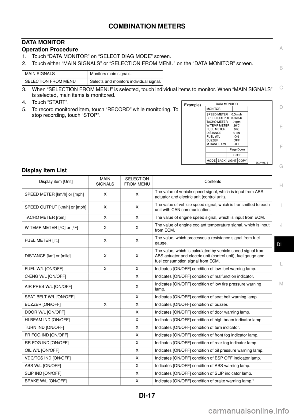
1. Touch “DATA MONITOR” on “SELECT DIAG MODE” screen.
2. Touch either “MAIN SIGNALS” or “SELECTION FROM MENU” on the “DATA MONITOR” screen.
3. When “SELECTION FROM MENU” is selected, touch individual items to monitor. When “MAIN SIGNALS”
is selected, main items is monitored.
4. Touch “START”.
5. To record monitored item, touch “RECORD” while monitoring. To
stop recording, touch “STOP”.
Display Item List
MAIN SIGNALS Monitors main signals.
SELECTION FROM MENU Selects and monitors individual signal.
SKIA4957E
Display item [Unit]MAIN
SIGNALSSELECTION
FROM MENUContents
SPEED METER [km/h] or [mph] X XThe value of vehicle speed signal, which is input from ABS
actuator and electric unit (control unit).
SPEED OUTPUT [km/h] or [mph] X XThe value of vehicle speed signal, which is transmitted to each
unit with CAN communication.
TACHO METER [rpm] X X The value of engine speed signal, which is input from ECM.
W TEMP METER [°C] or [°F] X XThe value of engine coolant temperature signal, which is input
from ECM.
FUEL METER [lit.] X XThe value, which processes a resistance signal from fuel
gauge.
DISTANCE [km] or [mile] X XThe value, which is calculated by vehicle speed signal from
ABS actuator and electric unit (control unit), fuel gauge and
fuel consumption signal from ECM.
FUEL W/L [ON/OFF] X X Indicates [ON/OFF] condition of low-fuel warning lamp.
C-ENG W/L [ON/OFF] X Indicates [ON/OFF] condition of malfunction indicator.
AIR PRES W/L [ON/OFF] XIndicates [ON/OFF] condition of low tire pressure warning
lamp.
SEAT BELT W/L [ON/OFF] X Indicates [ON/OFF] condition of seat belt warning lamp.
BUZZER [ON/OFF] X X Indicates [ON/OFF] condition of buzzer.
DOOR W/L [ON/OFF] X Indicates [ON/OFF] condition of door warning lamp.
HI-BEAM IND [ON/OFF] X Indicates [ON/OFF] condition of high beam indicator lamp.
TURN IND [ON/OFF] X Indicates [ON/OFF] condition of turn indicator.
FR FOG IND [ON/OFF] X Indicates [ON/OFF] condition of front fog indicator lamp.
RR FOG IND [ON/OFF] X Indicates [ON/OFF] condition of rear fog indicator lamp.
OIL W/L [ON/OFF] X Indicates [ON/OFF] condition of oil pressure warning lamp.
VDC/TCS IND [ON/OFF] X Indicates [ON/OFF] condition of ESP OFF indicator lamp.
ABS W/L [ON/OFF] X Indicates [ON/OFF] condition of ABS warning lamp.
SLIP IND [ON/OFF] X Indicates [ON/OFF] condition of SLIP indicator lamp.
BRAKE W/L [ON/OFF] X Indicates [ON/OFF] condition of brake warning lamp.*
Page 968 of 3171
DI-58
WARNING CHIME
CONSULT-II Function (BCM)
EKS00L9K
CONSULT-II can display each diagnostic item using the diagnostic test modes shown following.
DIAGNOSTIC ITEMS DESCRIPTION
CONSULT-II BASIC OPERATION PROCEDURE
CAUTION:
If CONSULT-II is used with no connection of CONSULT-II CONVERTER, malfunctions might be
detected in self-diagnosis depending on control unit which carry out CAN communication.
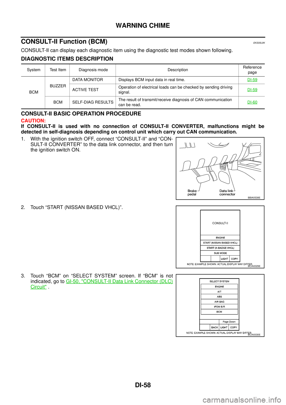
1. With the ignition switch OFF, connect “CONSULT-II” and “CON-
SULT-II CONVERTER” to the data link connector, and then turn
the ignition switch ON.
2. Touch “START (NISSAN BASED VHCL)”.
3. Touch “BCM” on “SELECT SYSTEM” screen. If “BCM” is not
indicated, go toGI-50, "
CONSULT-II Data Link Connector (DLC)
Circuit".
System Test Item Diagnosis mode DescriptionReference
page
BCMBUZZERDATA MONITOR Displays BCM input data in real time.DI-59
ACTIVE TESTOperation of electrical loads can be checked by sending driving
signal.DI-59
BCM SELF-DIAG RESULTSThe result of transmit/receive diagnosis of CAN communication
canberead.DI-60
BBIA0538E
BCIA0029E
BCIA0030E
Page 1003 of 3171
BASIC SERVICE PROCEDURE
EC-23
C
D
E
F
G
H
I
J
K
L
MA
EC
BASIC SERVICE PROCEDUREPFP:00018
Fuel FilterEBS01KCK
DESCRIPTION
A water draining cock is on the lower side and a priming pump for bleeding air is on the upper side.
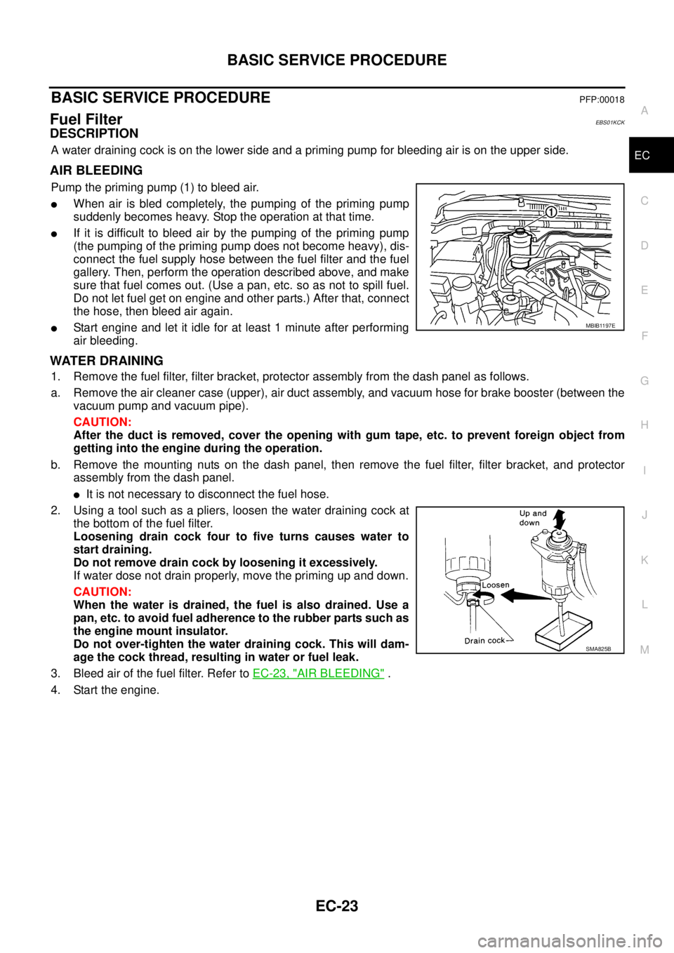
AIR BLEEDING
Pump the priming pump (1) to bleed air.
lWhen air is bled completely, the pumping of the priming pump
suddenly becomes heavy. Stop the operation at that time.
lIf it is difficult to bleed air by the pumping of the priming pump
(the pumping of the priming pump does not become heavy), dis-
connect the fuel supply hose between the fuel filter and the fuel
gallery. Then, perform the operation described above, and make
sure that fuel comes out. (Use a pan, etc. so as not to spill fuel.
Do not let fuel get on engine and other parts.) After that, connect
the hose, then bleed air again.
lStart engine and let it idle for at least 1 minute after performing
air bleeding.
WATER DRAINING
1. Remove the fuel filter, filter bracket, protector assembly from the dash panel as follows.
a. Remove the air cleaner case (upper), air duct assembly, and vacuum hose for brake booster (between the
vacuum pump and vacuum pipe).
CAUTION:
After the duct is removed, cover the opening with gum tape, etc. to prevent foreign object from
getting into the engine during the operation.
b. Remove the mounting nuts on the dash panel, then remove the fuel filter, filter bracket, and protector
assembly from the dash panel.
lIt is not necessary to disconnect the fuel hose.
2. Using a tool such as a pliers, loosen the water draining cock at
the bottom of the fuel filter.
Loosening drain cock four to five turns causes water to
start draining.
Do not remove drain cock by loosening it excessively.
If water dose not drain properly, move the priming up and down.
CAUTION:
When the water is drained, the fuel is also drained. Use a
pan, etc. to avoid fuel adherence to the rubber parts such as
the engine mount insulator.
Do not over-tighten the water draining cock. This will dam-
age the cock thread, resulting in water or fuel leak.
3. Bleed air of the fuel filter. Refer toEC-23, "
AIR BLEEDING".
4. Start the engine.
MBIB1197E
SMA825B
Page 1005 of 3171
BASIC SERVICE PROCEDURE
EC-25
C
D
E
F
G
H
I
J
K
L
MA
EC
Injector Adjustment Value RegistrationEBS01KCM
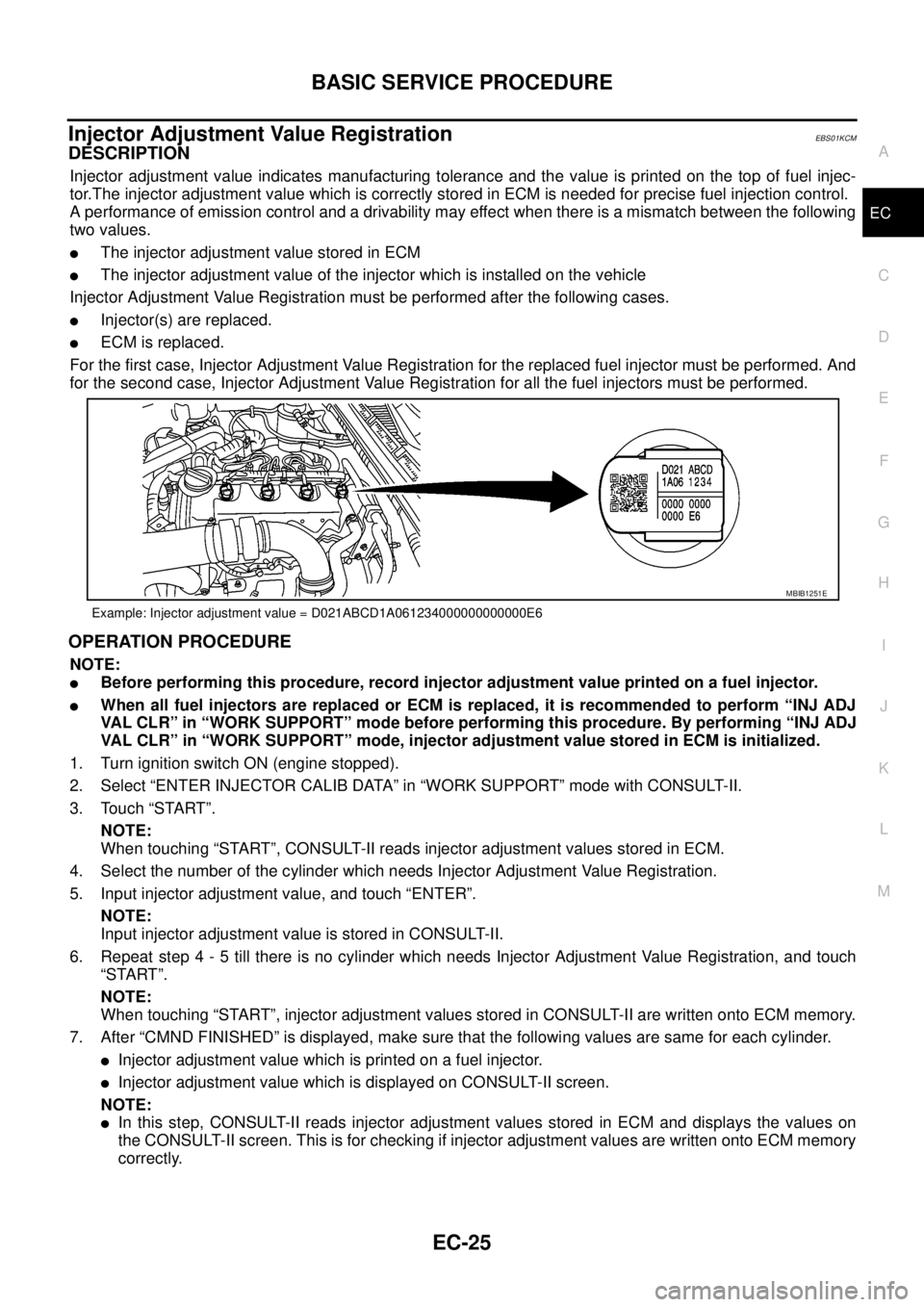
DESCRIPTION
Injector adjustment value indicates manufacturing tolerance and the value is printed on the top of fuel injec-
tor.The injector adjustment value which is correctly stored in ECM is needed for precise fuel injection control.
A performance of emission control and a drivability may effect when there is a mismatch between the following
two values.
lThe injector adjustment value stored in ECM
lThe injector adjustment value of the injector which is installed on the vehicle
Injector Adjustment Value Registration must be performed after the following cases.
lInjector(s) are replaced.
lECM is replaced.
For the first case, Injector Adjustment Value Registration for the replaced fuel injector must be performed. And
for the second case, Injector Adjustment Value Registration for all the fuel injectors must be performed.
OPERATION PROCEDURE
NOTE:
lBefore performing this procedure, record injector adjustment value printed on a fuel injector.
lWhen all fuel injectors are replaced or ECM is replaced, it is recommended to perform “INJ ADJ
VAL CLR” in “WORK SUPPORT” mode before performing this procedure. By performing “INJ ADJ
VAL CLR” in “WORK SUPPORT” mode, injector adjustment value stored in ECM is initialized.
1. Turn ignition switch ON (engine stopped).
2. Select “ENTER INJECTOR CALIB DATA” in “WORK SUPPORT” mode with CONSULT-II.
3. Touch “START”.
NOTE:
When touching “START”, CONSULT-II reads injector adjustment values stored in ECM.
4. Select the number of the cylinder which needs Injector Adjustment Value Registration.
5. Input injector adjustment value, and touch “ENTER”.
NOTE:
Input injector adjustment value is stored in CONSULT-II.
6. Repeat step 4 - 5 till there is no cylinder which needs Injector Adjustment Value Registration, and touch
“START”.
NOTE:
When touching “START”, injector adjustment values stored in CONSULT-II are written onto ECM memory.
7. After “CMND FINISHED” is displayed, make sure that the following values are same for each cylinder.
lInjector adjustment value which is printed on a fuel injector.
lInjector adjustment value which is displayed on CONSULT-II screen.
NOTE:
lIn this step, CONSULT-II reads injector adjustment values stored in ECM and displays the values on
the CONSULT-II screen. This is for checking if injector adjustment values are written onto ECM memory
correctly.
Example: Injector adjustment value = D021ABCD1A061234000000000000E6
MBIB1251E
Page 1009 of 3171
ON BOARD DIAGNOSTIC (OBD) SYSTEM
EC-29
C
D
E
F
G
H
I
J
K
L
MA
EC
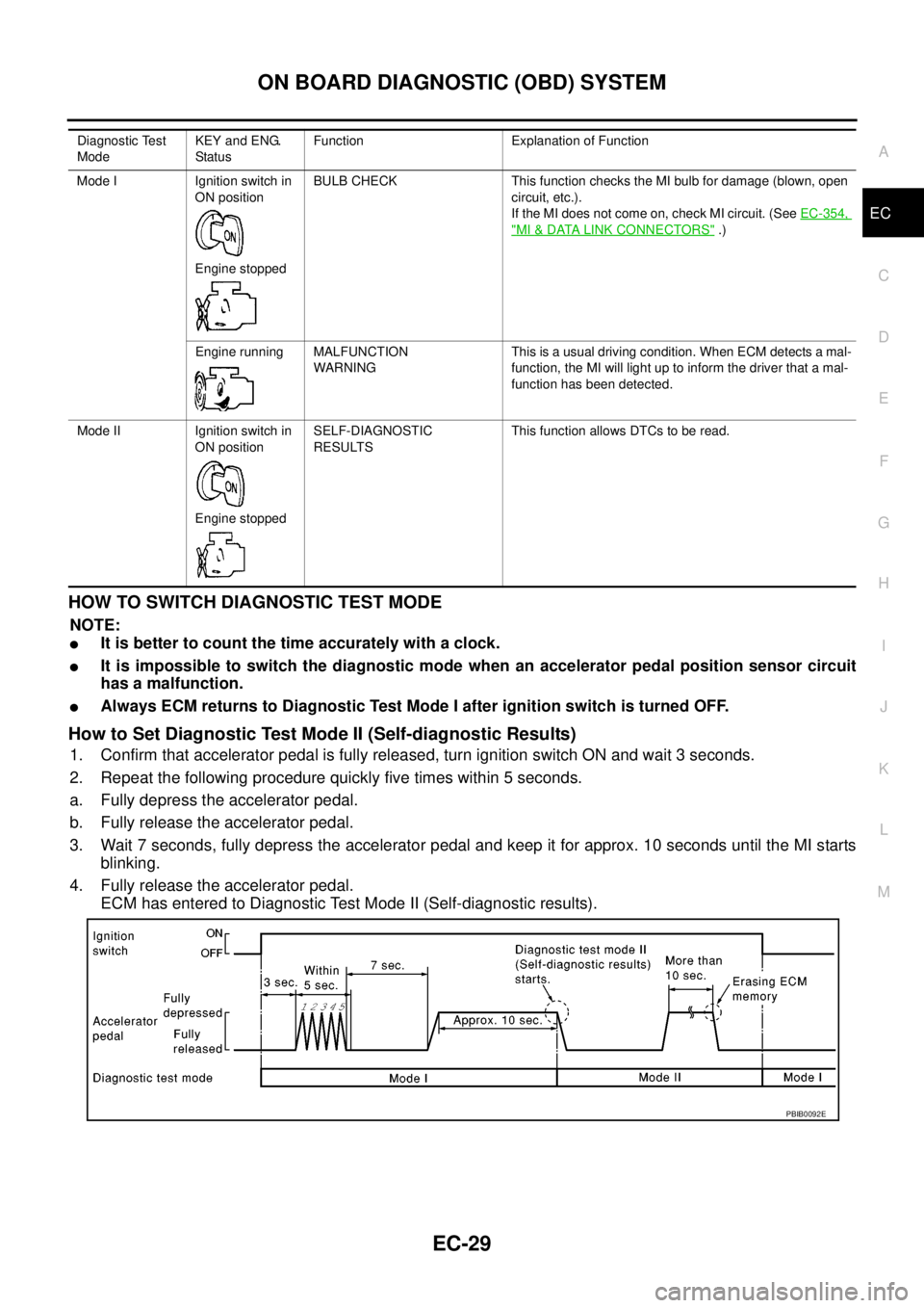
HOWTOSWITCHDIAGNOSTICTESTMODE
NOTE:
lIt is better to count the time accurately with a clock.
lIt is impossible to switch the diagnostic mode when an accelerator pedal position sensor circuit
has a malfunction.
lAlways ECM returns to Diagnostic Test Mode I after ignition switch is turned OFF.
How to Set Diagnostic Test Mode II (Self-diagnostic Results)
1. Confirm that accelerator pedal is fully released, turn ignition switch ON and wait 3 seconds.
2. Repeat the following procedure quickly five times within 5 seconds.
a. Fully depress the accelerator pedal.
b. Fully release the accelerator pedal.
3. Wait 7 seconds, fully depress the accelerator pedal and keep it for approx. 10 seconds until the MI starts
blinking.
4. Fully release the accelerator pedal.
ECM has entered to Diagnostic Test Mode II (Self-diagnostic results).
Diagnostic Test
ModeKEY and ENG.
Statu sFunction Explanation of Function
Mode I Ignition switch in
ON position
Engine stoppedBULB CHECK This function checks the MI bulb for damage (blown, open
circuit, etc.).
If the MI does not come on, check MI circuit. (SeeEC-354,
"MI&DATA LINK CONNECTORS".)
Engine running MALFUNCTION
WARNINGThis is a usual driving condition. When ECM detects a mal-
function, the MI will light up to inform the driver that a mal-
function has been detected.
Mode II Ignition switch in
ON position
Engine stoppedSELF-DIAGNOSTIC
RESULTSThis function allows DTCs to be read.
PBIB0092E