Neutral position NISSAN NAVARA 2005 Repair Repair Manual
[x] Cancel search | Manufacturer: NISSAN, Model Year: 2005, Model line: NAVARA, Model: NISSAN NAVARA 2005Pages: 3171, PDF Size: 49.59 MB
Page 2636 of 3171
STEERING WHEEL
PS-9
C
D
E
F
H
I
J
K
L
MA
B
PS
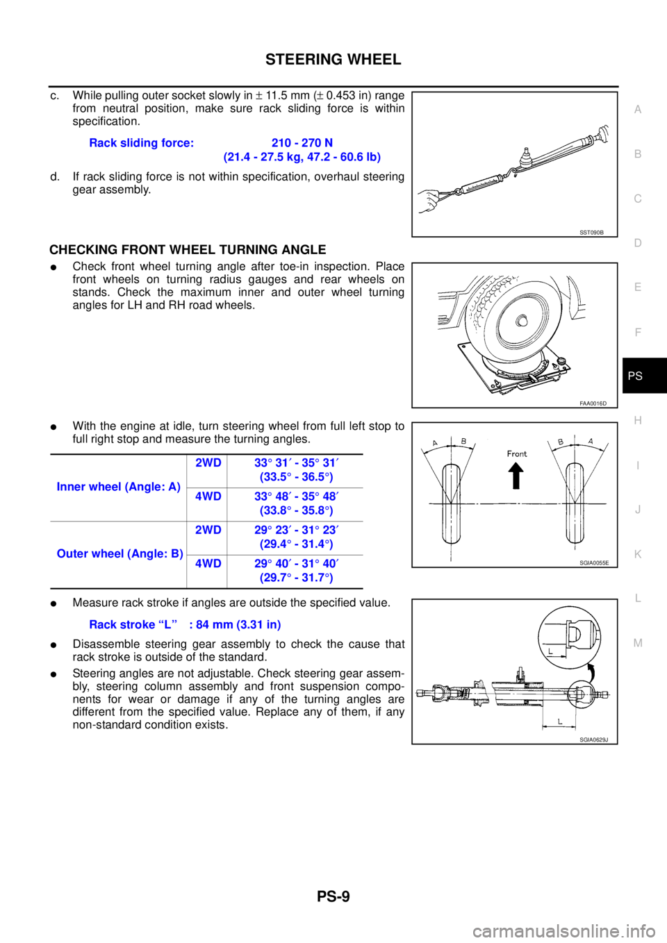
c. While pulling outer socket slowly in±11 . 5 m m (±0.453 in) range
from neutral position, make sure rack sliding force is within
specification.
d. If rack sliding force is not within specification, overhaul steering
gear assembly.
CHECKING FRONT WHEEL TURNING ANGLE
lCheck front wheel turning angle after toe-in inspection. Place
front wheels on turning radius gauges and rear wheels on
stands. Check the maximum inner and outer wheel turning
angles for LH and RH road wheels.
lWith the engine at idle, turn steering wheel from full left stop to
full right stop and measure the turning angles.
lMeasure rack stroke if angles are outside the specified value.
lDisassemble steering gear assembly to check the cause that
rack stroke is outside of the standard.
lSteering angles are not adjustable. Check steering gear assem-
bly, steering column assembly and front suspension compo-
nents for wear or damage if any of the turning angles are
different from the specified value. Replace any of them, if any
non-standard condition exists.Rack sliding force: 210 - 270 N
(21.4 - 27.5 kg, 47.2 - 60.6 lb)
SST090B
FAA0016D
Inner wheel (Angle: A)2WD 33°31¢-35°31¢
(33.5°-36.5°)
4WD 33°48¢-35°48¢
(33.8°-35.8°)
Outer wheel (Angle: B)2WD 29°23¢-31°23¢
(29.4°-31.4°)
4WD 29°40¢-31°40¢
(29.7°-31.7°)
SGIA0055E
Rack stroke “L” : 84 mm (3.31 in)
SGIA0629J
Page 2637 of 3171
PS-10
STEERING WHEEL
Removal and Installation
EGS001LH
REMOVAL
NOTE:
When reconnecting spiral cable, fix cable with a tape so that fixing case and rotating part keep aligned. This
will omit neutral position alignment procedure during spiral installation.
1. Set vehicle to the straight-ahead position.
2. Remove driver air bag module. Refer toSRS-36, "
DRIVER AIR BAG MODULE".
3. Remove steering wheel lock nut after steering is locked.
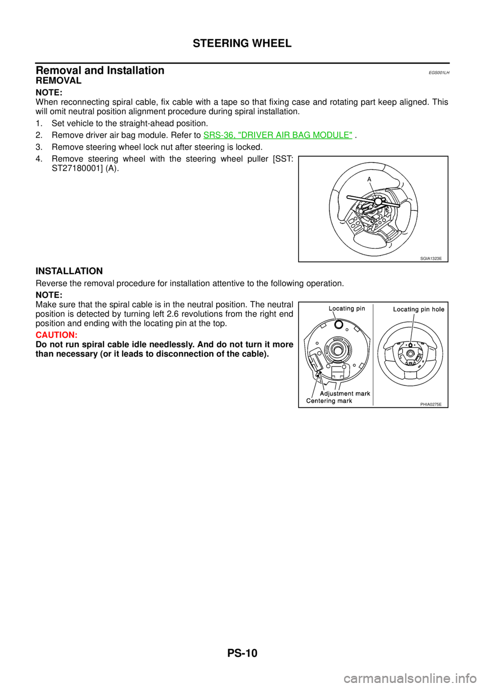
4. Remove steering wheel with the steering wheel puller [SST:
ST27180001] (A).
INSTALLATION
Reverse the removal procedure for installation attentive to the following operation.
NOTE:
Make sure that the spiral cable is in the neutral position. The neutral
position is detected by turning left 2.6 revolutions from the right end
position and ending with the locating pin at the top.
CAUTION:
Do not run spiral cable idle needlessly. And do not turn it more
than necessary (or it leads to disconnection of the cable).
SGIA1323E
PHIA0275E
Page 2639 of 3171
PS-12
STEERING COLUMN
9. Remove steering column assembly mounting nuts, and then remove steering column assembly from vehi-
cle.
10. Remove fixing bolt and nut of upper joint (lower side), and then remove upper joint and collar from upper
shaft.
11. Loosen clamp, and then remove hole cover seal from hole cover.
12. Remove mounting nuts of hole cover, and then remove clamp, hole cover mounting plate and hole cover
from dash panel.
13. Raise vehicle.
14. Remove fixing bolt of lower shaft (lower side), and then remove lower shaft and upper shaft from vehicle.
INSPECTION AFTER REMOVAL
lCheck component parts for damage or other malfunctions. Replace if there are.
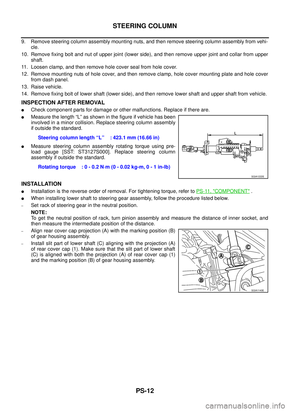
lMeasure the length “L” as shown in the figure if vehicle has been
involved in a minor collision. Replace steering column assembly
if outside the standard.
lMeasure steering column assembly rotating torque using pre-
load gauge [SST: ST3127S000]. Replace steering column
assembly if outside the standard.
INSTALLATION
lInstallation is the reverse order of removal. For tightening torque, refer toPS-11, "COMPONENT".
lWhen installing lower shaft to steering gear assembly, follow the procedure listed below.
–Set rack of steering gear in the neutral position.
NOTE:
To get the neutral position of rack, turn pinion assembly and measure the distance of inner socket, and
then measure the intermediate position of the distance.
–Align rear cover cap projection (A) with the marking position (B)
of gear housing assembly.
–Install slit part of lower shaft (C) aligning with the projection (A)
of rear cover cap (1). Make sure that the slit part of lower shaft
(C) is aligned with both the projection (A) of rear cover cap (1)
and the marking position (B) of gear housing assembly.Steering column length “L” : 423.1 mm (16.66 in)
Rotating torque : 0 - 0.2 N·m (0 - 0.02 kg-m, 0 - 1 in-lb)
SGIA1222E
SGIA1140E
Page 2642 of 3171
POWER STEERING GEAR AND LINKAGE
PS-15
C
D
E
F
H
I
J
K
L
MA
B
PS
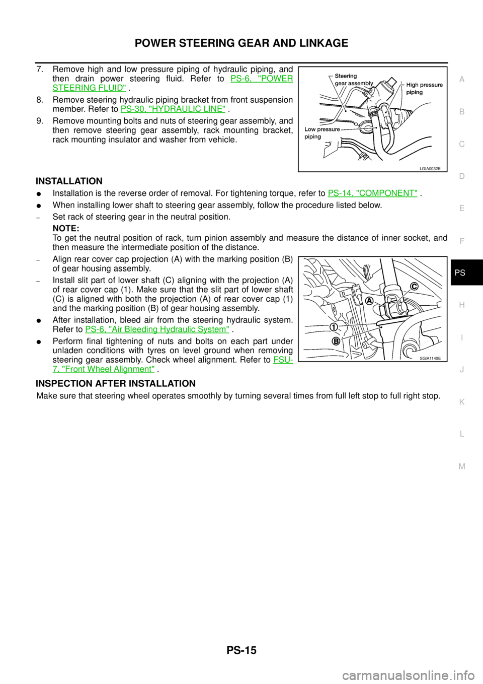
7. Remove high and low pressure piping of hydraulic piping, and
then drain power steering fluid. Refer toPS-6, "
POWER
STEERING FLUID".
8. Remove steering hydraulic piping bracket from front suspension
member. Refer toPS-30, "
HYDRAULIC LINE".
9. Remove mounting bolts and nuts of steering gear assembly, and
then remove steering gear assembly, rack mounting bracket,
rack mounting insulator and washer from vehicle.
INSTALLATION
lInstallation is the reverse order of removal. For tightening torque, refer toPS-14, "COMPONENT".
lWhen installing lower shaft to steering gear assembly, follow the procedure listed below.
–Set rack of steering gear in the neutral position.
NOTE:
To get the neutral position of rack, turn pinion assembly and measure the distance of inner socket, and
then measure the intermediate position of the distance.
–Align rear cover cap projection (A) with the marking position (B)
of gear housing assembly.
–Install slit part of lower shaft (C) aligning with the projection (A)
of rear cover cap (1). Make sure that the slit part of lower shaft
(C) is aligned with both the projection (A) of rear cover cap (1)
and the marking position (B) of gear housing assembly.
lAfter installation, bleed air from the steering hydraulic system.
Refer toPS-6, "
Air Bleeding Hydraulic System".
lPerform final tightening of nuts and bolts on each part under
unladen conditions with tyres on level ground when removing
steering gear assembly. Check wheel alignment. Refer toFSU-
7, "Front Wheel Alignment".
INSPECTION AFTER INSTALLATION
Make sure that steering wheel operates smoothly by turning several times from full left stop to full right stop.
LGIA0032E
SGIA1140E
Page 2649 of 3171
PS-22
POWER STEERING GEAR AND LINKAGE
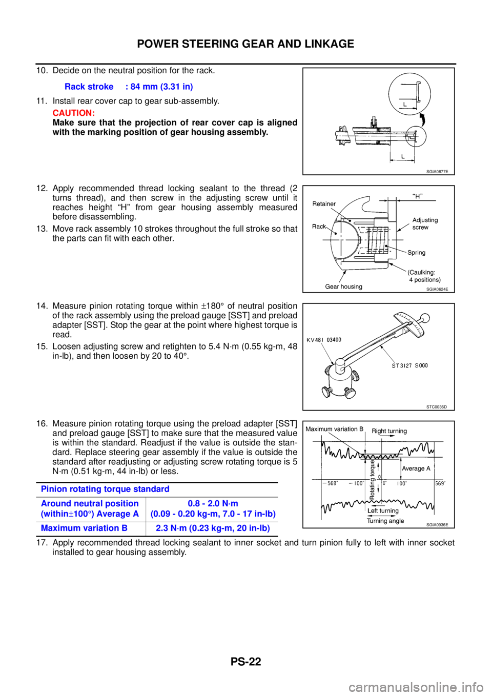
10. Decide on the neutral position for the rack.
11. Install rear cover cap to gear sub-assembly.
CAUTION:
Make sure that the projection of rear cover cap is aligned
with the marking position of gear housing assembly.
12. Apply recommended thread locking sealant to the thread (2
turns thread), and then screw in the adjusting screw until it
reaches height “H” from gear housing assembly measured
before disassembling.
13. Move rack assembly 10 strokes throughout the full stroke so that
the parts can fit with each other.
14. Measure pinion rotating torque within±180°of neutral position
of the rack assembly using the preload gauge [SST] and preload
adapter [SST]. Stop the gear at the point where highest torque is
read.
15. Loosen adjusting screw and retighten to 5.4 N·m (0.55 kg-m, 48
in-lb), and then loosen by 20 to 40°.
16. Measure pinion rotating torque using the preload adapter [SST]
and preload gauge [SST] to make sure that the measured value
is within the standard. Readjust if the value is outside the stan-
dard. Replace steering gear assembly if the value is outside the
standard after readjusting or adjusting screw rotating torque is 5
N·m (0.51 kg-m, 44 in-lb) or less.
17. Apply recommended thread locking sealant to inner socket and turn pinion fully to left with inner socket
installed to gear housing assembly.Rack stroke : 84 mm (3.31 in)
SGIA0877E
SGIA0624E
STC0036D
Pinion rotating torque standard
Around neutral position
(within±100°)AverageA0.8 - 2.0 N·m
(0.09 - 0.20 kg-m, 7.0 - 17 in-lb)
Maximum variation B 2.3 N·m (0.23 kg-m, 20 in-lb)
SGIA0936E
Page 2662 of 3171
SERVICE DATA AND SPECIFICATIONS (SDS)
PS-35
C
D
E
F
H
I
J
K
L
MA
B
PS
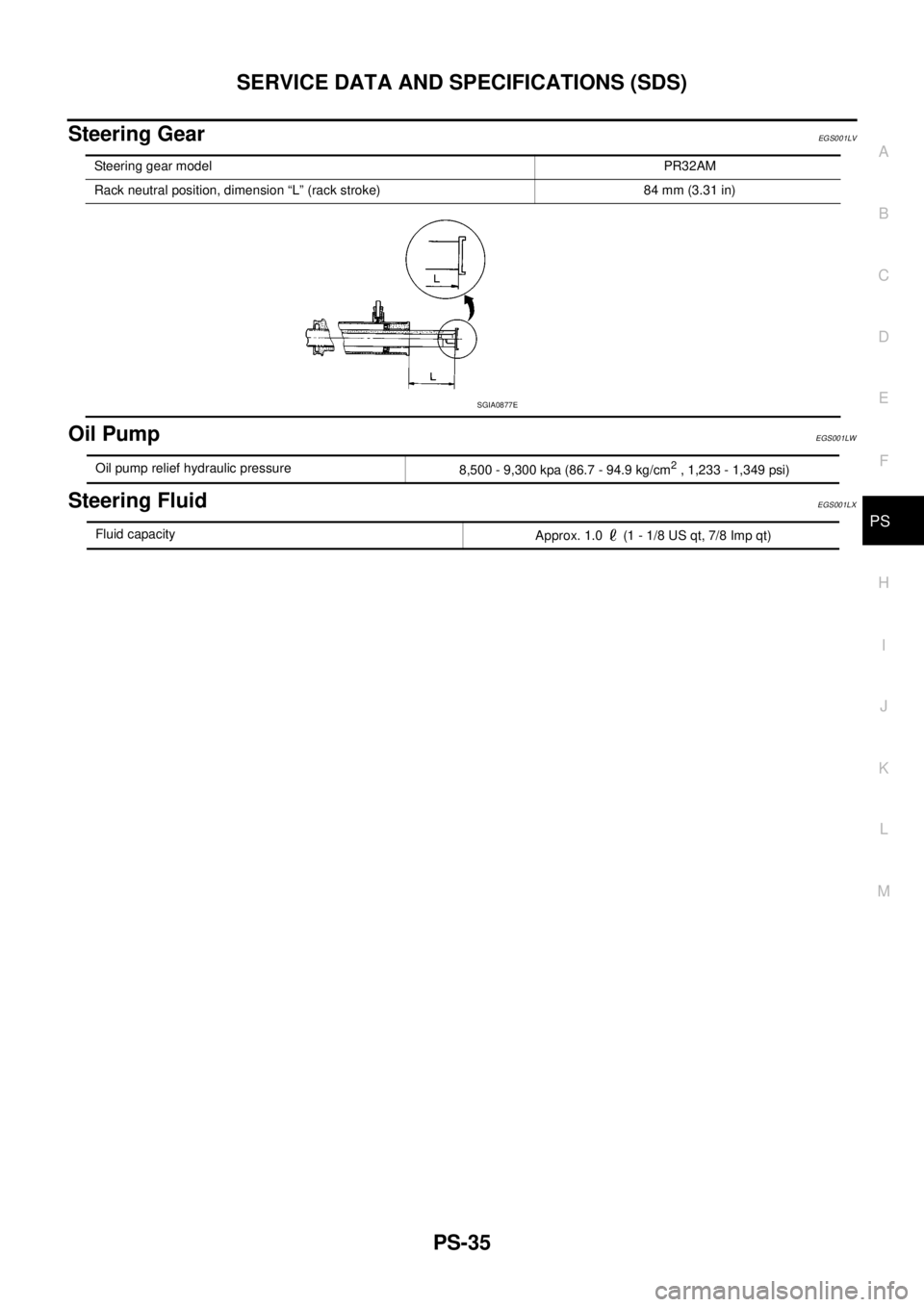
Steering GearEGS001LV
Oil PumpEGS001LW
Steering FluidEGS001LX
Steering gear modelPR32AM
Rack neutral position, dimension “L” (rack stroke) 84 mm (3.31 in)
SGIA0877E
Oil pump relief hydraulic pressure
8,500 - 9,300 kpa (86.7 - 94.9 kg/cm2, 1,233 - 1,349 psi)
Fluid capacity
Approx. 1.0 (1 - 1/8 US qt, 7/8 Imp qt)
Page 2912 of 3171
PRECAUTIONS
SRS-3
C
D
E
F
G
I
J
K
L
MA
B
SRS
PRECAUTIONSPFP:00001
Precautions for Supplemental Restraint System (SRS) “AIR BAG” and “SEAT
BELT PRE-TENSIONER”
EHS001Y8
The Supplemental Restraint System such as “AIR BAG” and “SEAT BELT PRE-TENSIONER”, used along
with a front seat belt, helps to reduce the risk or severity of injury to the driver and front passenger for certain
types of collision. Information necessary to service the system safely is included in the SRS and SB section of
this Service Manual.
WARNING:
lTo avoid rendering the SRS inoperative, which could increase the risk of personal injury or death
in the event of a collision which would result in air bag inflation, all maintenance must be per-
formed by an authorized NISSAN/INFINITI dealer.
lImproper maintenance, including incorrect removal and installation of the SRS, can lead to per-
sonal injury caused by unintentional activation of the system. For removal of Spiral Cable and Air
Bag Module, see the SRS section.
lDo not use electrical test equipment on any circuit related to the SRS unless instructed to in this
Service Manual. SRS wiring harnesses can be identified by yellow and/or orange harnesses or
harness connectors.
Precautions for SRS “AIR BAG” and “SEAT BELT PRE-TENSIONER” ServiceEHS001Y9
lDo not use electrical test equipment to check SRS circuits unless instructed to in this Service Manual.
lBefore servicing the SRS, turn ignition switch OFF, disconnect both battery cables and wait at least 3 min-
utes.
For approximately 3 minutes after the cables are removed, it is still possible for the air bag and seat belt
pre-tensioner to deploy. Therefore, do not work on any SRS connectors or wires until at least 3 minutes
have passed.
lDiagnosis sensor unit must always be installed with their arrow marks “Ü” pointing towards the front of the
vehicle for proper operation. Also check diagnosis sensor unit for cracks, deformities or rust before instal-
lation and replace as required.
lThe spiral cable must be aligned with the neutral position since its rotations are limited. Do not attempt to
turn steering wheel or column after removal of steering gear.
lHandle air bag module carefully. Always place driver and front passenger air bag modules with the pad
side facing upward and place front side air bag module standing with stud bolt side setting bottom.
lConduct self-diagnosis to check entire SRS for proper function after replacing any components.
lAfter air bag inflates, the front instrument panel assembly should be replaced if damaged.
lAlways replace instrument panel pad following front passenger air bag deployment.
Precautions for Trouble DiagnosisEHS001YA
When you read wiring diagrams, refer to the following:
lGI-15, "How to Read Wiring Diagrams"in GI section
lPG-4, "POWER SUPPLY ROUTING CIRCUIT"in PG section
When you perform trouble diagnosis, refer to the following:
lGI-11, "How to Follow Trouble Diagnoses"in GI section
lGI-24, "How to Perform Efficient Diagnosis for an Electrical Incident"in GI section
Check for any service bulletins before servicing the vehicle.
Page 2948 of 3171
SPIRAL CABLE
SRS-39
C
D
E
F
G
I
J
K
L
MA
B
SRS
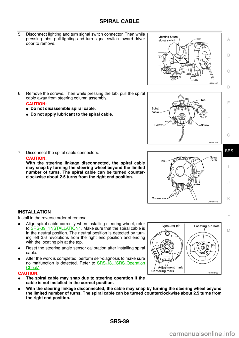
5. Disconnect lighting and turn signal switch connector. Then while
pressing tabs, pull lighting and turn signal switch toward driver
door to remove.
6. Remove the screws. Then while pressing the tab, pull the spiral
cable away from steering column assembly.
CAUTION:
lDo not disassemble spiral cable.
lDo not apply lubricant to the spiral cable.
7. Disconnect the spiral cable connectors.
CAUTION:
With the steering linkage disconnected, the spiral cable
may snap by turning the steering wheel beyond the limited
number of turns. The spiral cable can be turned counter-
clockwise about 2.5 turns from the right end position.
INSTALLATION
Install in the reverse order of removal.
lAlign spiral cable correctly when installing steering wheel, refer
toSRS-39, "
INSTALLATION". Make sure that the spiral cable is
in the neutral position. The neutral position is detected by turn-
ing left 2.6 revolutions from the right end position and ending
with the locating pin at the top.
lReset the steering angle sensor calibration after installing spiral
cable.
lAfter the work is completed, perform self-diagnosis to make sure
no malfunction is detected. Refer toSRS-18, "
SRS Operation
Check".
CAUTION:
lThe spiral cable may snap due to steering operation if the
cable is not installed in the correct position.
lWith the steering linkage disconnected, the cable may snap by turning the steering wheel beyond
the limited number of turns. The spiral cable can be turned counterclockwise about 2.5 turns from
the right end position.
LHIA0035E
LHIA0036E
LHIA0088E
PHIA0275E
Page 2969 of 3171

TF-2
DIAGNOSTIC PROCEDURE .............................. 53
COMPONENT INSPECTION .............................. 54
Transfer Control Unit .............................................. 54
DIAGNOSTIC PROCEDURE .............................. 54
Output Shaft Revolution Signal (TCM) ................... 55
DIAGNOSTIC PROCEDURE .............................. 55
Vehicle Speed Sensor (ABS) .................................. 55
DIAGNOSTIC PROCEDURE .............................. 55
4LO Switch ............................................................. 56
CONSULT-II REFERENCE VALUE IN DATA
MONITOR MODE ................................................ 56
TRANSFER CONTROL UNIT TERMINALS AND
REFERENCE VALUE .......................................... 56
DIAGNOSTIC PROCEDURE .............................. 57
COMPONENT INSPECTION .............................. 59
4WD Shift Switch .................................................... 59
CONSULT-II REFERENCE VALUE IN DATA
MONITOR MODE ................................................ 59
TRANSFER CONTROL UNIT TERMINALS AND
REFERENCE VALUE .......................................... 59
DIAGNOSTIC PROCEDURE .............................. 60
COMPONENT INSPECTION .............................. 62
Wait Detection Switch ............................................. 63
CONSULT-II REFERENCE VALUE IN DATA
MONITOR MODE ................................................ 63
TRANSFER CONTROL UNIT TERMINALS AND
REFERENCE VALUE .......................................... 63
DIAGNOSTIC PROCEDURE .............................. 64
COMPONENT INSPECTION .............................. 66
PNP Switch Signal (TCM) ...................................... 66
DIAGNOSTIC PROCEDURE .............................. 66
Actuator Motor ........................................................ 67
CONSULT-II REFERENCE VALUE IN DATA
MONITOR MODE ................................................ 67
TRANSFER CONTROL UNIT TERMINALS AND
REFERENCE VALUE .......................................... 67
DIAGNOSTIC PROCEDURE .............................. 68
COMPONENT INSPECTION .............................. 74
Actuator Position Switch ......................................... 75
CONSULT-II REFERENCE VALUE IN DATA
MONITOR MODE ................................................ 75
TRANSFER CONTROL UNIT TERMINALS AND
REFERENCE VALUE .......................................... 75
DIAGNOSTIC PROCEDURE .............................. 76
Transfer Control Device .......................................... 78
CONSULT-II REFERENCE VALUE IN DATA
MONITOR MODE ................................................ 78
TRANSFER CONTROL UNIT TERMINALS AND
REFERENCE VALUE .......................................... 78
DIAGNOSTIC PROCEDURE .............................. 79
Engine Speed Signal (ECM) ................................... 81
DIAGNOSTIC PROCEDURE .............................. 81
CAN Communication Line ...................................... 82
DIAGNOSTIC PROCEDURE .............................. 82
ATP Switch ............................................................. 82
CONSULT-II REFERENCE VALUE IN DATA
MONITOR MODE ................................................ 82
TRANSFER CONTROL UNIT TERMINALS ANDREFERENCE VALUE .......................................... 82
DIAGNOSTIC PROCEDURE ............................... 83
COMPONENT INSPECTION ............................... 85
Park/Neutral Position Switch ................................... 85
TRANSFER CONTROL UNIT TERMINALS AND
REFERENCE VALUE .......................................... 85
DIAGNOSTIC PROCEDURE ............................... 85
COMPONENT INSPECTION ............................... 87
TROUBLE DIAGNOSIS FOR SYMPTOMS .............. 88
4WD Shift Indicator Lamp and 4LO Indicator Lamp
Do Not Turn ON ...................................................... 88
SYMPTOM: .......................................................... 88
DIAGNOSTIC PROCEDURE ............................... 89
4WD Warning Lamp Does Not Turn ON ................. 91
SYMPTOM: .......................................................... 91
DIAGNOSTIC PROCEDURE ............................... 92
4WD Shift Indicator Lamp or 4LO Indicator Lamp
Does Not Change ................................................... 94
SYMPTOM: .......................................................... 94
DIAGNOSTIC PROCEDURE ............................... 95
ATP Warning Lamp Does Not Turn ON .................. 96
SYMPTOM: .......................................................... 96
DIAGNOSTIC PROCEDURE ............................... 96
4WD Shift Indicator Lamp Repeats Flashing .......... 98
SYMPTOM: .......................................................... 98
DIAGNOSTIC PROCEDURE ............................... 98
4WD Warning Lamp Flashes Slowly ....................... 99
SYMPTOM: .......................................................... 99
DIAGNOSTIC PROCEDURE ............................... 99
TRANSFER CONTROL UNIT .................................100
Removal and Installation .......................................100
REMOVAL ..........................................................100
INSTALLATION ..................................................100
FRONT OIL SEAL ...................................................101
Removal and Installation .......................................101
REMOVAL ..........................................................101
INSTALLATION ..................................................102
REAR OIL SEAL .....................................................103
Removal and Installation .......................................103
REMOVAL ..........................................................103
INSTALLATION ..................................................103
TRANSFER CONTROL DEVICE ............................105
Removal and Installation .......................................105
REMOVAL ..........................................................105
INSTALLATION ..................................................105
AIR BREATHER HOSE ...........................................107
Removal and Installation .......................................107
A/T MODELS .....................................................107
M/T MODELS .....................................................109
TRANSFER ASSEMBLY ......................................... 111
Removal and Installation ....................................... 111
REMOVAL .......................................................... 111
INSTALLATION ..................................................112
Disassembly and Assembly ..................................112
COMPONENTS .................................................112
DISASSEMBLY ..................................................114
INSPECTION AFTER DISASSEMBLY ..............119
ASSEMBLY ........................................................120
Page 2972 of 3171
PRECAUTIONS
TF-5
C
E
F
G
H
I
J
K
L
MA
B
TF
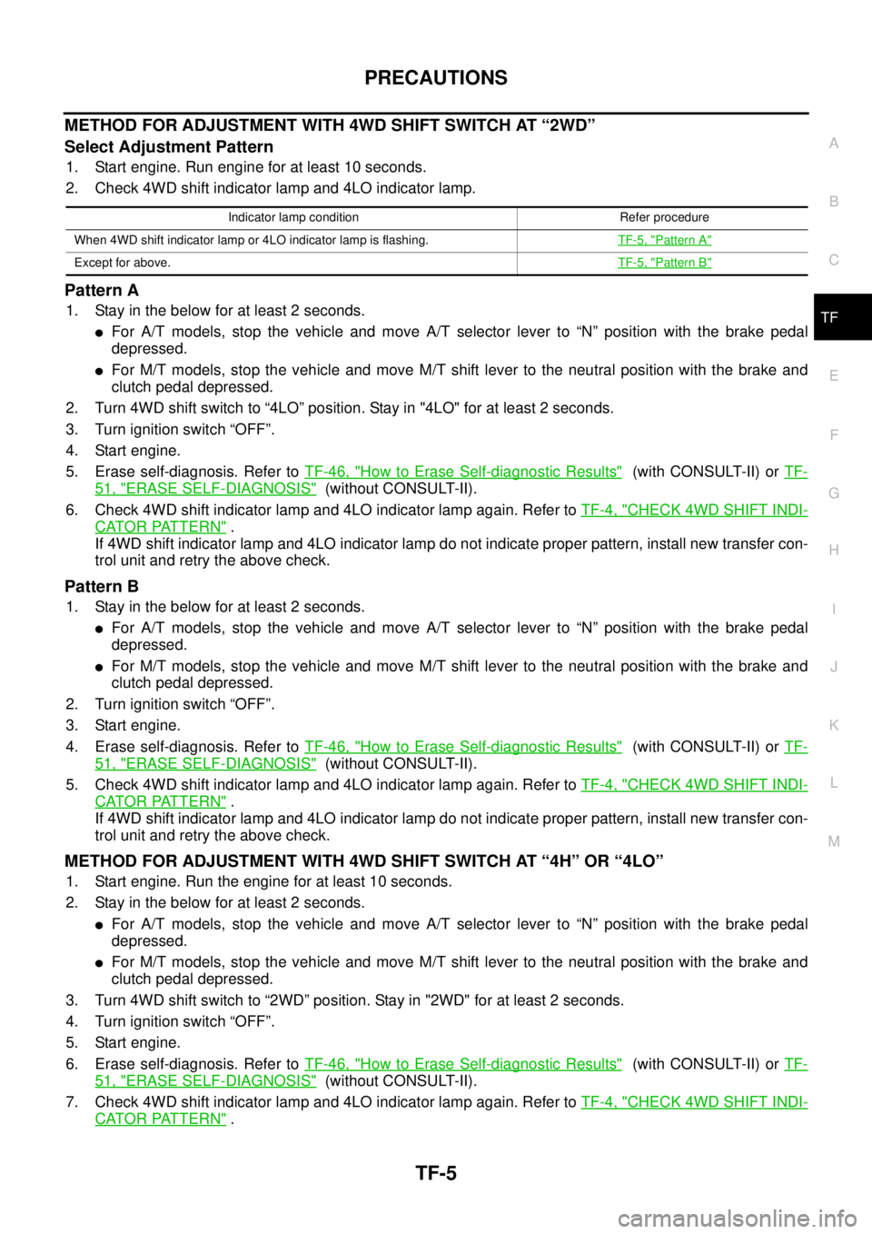
METHODFORADJUSTMENTWITH4WDSHIFTSWITCHAT“2WD”
Select Adjustment Pattern
1. Start engine. Run engine for at least 10 seconds.
2. Check 4WD shift indicator lamp and 4LO indicator lamp.
Pattern A
1. Stay in the below for at least 2 seconds.
lFor A/T models, stop the vehicle and move A/T selector lever to “N” position with the brake pedal
depressed.
lFor M/T models, stop the vehicle and move M/T shift lever to the neutral position with the brake and
clutch pedal depressed.
2. Turn 4WD shift switch to “4LO” position. Stay in "4LO" for at least 2 seconds.
3. Turn ignition switch “OFF”.
4. Start engine.
5. Erase self-diagnosis. Refer toTF-46, "
How to Erase Self-diagnostic Results"(with CONSULT-II) orTF-
51, "ERASE SELF-DIAGNOSIS"(without CONSULT-II).
6. Check 4WD shift indicator lamp and 4LO indicator lamp again. Refer toTF-4, "
CHECK 4WD SHIFT INDI-
CATOR PATTERN".
If 4WD shift indicator lamp and 4LO indicator lamp do not indicate proper pattern, install new transfer con-
trol unit and retry the above check.
Pattern B
1. Stay in the below for at least 2 seconds.
lFor A/T models, stop the vehicle and move A/T selector lever to “N” position with the brake pedal
depressed.
lFor M/T models, stop the vehicle and move M/T shift lever to the neutral position with the brake and
clutch pedal depressed.
2. Turn ignition switch “OFF”.
3. Start engine.
4. Erase self-diagnosis. Refer toTF-46, "
How to Erase Self-diagnostic Results"(with CONSULT-II) orTF-
51, "ERASE SELF-DIAGNOSIS"(without CONSULT-II).
5. Check 4WD shift indicator lamp and 4LO indicator lamp again. Refer toTF-4, "
CHECK 4WD SHIFT INDI-
CATOR PATTERN".
If 4WD shift indicator lamp and 4LO indicator lamp do not indicate proper pattern, install new transfer con-
trol unit and retry the above check.
METHODFORADJUSTMENTWITH4WDSHIFTSWITCHAT“4H”OR“4LO”
1. Start engine. Run the engine for at least 10 seconds.
2. Stay in the below for at least 2 seconds.
lFor A/T models, stop the vehicle and move A/T selector lever to “N” position with the brake pedal
depressed.
lFor M/T models, stop the vehicle and move M/T shift lever to the neutral position with the brake and
clutch pedal depressed.
3. Turn 4WD shift switch to “2WD” position. Stay in "2WD" for at least 2 seconds.
4. Turn ignition switch “OFF”.
5. Start engine.
6. Erase self-diagnosis. Refer toTF-46, "
How to Erase Self-diagnostic Results"(with CONSULT-II) orTF-
51, "ERASE SELF-DIAGNOSIS"(without CONSULT-II).
7. Check 4WD shift indicator lamp and 4LO indicator lamp again. Refer toTF-4, "
CHECK 4WD SHIFT INDI-
CATOR PATTERN".
Indicator lamp condition Refer procedure
When 4WD shift indicator lamp or 4LO indicator lamp is flashing.TF-5, "
Pattern A"
Except for above.TF-5, "Pattern B"