Neutral position NISSAN NAVARA 2005 Repair Service Manual
[x] Cancel search | Manufacturer: NISSAN, Model Year: 2005, Model line: NAVARA, Model: NISSAN NAVARA 2005Pages: 3171, PDF Size: 49.59 MB
Page 2331 of 3171
MT-14
SHIFT CONTROL
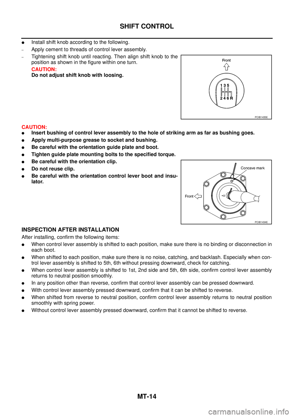
lInstall shift knob according to the following.
–Apply cement to threads of control lever assembly.
–Tightening shift knob until reacting. Then align shift knob to the
position as shown in the figure within one turn.
CAUTION:
Do not adjust shift knob with loosing.
CAUTION:
lInsert bushing of control lever assembly to the hole of striking arm as far as bushing goes.
lApply multi-purpose grease to socket and bushing.
lBe careful with the orientation guide plate and boot.
lTighten guide plate mounting bolts to the specified torque.
lBe careful with the orientation clip.
lDo not reuse clip.
lBe careful with the orientation control lever boot and insu-
lator.
INSPECTION AFTER INSTALLATION
After installing, confirm the following items:
lWhen control lever assembly is shifted to each position, make sure there is no binding or disconnection in
each boot.
lWhen shifted to each position, make sure there is no noise, catching, and backlash. Especially when con-
trol lever assembly is shifted to 5th, 6th without pressing downward, check for catching.
lWhen control lever assembly is shifted to 1st, 2nd side and 5th, 6th side, confirm control lever assembly
returns to neutral position smoothly.
lIn any position other than reverse, confirm that control lever assembly can be pressed downward.
lWith control lever assembly pressed downward, confirm that it can be shifted to reverse.
lWhen shifted from reverse to neutral position, confirm control lever assembly returns to neutral position
smoothly with spring power.
lWithout control lever assembly pressed downward, confirm that it cannot be shifted to reverse.
PCIB1435E
PCIB1434E
Page 2335 of 3171
MT-18
TRANSMISSION ASSEMBLY
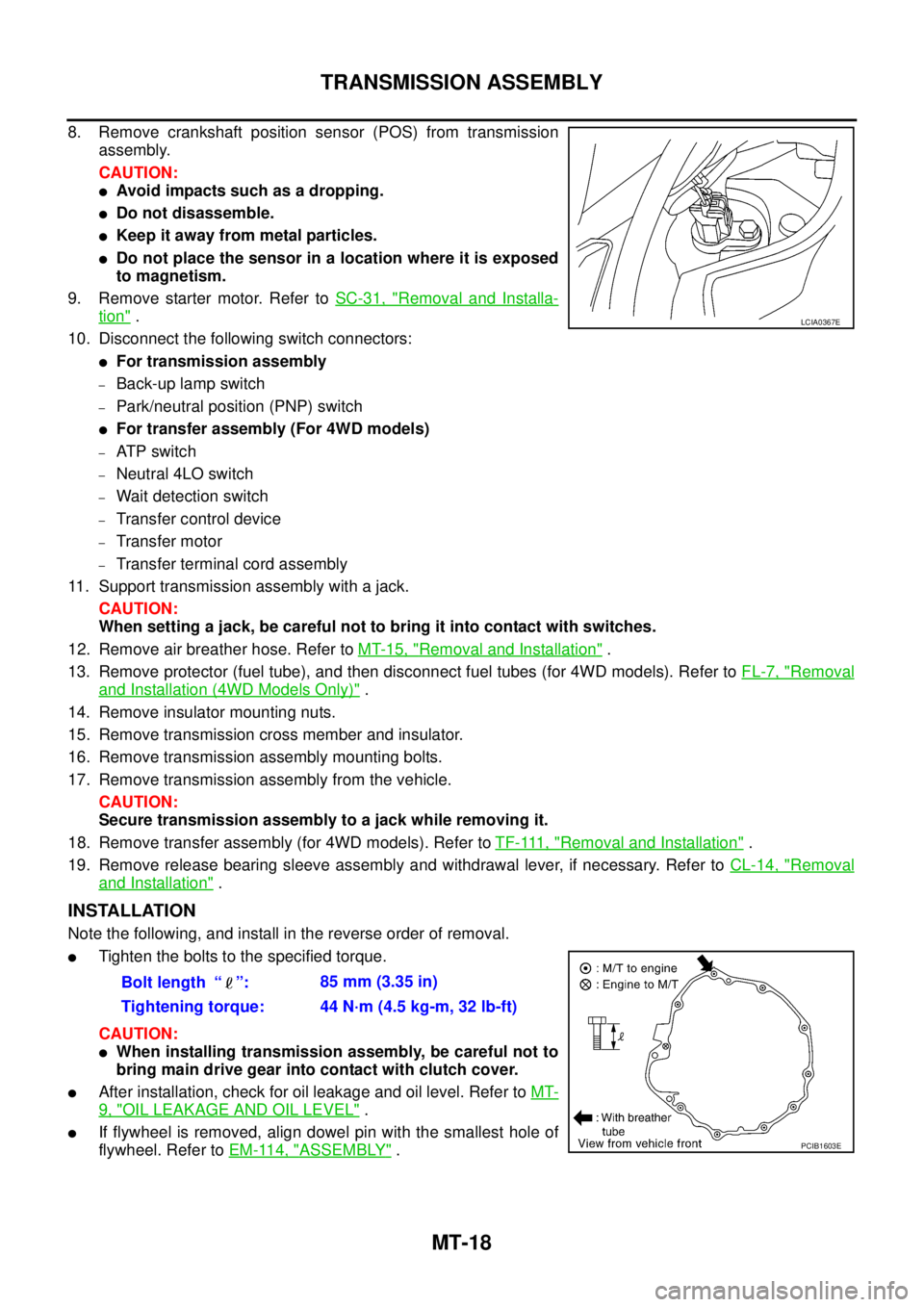
8. Remove crankshaft position sensor (POS) from transmission
assembly.
CAUTION:
lAvoid impacts such as a dropping.
lDo not disassemble.
lKeep it away from metal particles.
lDo not place the sensor in a location where it is exposed
to magnetism.
9. Remove starter motor. Refer toSC-31, "
Removal and Installa-
tion".
10. Disconnect the following switch connectors:
lFor transmission assembly
–Back-up lamp switch
–Park/neutral position (PNP) switch
lFor transfer assembly (For 4WD models)
–AT P s w i t c h
–Neutral 4LO switch
–Wait detection switch
–Transfer control device
–Transfer motor
–Transfer terminal cord assembly
11. Support transmission assembly with a jack.
CAUTION:
When setting a jack, be careful not to bring it into contact with switches.
12. Remove air breather hose. Refer toMT-15, "
Removal and Installation".
13. Remove protector (fuel tube), and then disconnect fuel tubes (for 4WD models). Refer toFL-7, "
Removal
and Installation (4WD Models Only)".
14. Remove insulator mounting nuts.
15. Remove transmission cross member and insulator.
16. Remove transmission assembly mounting bolts.
17. Remove transmission assembly from the vehicle.
CAUTION:
Secure transmission assembly to a jack while removing it.
18. Remove transfer assembly (for 4WD models). Refer toTF-111, "
Removal and Installation".
19. Remove release bearing sleeve assembly and withdrawal lever, if necessary. Refer toCL-14, "
Removal
and Installation".
INSTALLATION
Note the following, and install in the reverse order of removal.
lTighten the bolts to the specified torque.
CAUTION:
lWhen installing transmission assembly, be careful not to
bring main drive gear into contact with clutch cover.
lAfter installation, check for oil leakage and oil level. Refer toMT-
9, "OIL LEAKAGE AND OIL LEVEL".
lIf flywheel is removed, align dowel pin with the smallest hole of
flywheel. Refer toEM-114, "
ASSEMBLY".
LCIA0367E
Bolt length “ ”:85 mm (3.35 in)
Tightening torque: 44 N·m (4.5 kg-m, 32 lb-ft)
PCIB1603E
Page 2337 of 3171
MT-20
TRANSMISSION ASSEMBLY
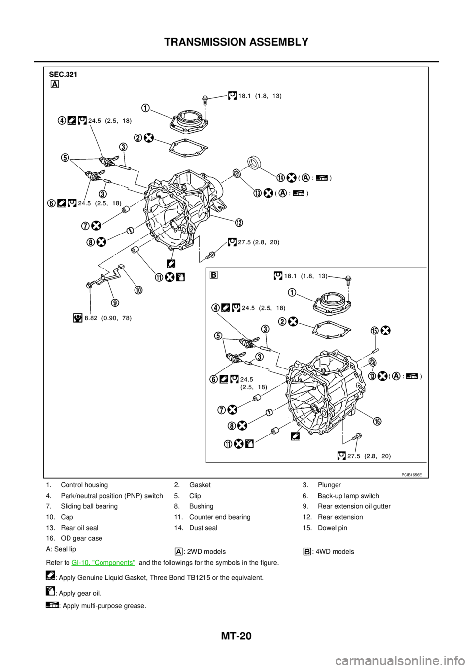
1. Control housing 2. Gasket 3. Plunger
4. Park/neutral position (PNP) switch 5. Clip 6. Back-up lamp switch
7. Sliding ball bearing 8. Bushing 9. Rear extension oil gutter
10. Cap 11. Counter end bearing 12. Rear extension
13. Rear oil seal 14. Dust seal 15. Dowel pin
16. OD gear case
A: Seal lip
: 2WD models : 4WD models
Refer toGI-10, "
Components"and the followings for the symbols in the figure.
: Apply Genuine Liquid Gasket, Three Bond TB1215 or the equivalent.
: Apply gear oil.
: Apply multi-purpose grease.
PCIB1656E
Page 2342 of 3171
TRANSMISSION ASSEMBLY
MT-25
D
E
F
G
H
I
J
K
L
MA
B
MT
DISASSEMBLY
Case Components
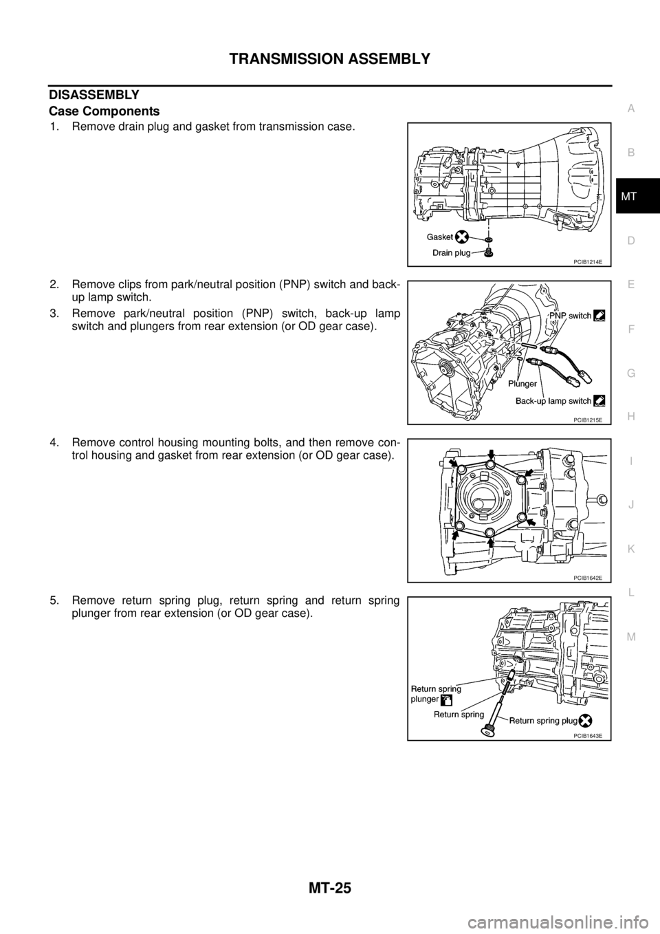
1. Remove drain plug and gasket from transmission case.
2. Remove clips from park/neutral position (PNP) switch and back-
up lamp switch.
3. Remove park/neutral position (PNP) switch, back-up lamp
switch and plungers from rear extension (or OD gear case).
4. Remove control housing mounting bolts, and then remove con-
trol housing and gasket from rear extension (or OD gear case).
5. Remove return spring plug, return spring and return spring
plunger from rear extension (or OD gear case).
PCIB1214E
PCIB1215E
PCIB1642E
PCIB1643E
Page 2381 of 3171
MT-64
TRANSMISSION ASSEMBLY
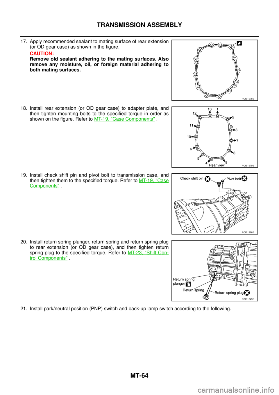
17. Apply recommended sealant to mating surface of rear extension
(or OD gear case) as shown in the figure.
CAUTION:
Remove old sealant adhering to the mating surfaces. Also
remove any moisture, oil, or foreign material adhering to
both mating surfaces.
18. Install rear extension (or OD gear case) to adapter plate, and
then tighten mounting bolts to the specified torque in order as
shown on the figure. Refer toMT-19, "
Case Components".
19. Install check shift pin and pivot bolt to transmission case, and
then tighten them to the specified torque. Refer toMT-19, "
Case
Components".
20. Install return spring plunger, return spring and return spring plug
to rear extension (or OD gear case), and then tighten return
spring plug to the specified torque. Refer toMT-23, "
Shift Con-
trol Components".
21. Install park/neutral position (PNP) switch and back-up lamp switch according to the following.
PCIB1278E
PCIB1279E
PCIB1226E
PCIB1643E
Page 2382 of 3171
TRANSMISSION ASSEMBLY
MT-65
D
E
F
G
H
I
J
K
L
MA
B
MT
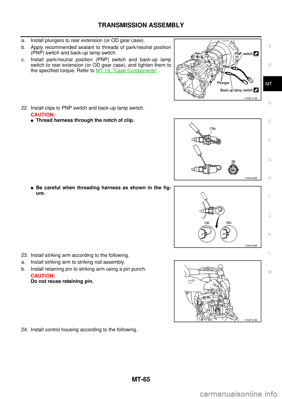
a. Install plungers to rear extension (or OD gear case).
b. Apply recommended sealant to threads of park/neutral position
(PNP) switch and back-up lamp switch.
c. Install park/neutral position (PNP) switch and back-up lamp
switch to rear extension (or OD gear case), and tighten them to
the specified torque. Refer toMT-19, "
Case Components".
22. Install clips to PNP switch and back-up lamp switch.
CAUTION:
lThread harness through the notch of clip.
lBe careful when threading harness as shown in the fig-
ure.
23. Install striking arm according to the following.
a. Install striking arm to striking rod assembly.
b. Install retaining pin to striking arm using a pin punch.
CAUTION:
Do not reuse retaining pin.
24. Install control housing according to the following.
PCIB1215E
PCIB1638E
PCIB1639E
PCIB1219E
Page 2598 of 3171

HARNESS
PG-69
C
D
E
F
G
H
I
J
L
MA
B
PG
FTS EC Fuel Pump Temperature Sensor
GLOW EC Glow Control System
H/AIM LT Headlamp Aiming Control System
H/LAMP LT Headlamp
HEATUP EC Heat Up Switch
HLC WW Headlamp Washer
HORN WW Horn
HSEAT SE Heated Seat
I/KEY BL Intelligent Key System
I/MIRR GW Inside Mirror (Auto Anti-dazzling Mirror)
IATS EC Intake Air Temperature Sensor
ILL LT Illumination
INJ/PW EC Fuel Injector Power Supply
INJECT EC Fuel Injector
INT/L LT Room and Map Lamps
INT/V EC Intake Air Control Valve Control Solenoid Valve
MAFS EC Mass Air Flow Sensor
MAIN AT Main Power Supply and Ground Circuit
MAIN EC Main Power Supply and Ground Circuit
METER DI Speedometer, Tachometer, Temp. and Fuel Gauges
MIL/DL EC Malfunction Indicator Lamp, Data Link Connector
MIRROR GW Door Mirror
MMSW AT Manual Mode Switch
MULTI BL Multi-remote Control System
NATS BL NATS (Nissan Anti-Theft System)
NAVI AV Navigation System
NONDTC AT NON-detective Items
P/SCKT WW Power Socket
PHONE AV Telephone
PNP/SW AT Park/Neutral Position Switch
PNP/SW EC Park/Neutral Position Switch
POWER PG Power Supply Routing
R/FOG LT Rear Fog Lamp
RP/SEN EC Refrigerant Pressure Sensor
S/LOCK BL Power Door Lock — Super Lock
S/SIG EC Start Signal
SEAT SE Power Seat
SHIFT AT A/T Shift Lock System
SROOF RF Sunroof
SRS SRS Supplemental Restraint System
START SC Starting System
STOP/L LT Stop Lamp
STSIG AT Start Signal Circuit
T/F TF TransferCode Section Wiring Diagram Name
Page 2624 of 3171
REAR PROPELLER SHAFT
PR-9
C
E
F
G
H
I
J
K
L
MA
B
PR
REMOVAL
1. Move the A/T select lever to the N position or set M/T shift lever to neutral position.
2. Release the parking brake.
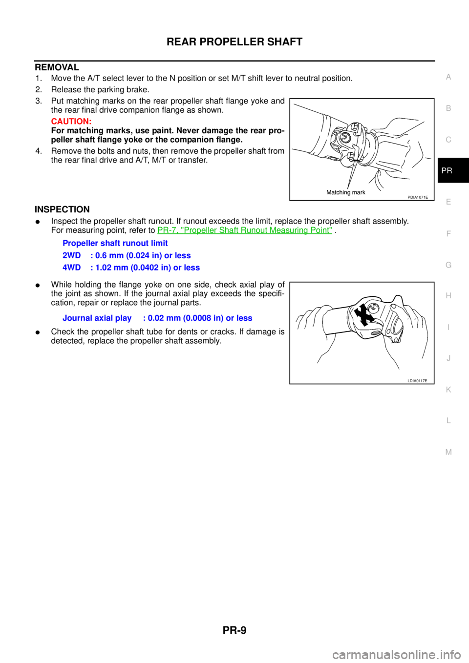
3. Put matching marks on the rear propeller shaft flange yoke and
the rear final drive companion flange as shown.
CAUTION:
For matching marks, use paint. Never damage the rear pro-
peller shaft flange yoke or the companion flange.
4. Remove the bolts and nuts, then remove the propeller shaft from
the rear final drive and A/T, M/T or transfer.
INSPECTION
lInspect the propeller shaft runout. If runout exceeds the limit, replace the propeller shaft assembly.
For measuring point, refer toPR-7, "
Propeller Shaft Runout Measuring Point".
lWhile holding the flange yoke on one side, check axial play of
the joint as shown. If the journal axial play exceeds the specifi-
cation, repair or replace the journal parts.
lCheck the propeller shaft tube for dents or cracks. If damage is
detected, replace the propeller shaft assembly.
PDIA1071E
Propeller shaft runout limit
2WD : 0.6 mm (0.024 in) or less
4WD : 1.02 mm (0.0402 in) or less
Journal axial play : 0.02 mm (0.0008 in) or less
LDIA0117E
Page 2628 of 3171

PS-1
POWER STEERING SYSTEM
G STEERING
CONTENTS
C
D
E
F
H
I
J
K
L
M
SECTIONPS
A
B
PS
POWER STEERING SYSTEM
PRECAUTIONS .......................................................... 2
Precautions for Supplemental Restraint System
(SRS)“AIRBAG”and“SEATBELTPRE-TEN-
SIONER” .................................................................. 2
Precautions for Steering System .............................. 2
PREPARATION ........................................................... 3
Special Service Tools [SST] ..................................... 3
Commercial Service Tools ........................................ 4
NOISE, VIBRATION, AND HARSHNESS (NVH)
TROUBLESHOOTING ................................................ 5
NVH Troubleshooting Chart ..................................... 5
POWER STEERING FLUID ........................................ 6
Checking Fluid Level ................................................ 6
Checking Fluid Leakage ........................................... 6
Air Bleeding Hydraulic System ................................. 6
STEERING WHEEL .................................................... 8
On-Vehicle Inspection and Service .......................... 8
CHECKING CONDITION OF INSTALLATION ...... 8
CHECKING STEERING WHEEL PLAY ................ 8
CHECKING NEUTRAL POSITION STEERING
WHEEL ................................................................. 8
CHECKING STEERING WHEEL TURNING
FORCE .................................................................. 8
CHECKING FRONT WHEEL TURNING ANGLE..... 9
Removal and Installation ........................................ 10
REMOVAL ........................................................... 10
INSTALLATION ................................................... 10
STEERING COLUMN ................................................11
Removal and Installation ......................................... 11
COMPONENT ...................................................... 11
REMOVAL ............................................................ 11
INSPECTION AFTER REMOVAL ....................... 12
INSTALLATION ................................................... 12
INSPECTION AFTER INSTALLATION ............... 13
POWER STEERING GEAR AND LINKAGE ............ 14Removal and Installation ........................................ 14
COMPONENT ..................................................... 14
REMOVAL ........................................................... 14
INSTALLATION ................................................... 15
INSPECTION AFTER INSTALLATION ................ 15
Disassembly and Assembly .................................... 16
COMPONENT ..................................................... 16
DISASSEMBLY ................................................... 17
INSPECTION AFTER DISASSEMBLY ................ 18
ASSEMBLY ......................................................... 20
POWER STEERING OIL PUMP ............................... 25
On-Vehicle Inspection and Service ......................... 25
CHECKING RELIEF OIL PRESSURE ................ 25
Removal and Installation ........................................ 25
REMOVAL ........................................................... 25
INSTALLATION ................................................... 26
Disassembly and Assembly .................................... 26
COMPONENT ..................................................... 26
INSPECTION BEFORE DISASSEMBLY ............. 26
DISASSEMBLY ................................................... 27
INSPECTION AFTER DISASSEMBLY ................ 27
ASSEMBLY ......................................................... 28
HYDRAULIC LINE .................................................... 30
Component (RHD Models) ..................................... 30
Component (LHD Models) ...................................... 32
Removal and Installation ........................................ 33
SERVICE DATA AND SPECIFICATIONS (SDS) ...... 34
Steering Wheel ....................................................... 34
Steering Angle ........................................................ 34
Steering Column ..................................................... 34
Steering Outer Socket and Inner Socket ................ 34
Steering Gear ......................................................... 35
Oil Pump ................................................................. 35
Steering Fluid .......................................................... 35
Page 2635 of 3171
PS-8
STEERING WHEEL
STEERING WHEEL
PFP:48430
On-Vehicle Inspection and ServiceEGS001LG
CHECKING CONDITION OF INSTALLATION
lCheck installation conditions of steering gear assembly, front suspension assembly, axle and steering col-
umn assembly.
lCheck if movement exists when steering wheel is moved up and down, to the left and right and to the axial
direction.
lCheck steering gear assembly mounting bolts and nuts for looseness. Refer toPS-14, "COMPONENT".
CHECKING STEERING WHEEL PLAY
lTurn steering wheel so that front wheels come to the straight-ahead position. Start engine and lightly turn
steering wheel to the left and right until front wheels start to move. Measure steering wheel movement on
the outer circumference.
lWhen the measurement value is outside the standard value, check backlash for each joint of steering col-
umn assembly and installation condition of steering gear assembly.
CHECKING NEUTRAL POSITION STEERING WHEEL
lMake sure that steering gear assembly, steering column assembly and steering wheel are installed in the
correct position.
lPerform neutral position inspection after wheel alignment. Refer toFSU-7, "Front Wheel Alignment".
lSet vehicle to the straight-ahead position and confirm steering wheel is in the neutral position.
lLoosen outer socket lock nut and turn inner socket to left and right equally to make fine adjustment if
steering wheel is not in the neutral position.
CHECKING STEERING WHEEL TURNING FORCE
1. Park vehicle on a level and dry surface, set parking brake.
2. Start engine.
3. Bring power steering fluid up to adequate operating temperature. [Make sure temperature of fluid is
approximately 50 to 80°C(122to176°F).]
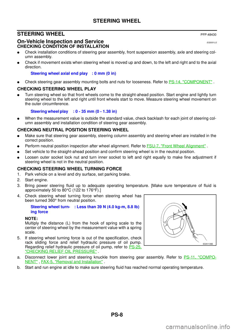
4. Check steering wheel turning force when steering wheel has
been turned 360°from neutral position.
NOTE:
Multiply the distance (L) from the hook of spring scale to the
center of steering wheel by the measurement value with a spring
scale.
5. If steering wheel turning force is out of the specification, check
rack sliding force and relief hydraulic pressure of oil pump.
Regarding relief hydraulic pressure of oil pump, refer toPS-25,
"CHECKING RELIEF OIL PRESSURE".
a. Disconnect lower joint and steering knuckle from steering gear assembly. Refer toPS-11, "
COMPO-
NENT",FAX-5, "Removal and Installation".
b. Start and run engine at idle to make sure steering fluid has reached normal operating temperature.Steering wheel axial end play : 0 mm (0 in)
Steering wheel play : 0 - 35 mm (0 - 1.38 in)
Steering wheel turn-
ing force: Less than 39 N (4.0 kg-m, 8.8 lb)
SGIA1136E