Neutral position NISSAN NAVARA 2005 Repair Owner's Manual
[x] Cancel search | Manufacturer: NISSAN, Model Year: 2005, Model line: NAVARA, Model: NISSAN NAVARA 2005Pages: 3171, PDF Size: 49.59 MB
Page 1019 of 3171
TROUBLE DIAGNOSIS
EC-39
C
D
E
F
G
H
I
J
K
L
MA
EC
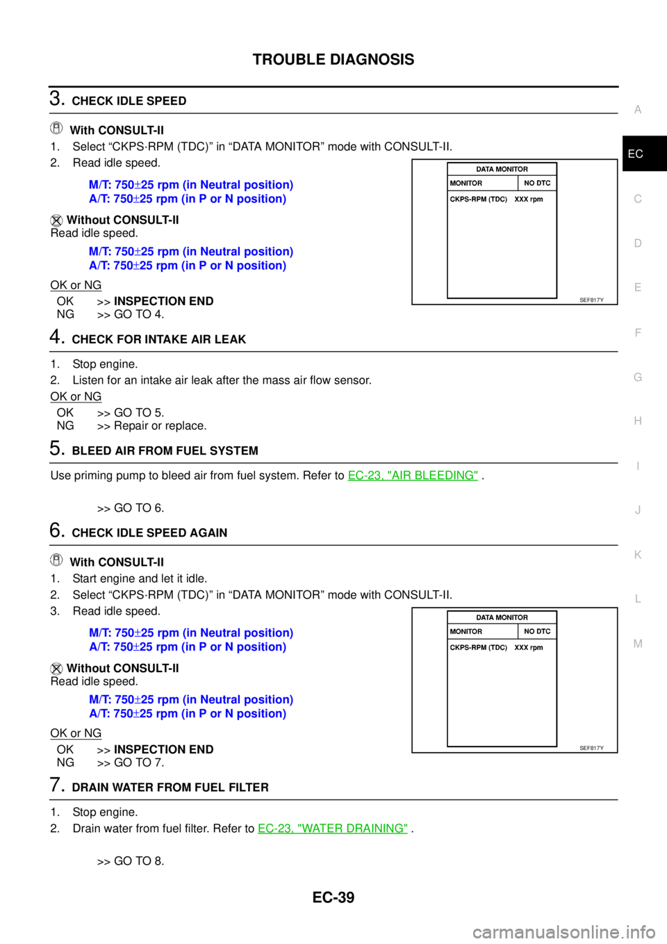
3.CHECK IDLE SPEED
With CONSULT-II
1. Select “CKPS·RPM (TDC)” in “DATA MONITOR” mode with CONSULT-II.
2. Read idle speed.
Without CONSULT-II
Read idle speed.
OK or NG
OK >>INSPECTION END
NG >> GO TO 4.
4.CHECK FOR INTAKE AIR LEAK
1. Stop engine.
2. Listen for an intake air leak after the mass air flow sensor.
OK or NG
OK >> GO TO 5.
NG >> Repair or replace.
5.BLEED AIR FROM FUEL SYSTEM
Use priming pump to bleed air from fuel system. Refer toEC-23, "
AIR BLEEDING".
>> GO TO 6.
6.CHECK IDLE SPEED AGAIN
With CONSULT-II
1. Start engine and let it idle.
2. Select “CKPS·RPM (TDC)” in “DATA MONITOR” mode with CONSULT-II.
3. Read idle speed.
Without CONSULT-II
Read idle speed.
OK or NG
OK >>INSPECTION END
NG >> GO TO 7.
7.DRAIN WATER FROM FUEL FILTER
1. Stop engine.
2. Drain water from fuel filter. Refer toEC-23, "
WATER DRAINING".
>> GO TO 8. M/T: 750±25 rpm (in Neutral position)
A/T: 750±25 rpm (in P or N position)
M/T: 750±25 rpm (in Neutral position)
A/T: 750±25 rpm (in P or N position)
SEF817Y
M/T: 750±25 rpm (in Neutral position)
A/T: 750±25 rpm (in P or N position)
M/T: 750±25 rpm (in Neutral position)
A/T: 750±25 rpm (in P or N position)
SEF817Y
Page 1020 of 3171
EC-40
TROUBLE DIAGNOSIS
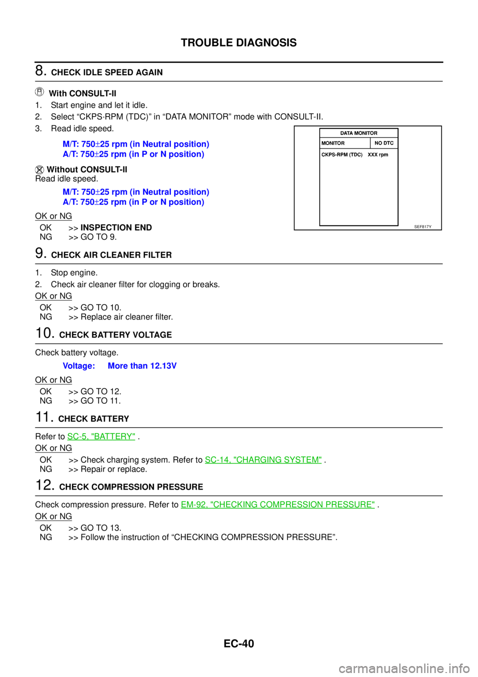
8.CHECK IDLE SPEED AGAIN
With CONSULT-II
1. Start engine and let it idle.
2. Select “CKPS·RPM (TDC)” in “DATA MONITOR” mode with CONSULT-II.
3. Read idle speed.
Without CONSULT-II
Read idle speed.
OK or NG
OK >>INSPECTION END
NG >> GO TO 9.
9.CHECK AIR CLEANER FILTER
1. Stop engine.
2. Check air cleaner filter for clogging or breaks.
OK or NG
OK >> GO TO 10.
NG >> Replace air cleaner filter.
10.CHECK BATTERY VOLTAGE
Check battery voltage.
OK or NG
OK >> GO TO 12.
NG >> GO TO 11.
11 .CHECK BATTERY
Refer toSC-5, "
BATTERY".
OK or NG
OK >> Check charging system. Refer toSC-14, "CHARGING SYSTEM".
NG >> Repair or replace.
12.CHECK COMPRESSION PRESSURE
Check compression pressure. Refer toEM-92, "
CHECKING COMPRESSION PRESSURE".
OK or NG
OK >> GO TO 13.
NG >> Follow the instruction of “CHECKING COMPRESSION PRESSURE”.M/T: 750±25 rpm (in Neutral position)
A/T: 750±25 rpm (in P or N position)
M/T: 750±25 rpm (in Neutral position)
A/T: 750±25 rpm (in P or N position)
SEF817Y
Voltage: More than 12.13V
Page 1021 of 3171
TROUBLE DIAGNOSIS
EC-41
C
D
E
F
G
H
I
J
K
L
MA
EC
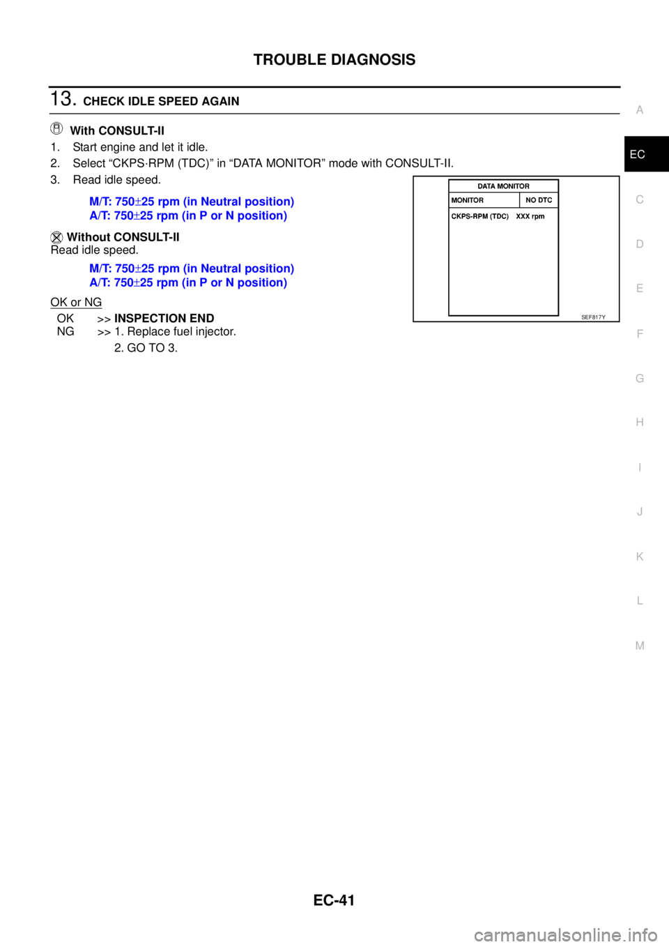
13.CHECK IDLE SPEED AGAIN
With CONSULT-II
1. Start engine and let it idle.
2. Select “CKPS·RPM (TDC)” in “DATA MONITOR” mode with CONSULT-II.
3. Read idle speed.
Without CONSULT-II
Read idle speed.
OK or NG
OK >>INSPECTION END
NG >> 1. Replace fuel injector.
2. GO TO 3. M/T: 750±25 rpm (in Neutral position)
A/T: 750±25 rpm (in P or N position)
M/T: 750±25 rpm (in Neutral position)
A/T: 750±25 rpm (in P or N position)SEF817Y
Page 1038 of 3171
![NISSAN NAVARA 2005 Repair Owners Manual EC-58
TROUBLE DIAGNOSIS
: Average voltage for pulse signal (Actual pulse signal can be confirmed by oscilloscope.)101 W ASCD brake switch[Ignition switch ON]
lBrake pedal: Fully released (A/T)
lClutch](/img/5/57362/w960_57362-1037.png "NISSAN NAVARA 2005 Repair Owners Manual EC-58
TROUBLE DIAGNOSIS
: Average voltage for pulse signal (Actual pulse signal can be confirmed by oscilloscope.)101 W ASCD brake switch[Ignition switch ON]
lBrake pedal: Fully released (A/T)
lClutch")
EC-58
TROUBLE DIAGNOSIS
: Average voltage for pulse signal (Actual pulse signal can be confirmed by oscilloscope.)101 W ASCD brake switch[Ignition switch ON]
lBrake pedal: Fully released (A/T)
lClutch pedal and brake pedal:
Fully released (M/T)BATTERY VOLTAGE
(11 - 14V)
[Ignition switch ON]
lBrake pedal: Slightly depressed (A/T)
lClutch pedal and/or brake pedal:
Slightly depressed (M/T)Approximately 0V
102 SB ASCD steering switch[Ignition switch ON]
lASCD steering switch: OFFApproximately 4.3V
[Ignition switch ON]
lON/OFF switch: PressedApproximately 0.3V
[Ignition switch ON]
lCANCEL switch: PressedApproximately 1.3V
[Ignition switch ON]
lRESUME/ACCELERATE switch: PressedApproximately 3.3V
[Ignition switch ON]
lSET/COAST switch: PressedApproximately 2.3V
103 BASCD steering switch
ground[Ignition switch ON]Approximately 0.3V
105 BR ECM relay (self shut-off)[Ignition switch ON]
[Ignition switch OFF]
lFor a few seconds after turning ignition
switch OFFApproximately 1.0V
[Ignition switch OFF]
lMore than a few seconds after turning igni-
tion switch OFFBATTERY VOLTAGE
(11 - 14V)
107
108R
RIgnition switch[Ignition switch ON]BATTERY VOLTAGE
(11 - 14V)
11 0G(A/T)
O (M/T)Park/Neutral position switch[Ignition switch ON]
lShift lever: P or N (A/T), Neutral (M/T)Approximately 0V
[Ignition switch ON]
lExcept the above positionBATTERY VOLTAGE
(11 - 14V)
113 BR ECM relay (self shut-off)[Ignition switch ON]
[Ignition switch OFF]
lFor a few seconds after turning ignition
switch OFFApproximately 1.0V
[Ignition switch OFF]
lMore than a few seconds after turning igni-
tion switch OFFBATTERY VOLTAGE
(11 - 14V)
114 B ECM ground[Engine is running]
lIdle speedApproximately 0V
11 9
120R
GPower supply for ECM[Ignition switch ON]BATTERY VOLTAGE
(11 - 14V)
121 VPower supply for ECM
(Back-up)[Ignition switch OFF]BATTERY VOLTAGE
(11 - 14V) TERMI-
NAL
NO.WIRE
COLORITEM CONDITIONDATA
(DC Voltage and Pulse Signal)
Page 1040 of 3171

EC-60
TROUBLE DIAGNOSIS
ENGINE CONTROL COMPONENT PARTS/CONTROL SYSTEMS APPLICATION
X: ApplicableItemDIAGNOSTIC TEST MODE
SELF-DIAG RESULTS
DATA MON-
ITORACTIVE
TEST
DTCFREEZE
FRAME
DATA
ENGINE CONTROL COMPONENT PARTS
INPUTCrankshaft position sensor´´´
Camshaft position sensor´
Engine coolant temperature sensor´´´´
Vehicle speed signal´´´
Fuel pump temperature sensor´´
Accelerator pedal position sensor 1´´
Accelerator pedal position sensor 2´´
Fuel rail pressure sensor´´
Mass air flow sensor´´
Intake air temperature sensor´
Turbocharger boost sensor´´´
Refrigerant pressure sensor´
Battery voltage´´
Park/neutral position (PNP) switch´
Heat up switch´
Stop lamp switch´´
Barometric pressure sensor (built-into ECM)´´
ASCD steering switch´´
ASCD brake switch´´
ASCD clutch switch´´
OUTPUTFuel pump´´´
Fuel injector´´´
Glow relay´´
Cooling fan relay´´´
Turbocharger boost control solenoid valve´
Intake air control valve control solenoid valve
EGR volume control valve´´
Page 1043 of 3171
![NISSAN NAVARA 2005 Repair Owners Manual TROUBLE DIAGNOSIS
EC-63
C
D
E
F
G
H
I
J
K
L
MA
ECACT CR PRESS [MPa]´´
lThe Fuel rail pressure (determined by
the signal voltage of the fuel rail pres-
sure sensor) is displayed.
BATTERY VOLT [V]´´](/img/5/57362/w960_57362-1042.png "NISSAN NAVARA 2005 Repair Owners Manual TROUBLE DIAGNOSIS
EC-63
C
D
E
F
G
H
I
J
K
L
MA
ECACT CR PRESS [MPa]´´
lThe Fuel rail pressure (determined by
the signal voltage of the fuel rail pres-
sure sensor) is displayed.
BATTERY VOLT [V]´´")
TROUBLE DIAGNOSIS
EC-63
C
D
E
F
G
H
I
J
K
L
MA
ECACT CR PRESS [MPa]´´
lThe Fuel rail pressure (determined by
the signal voltage of the fuel rail pres-
sure sensor) is displayed.
BATTERY VOLT [V]´´
lThe power supply voltage of ECM is
displayed.
P/N POSI SW [ON/OFF]´´
lIndicates [ON/OFF] condition from the
park/neutral position switch signal.
START SIGNAL [ON/OFF]´´
lIndicates [ON/OFF] condition from the
starter signal.
AIR COND SIG [ON/OFF]´´
lIndicates [ON/OFF] condition of the air
conditioner switch as determined by
the air conditioner signal.
BRAKE SW [ON/OFF]´´
lIndicates [ON/OFF] condition from the
stop lamp switch signal.
BRAKE SW2 [ON/OFF]´´
lIndicates [ON/OFF] condition from the
ASCD brake switch and ASCD clutch
switch signal.
IGN SW [ON/OFF]´´
lIndicates [ON/OFF] condition from
ignition switch signal.
WARM UP SW [ON/OFF]´
lIndicates [ON/OFF] condition from
heat up switch signal.
MAS AIR/FL SE [V]´´
lThe signal voltage of the mass air flow
sensor is displayed.This signal is converted by ECM inter-
nally. Thus, these differ from ECM termi-
nals voltage.
MAIN INJ WID [msec]´
lIndicates the actual fuel injection pulse
width compensated by ECM according
to the input signals.
PUMP CURRENT [mA]´
lIndicates the fuel pump power supply
current from the ECM.
GLOW RLY [ON/OFF]´
lThe glow relay control condition
(determined by ECM according to the
input signal) is displayed.
COOLING FAN
[LOW/HI/OFF]´
lIndicates the control condition of the
cooling fans (determined by ECM
according to the input signal).
LOW ... Operates at low speed
HI ... Operates at high speed
OFF ... Stopped
EGR VOL CON/V [step]´
lIndicates the EGR volume control
value computed by the ECM accord-
ing to the input signals.
lThe opening becomes larger as the
value increases.
INT/A VOLUME [mg/]
lThe intake air volume computed from
the mass air flow sensor signal is dis-
played.
BARO SEN [kPa]´´
lThe barometric pressure (determined
by the signal voltage from the absolute
pressure sensor built into the ECM) is
displayed. MONITOR ITEMECM
INPUT
SIG-
NALMAIN
SIG-
NALSCONDITION SPECIFICATION
Page 1283 of 3171

EGR VOLUME CONTROL SYSTEM
EC-303
C
D
E
F
G
H
I
J
K
L
MA
EC
CONSULT-II Reference Value in Data Monitor ModeEBS01KLS
Specification data are reference values.
ECM Terminals and Reference ValueEBS01KLT
Specification data are reference values and are measured between each terminal and ground.
CAUTION:
Do not use ECM ground terminals when measuring input/output voltage. Doing so may result in dam-
age to the ECM's transistor. Use a ground other than ECM terminals, such as the ground.
MONITOR ITEM CONDITION SPECIFICATION
EGR VOL CON/V
lEngine: After warming up
lAir conditioner switch: OFF
lShift lever: P or N (A/T), Neutral (M/T)
lNo loadAfter 1 minute at idle More than 10 steps
Revving engine from idle to 3,200
rpm0step
TERMI-
NAL
NO.WIRE
COLORITEM CONDITIONDATA
(DC Voltage)
25
26
27
28Y
O
GR
VEGR volume control valve[Engine is running]
lWarm-up condition
lIdle speed0.1 - 14V
(Voltage signals of each ECM ter-
minals differ according to the con-
trol position of EGR volume
control valve.)
105
11 3BR
BRECM relay (self shut-off)[Ignition switch ON]
[Ignition switch OFF]
lFor a few seconds after turning ignition switch
OFFApproximately 1.0V
[Ignition switch OFF]
lMore than a few seconds passed after turning
ignition switch OFFBATTERY VOLTAGE
(11 - 14V)
11 9
120R
GPower supply for ECM[Ignition switch ON]BATTERY VOLTAGE
(11 - 14V)
Page 1322 of 3171

EC-342
PNP SWITCH
PNP SWITCH
PFP:32006
DescriptionEBS01KMR
When the gear position is in P or N (A/T), Neutral (M/T), park/neutral position is ON. ECM detects the position
because the continuity of the line (the ON signal) exists.
CONSULT-II Reference Value in Data Monitor ModeEBS01KMS
Specification data are reference values.
ECM Terminals and Reference ValueEBS01KMT
Specification data are reference values and are measured between each terminal and ground.
CAUTION:
Do not use ECM ground terminals when measuring input/output voltage. Doing so may result in dam-
age to the ECM's transistor. Use a ground other than ECM terminals, such as the ground.
MONITOR ITEM CONDITION SPECIFICATION
P/N POSI SW
lIgnition switch: ONShift lever: P or N (A/T), Neutral (M/T) ON
Shift lever: Except above OFF
TERMI-
NAL
NO.WIRE
COLORITEM CONDITIONDATA
(DC Voltage)
11 0G(A/T)
O(M/T)Park/Neutral position switch[Ignition switch ON]
lShift lever: P or N (A/T), Neutral (M/T)Approximately 0V
[Ignition switch ON]
lShift lever: Except aboveBATTERY VOLTAGE
(11 - 14V)
Page 1326 of 3171
EC-346
PNP SWITCH
M/T MODELS
1.CHECK OVERALL FUNCTION
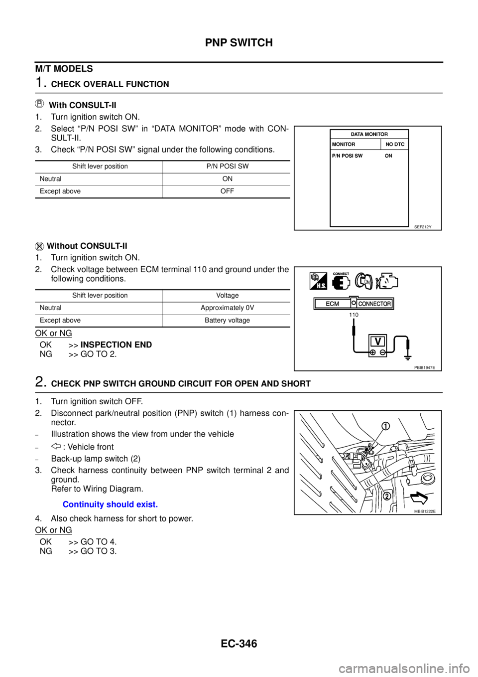
With CONSULT-II
1. Turn ignition switch ON.
2. Select “P/N POSI SW” in “DATA MONITOR” mode with CON-
SULT-II.
3. Check “P/N POSI SW” signal under the following conditions.
Without CONSULT-II
1. Turn ignition switch ON.
2. Check voltage between ECM terminal 110 and ground under the
following conditions.
OK or NG
OK >>INSPECTION END
NG >> GO TO 2.
2.CHECK PNP SWITCH GROUND CIRCUIT FOR OPEN AND SHORT
1. Turn ignition switch OFF.
2. Disconnect park/neutral position (PNP) switch (1) harness con-
nector.
–Illustration shows the view from under the vehicle
–: Vehicle front
–Back-up lamp switch (2)
3. Check harness continuity between PNP switch terminal 2 and
ground.
Refer to Wiring Diagram.
4. Also check harness for short to power.
OK or NG
OK >> GO TO 4.
NG >> GO TO 3.
Shift lever position P/N POSI SW
Neutral ON
Except above OFF
SEF212Y
Shift lever position Voltage
Neutral Approximately 0V
Except above Battery voltage
PBIB1947E
Continuity should exist.MBIB1222E
Page 1327 of 3171
PNP SWITCH
EC-347
C
D
E
F
G
H
I
J
K
L
MA
EC
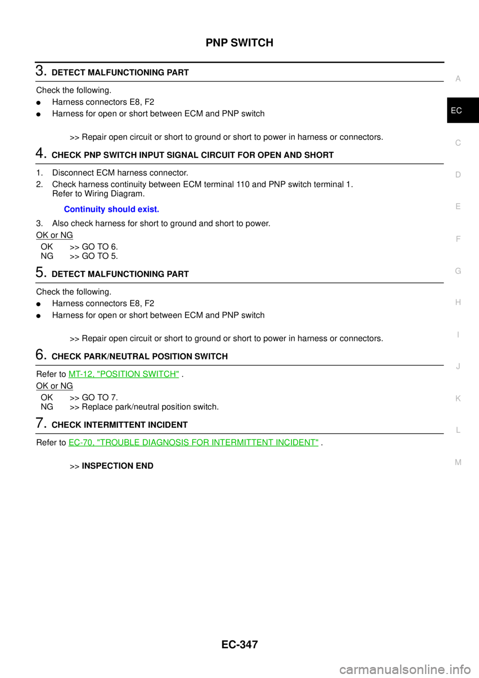
3.DETECT MALFUNCTIONING PART
Check the following.
lHarness connectors E8, F2
lHarness for open or short between ECM and PNP switch
>> Repair open circuit or short to ground or short to power in harness or connectors.
4.CHECK PNP SWITCH INPUT SIGNAL CIRCUIT FOR OPEN AND SHORT
1. Disconnect ECM harness connector.
2. Check harness continuity between ECM terminal 110 and PNP switch terminal 1.
Refer to Wiring Diagram.
3. Also check harness for short to ground and short to power.
OK or NG
OK >> GO TO 6.
NG >> GO TO 5.
5.DETECT MALFUNCTIONING PART
Check the following.
lHarness connectors E8, F2
lHarness for open or short between ECM and PNP switch
>> Repair open circuit or short to ground or short to power in harness or connectors.
6.CHECK PARK/NEUTRAL POSITION SWITCH
Refer toMT-12, "
POSITION SWITCH".
OK or NG
OK >> GO TO 7.
NG >> Replace park/neutral position switch.
7.CHECK INTERMITTENT INCIDENT
Refer toEC-70, "
TROUBLE DIAGNOSIS FOR INTERMITTENT INCIDENT".
>>INSPECTION END Continuity should exist.