NISSAN NAVARA 2005 Repair Repair Manual
NAVARA 2005
NISSAN
NISSAN
https://www.carmanualsonline.info/img/5/57362/w960_57362-0.png
NISSAN NAVARA 2005 Repair Repair Manual
Page 287 of 3171
DISASSEMBLY
AT-279
D
E
F
G
H
I
J
K
L
MA
B
AT
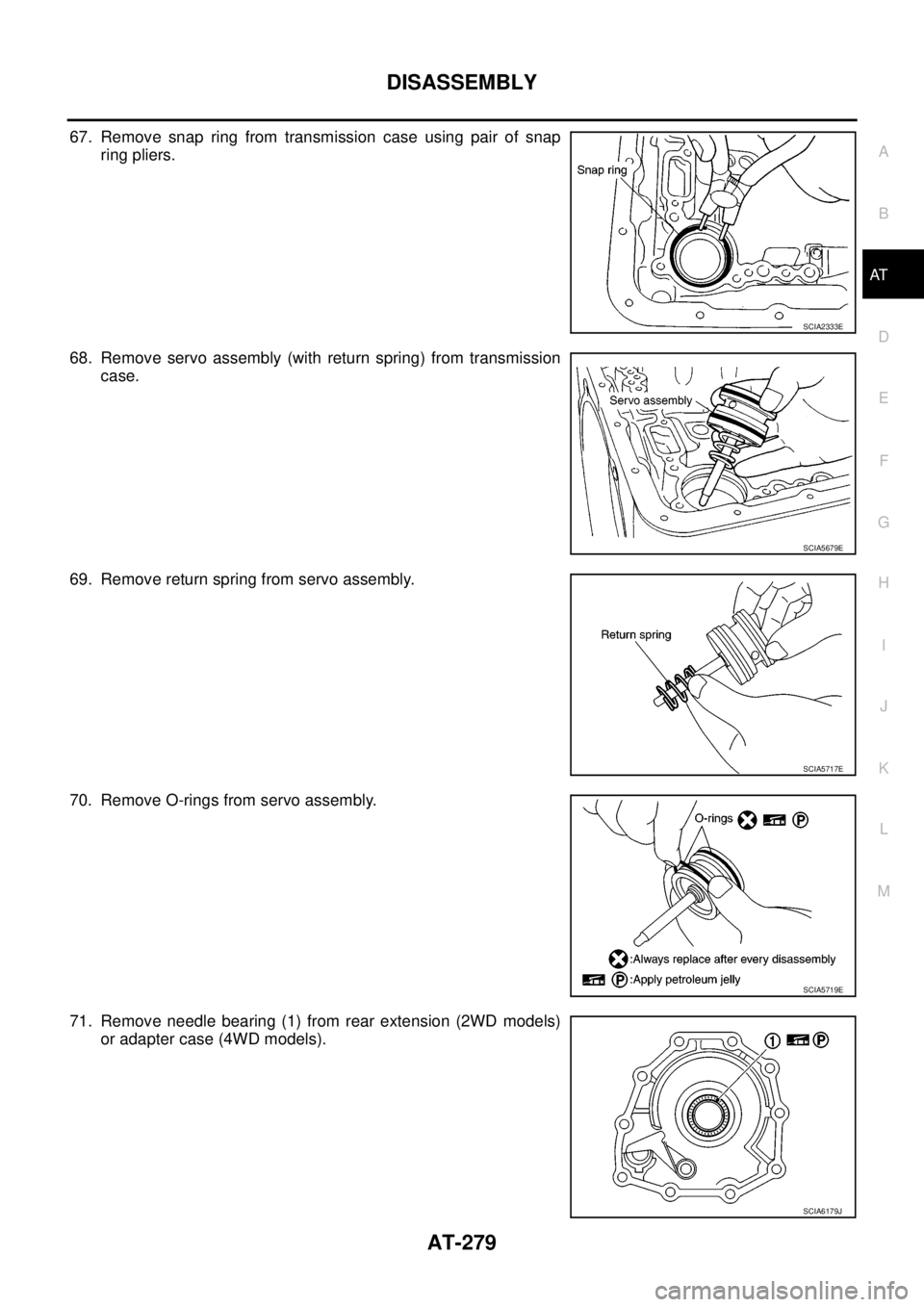
67. Remove snap ring from transmission case using pair of snap
ring pliers.
68. Remove servo assembly (with return spring) from transmission
case.
69. Remove return spring from servo assembly.
70. Remove O-rings from servo assembly.
71. Remove needle bearing (1) from rear extension (2WD models)
or adapter case (4WD models).
SCIA2333E
SCIA5679E
SCIA5717E
SCIA5719E
SCIA6179J
Page 308 of 3171
AT-300
ASSEMBLY
ASSEMBLY
PFP:00000
Assembly (1)ECS00G3L
1. As shown in the figure, use a drift [commercial service tool: 22
mm (0.87 in) dia.] to drive manual shaft oil seals into transmis-
sion case until it is flush.
CAUTION:
lApply ATF to manual shaft oil seals.
lDo not reuse manual shaft oil seals.
2. Install detent spring and spacer to transmission case and then
tighten mounting dolts to the specified torque. Refer toAT-251,
"Components".
3. Install manual shaft to transmission case.
4. Install parking rod to manual plate.
SCIA5259E
SCIA5248E
SCIA5716E
SCIA5220E
Page 309 of 3171
ASSEMBLY
AT-301
D
E
F
G
H
I
J
K
L
MA
B
AT
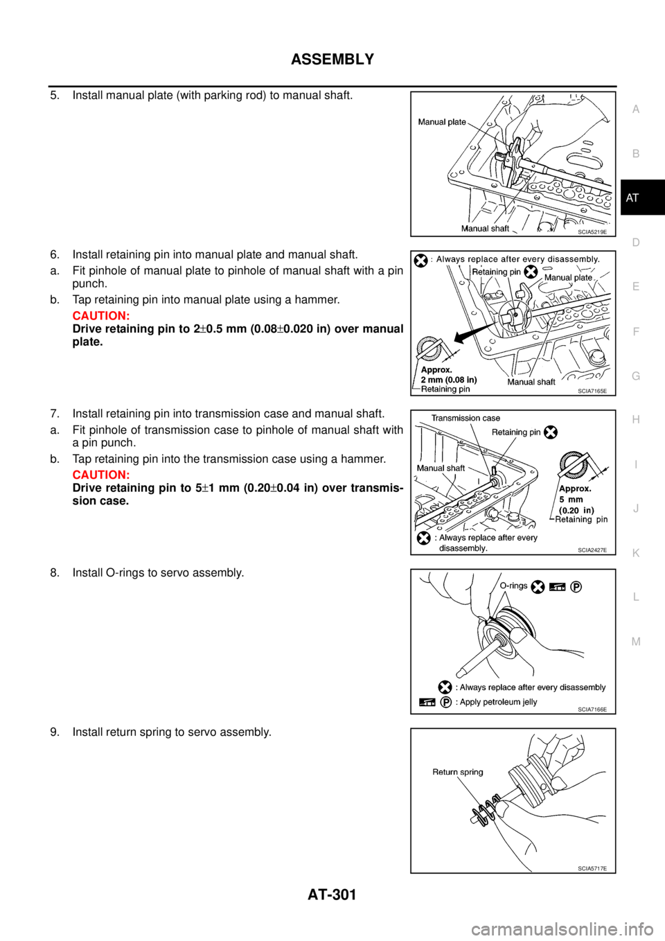
5. Install manual plate (with parking rod) to manual shaft.
6. Install retaining pin into manual plate and manual shaft.
a. Fit pinhole of manual plate to pinhole of manual shaft with a pin
punch.
b. Tap retaining pin into manual plate using a hammer.
CAUTION:
Drive retaining pin to 2±0.5 mm (0.08±0.020 in) over manual
plate.
7. Install retaining pin into transmission case and manual shaft.
a. Fit pinhole of transmission case to pinhole of manual shaft with
a pin punch.
b. Tap retaining pin into the transmission case using a hammer.
CAUTION:
Drive retaining pin to 5±1mm(0.20±0.04 in) over transmis-
sion case.
8. Install O-rings to servo assembly.
9. Install return spring to servo assembly.
SCIA5219E
SCIA7165E
SCIA2427E
SCIA7166E
SCIA5717E
Page 310 of 3171
AT-302
ASSEMBLY
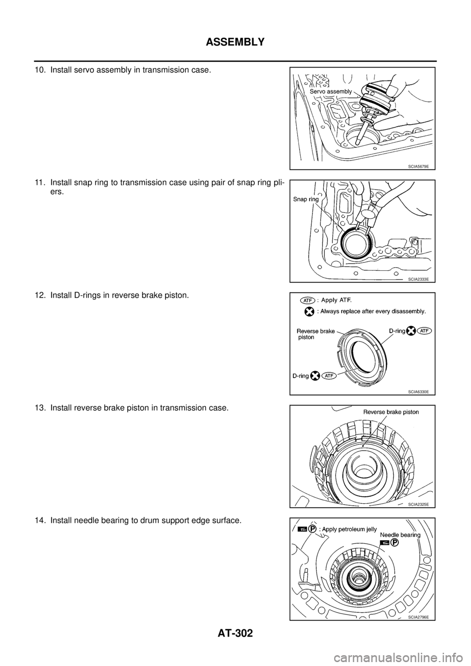
10. Install servo assembly in transmission case.
11. Install snap ring to transmission case using pair of snap ring pli-
ers.
12. Install D-rings in reverse brake piston.
13. Install reverse brake piston in transmission case.
14. Install needle bearing to drum support edge surface.
SCIA5679E
SCIA2333E
SCIA6330E
SCIA2325E
SCIA2796E
Page 311 of 3171
ASSEMBLY
AT-303
D
E
F
G
H
I
J
K
L
MA
B
AT
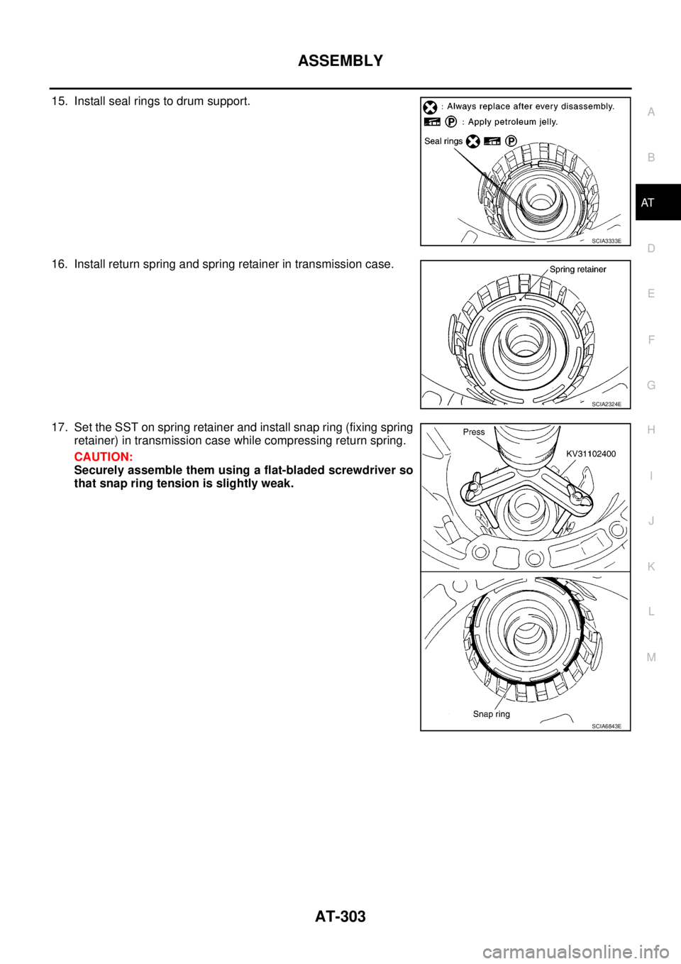
15. Install seal rings to drum support.
16. Install return spring and spring retainer in transmission case.
17. Set the SST on spring retainer and install snap ring (fixing spring
retainer) in transmission case while compressing return spring.
CAUTION:
Securely assemble them using a flat-bladed screwdriver so
that snap ring tension is slightly weak.
SCIA3333E
SCIA2324E
SCIA6843E
Page 312 of 3171
AT-304
ASSEMBLY
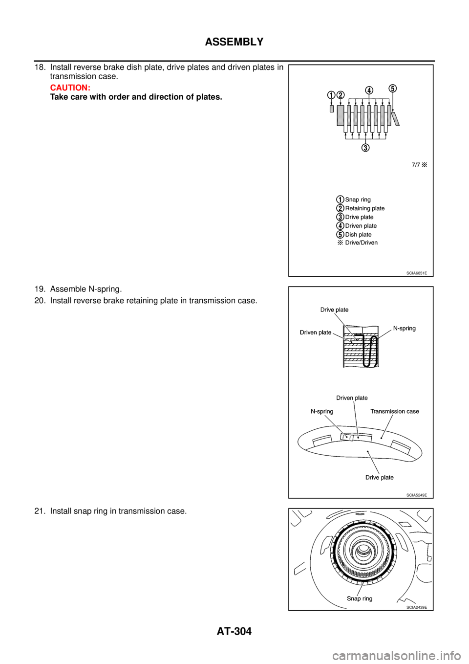
18. Install reverse brake dish plate, drive plates and driven plates in
transmission case.
CAUTION:
Take care with order and direction of plates.
19. Assemble N-spring.
20. Install reverse brake retaining plate in transmission case.
21. Install snap ring in transmission case.
SCIA6851E
SCIA5249E
SCIA2439E
Page 313 of 3171
ASSEMBLY
AT-305
D
E
F
G
H
I
J
K
L
MA
B
AT
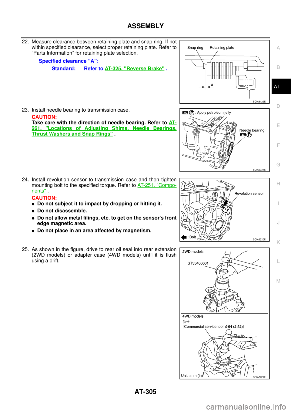
22. Measure clearance between retaining plate and snap ring. If not
within specified clearance, select proper retaining plate. Refer to
“Parts Information” for retaining plate selection.
23. Install needle bearing to transmission case.
CAUTION:
Take care with the direction of needle bearing. Refer toAT-
261, "Locations of Adjusting Shims, Needle Bearings,
Thrust Washers and Snap Rings".
24. Install revolution sensor to transmission case and then tighten
mounting bolt to the specified torque. Refer toAT- 2 5 1 , "
Compo-
nents".
CAUTION:
lDo not subject it to impact by dropping or hitting it.
lDo not disassemble.
lDo not allow metal filings, etc. to get on the sensor's front
edge magnetic area.
lDo not place in an area affected by magnetism.
25. As shown in the figure, drive to rear oil seal into rear extension
(2WD models) or adapter case (4WD models) until it is flush
usingadrift.Specified clearance “A”:
Standard: Refer toAT- 3 2 5 , "
Reverse Brake".
SCIA3129E
SCIA5031E
SCIA2320E
SCIA7221E
Page 315 of 3171
ASSEMBLY
AT-307
D
E
F
G
H
I
J
K
L
MA
B
AT
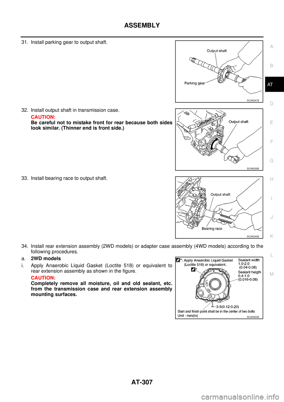
31. Install parking gear to output shaft.
32. Install output shaft in transmission case.
CAUTION:
Be careful not to mistake front for rear because both sides
look similar. (Thinner end is front side.)
33. Install bearing race to output shaft.
34. Install rear extension assembly (2WD models) or adapter case assembly (4WD models) according to the
following procedures.
a.2WD models
i. Apply Anaerobic Liquid Gasket (Loctite 518) or equivalent to
rear extension assembly as shown in the figure.
CAUTION:
Completely remove all moisture, oil and old sealant, etc.
from the transmission case and rear extension assembly
mounting surfaces.
SCIA5247E
SCIA5030E
SCIA5245E
SCIA4934E
Page 316 of 3171
AT-308
ASSEMBLY
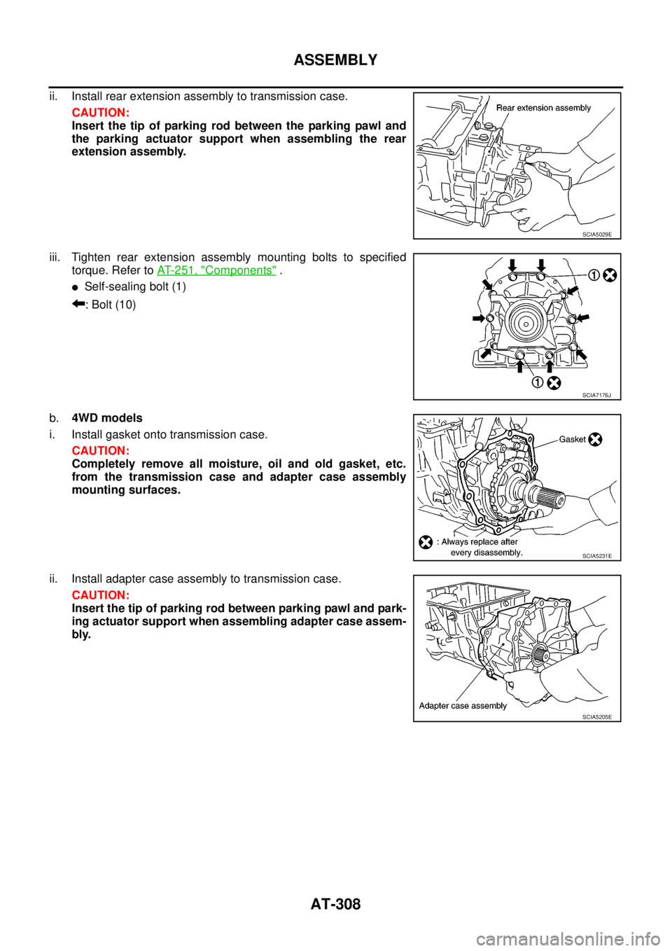
ii. Install rear extension assembly to transmission case.
CAUTION:
Insert the tip of parking rod between the parking pawl and
the parking actuator support when assembling the rear
extension assembly.
iii. Tighten rear extension assembly mounting bolts to specified
torque. Refer toAT- 2 5 1 , "
Components".
lSelf-sealing bolt (1)
:Bolt(10)
b.4WD models
i. Install gasket onto transmission case.
CAUTION:
Completely remove all moisture, oil and old gasket, etc.
from the transmission case and adapter case assembly
mounting surfaces.
ii. Install adapter case assembly to transmission case.
CAUTION:
Insert the tip of parking rod between parking pawl and park-
ing actuator support when assembling adapter case assem-
bly.
SCIA5029E
SCIA7176J
SCIA5231E
SCIA5205E
Page 320 of 3171
AT-312
ASSEMBLY
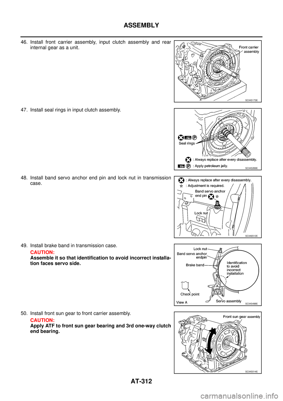
46. Install front carrier assembly, input clutch assembly and rear
internal gear as a unit.
47. Install seal rings in input clutch assembly.
48. Install band servo anchor end pin and lock nut in transmission
case.
49. Install brake band in transmission case.
CAUTION:
Assemble it so that identification to avoid incorrect installa-
tion faces servo side.
50. Install front sun gear to front carrier assembly.
CAUTION:
Apply ATF to front sun gear bearing and 3rd one-way clutch
end bearing.
SCIA5173E
SCIA5269E
SCIA6512E
SCIA5498E
SCIA5014E
![NISSAN NAVARA 2005 Repair Repair Manual AT-300
ASSEMBLY
ASSEMBLY
PFP:00000
Assembly (1)ECS00G3L
1. As shown in the figure, use a drift [commercial service tool: 22
mm (0.87 in) dia.] to drive manual shaft oil seals into transmis-
sion case](/img/5/57362/w960_57362-307.png "NISSAN NAVARA 2005 Repair Repair Manual AT-300
ASSEMBLY
ASSEMBLY
PFP:00000
Assembly (1)ECS00G3L
1. As shown in the figure, use a drift [commercial service tool: 22
mm (0.87 in) dia.] to drive manual shaft oil seals into transmis-
sion case")