oil temperature NISSAN NAVARA 2005 Repair Manual PDF
[x] Cancel search | Manufacturer: NISSAN, Model Year: 2005, Model line: NAVARA, Model: NISSAN NAVARA 2005Pages: 3171, PDF Size: 49.59 MB
Page 2652 of 3171

POWER STEERING OIL PUMP
PS-25
C
D
E
F
H
I
J
K
L
MA
B
PS
POWER STEERING OIL PUMPPFP:49110
On-Vehicle Inspection and ServiceEGS001LL
CHECKING RELIEF OIL PRESSURE
CAUTION:
Make sure that belt tension is normal before starting the following procedure.
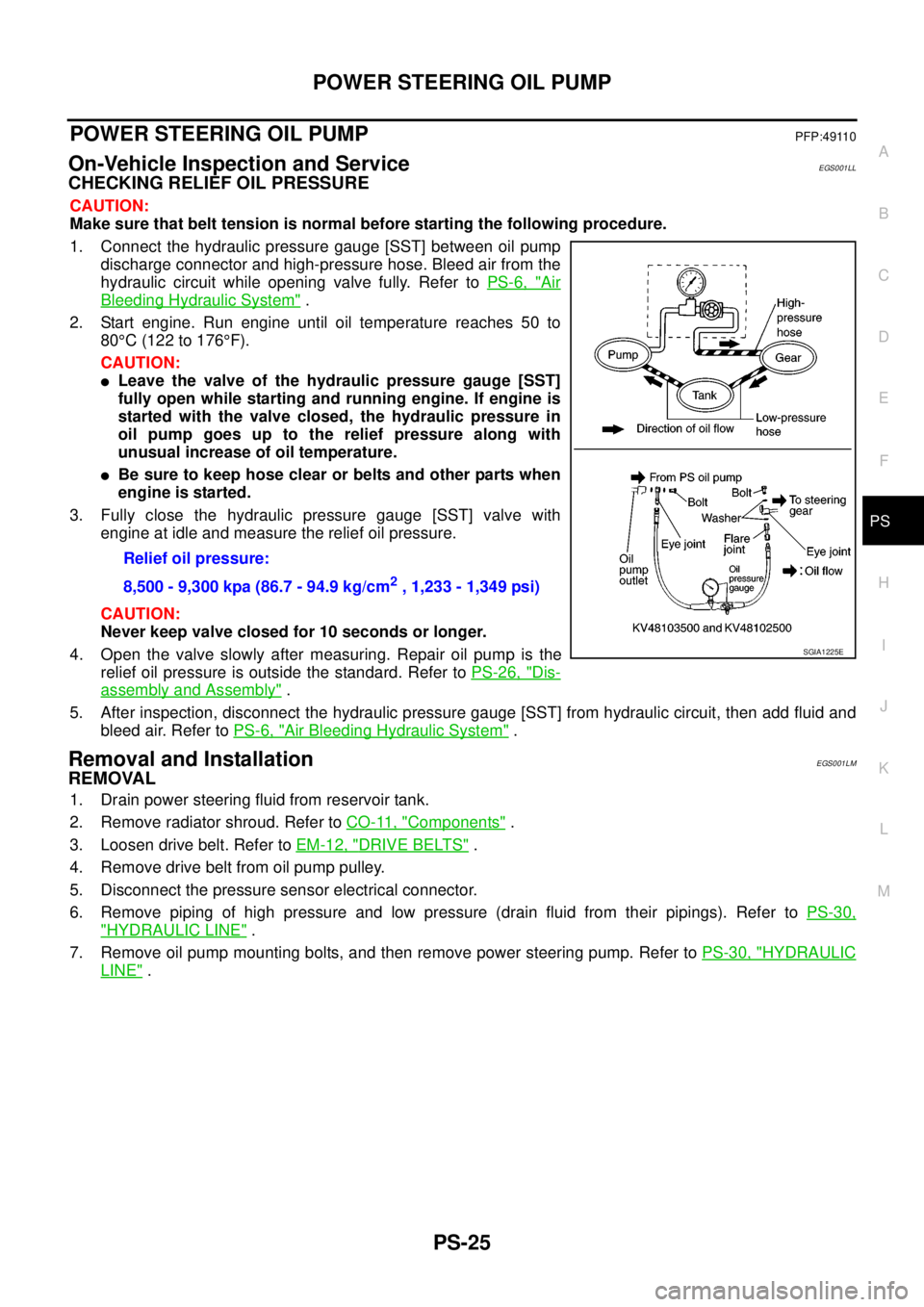
1. Connect the hydraulic pressure gauge [SST] between oil pump
discharge connector and high-pressure hose. Bleed air from the
hydraulic circuit while opening valve fully. Refer toPS-6, "
Air
Bleeding Hydraulic System".
2. Start engine. Run engine until oil temperature reaches 50 to
80°C(122to176°F).
CAUTION:
lLeave the valve of the hydraulic pressure gauge [SST]
fully open while starting and running engine. If engine is
started with the valve closed, the hydraulic pressure in
oil pump goes up to the relief pressure along with
unusual increase of oil temperature.
lBe sure to keep hose clear or belts and other parts when
engineisstarted.
3. Fully close the hydraulic pressure gauge [SST] valve with
engine at idle and measure the relief oil pressure.
CAUTION:
Never keep valve closed for 10 seconds or longer.
4. Open the valve slowly after measuring. Repair oil pump is the
relief oil pressure is outside the standard. Refer toPS-26, "
Dis-
assembly and Assembly".
5. After inspection, disconnect the hydraulic pressure gauge [SST] from hydraulic circuit, then add fluid and
bleed air. Refer toPS-6, "
Air Bleeding Hydraulic System".
Removal and InstallationEGS001LM
REMOVAL
1. Drain power steering fluid from reservoir tank.
2. Remove radiator shroud. Refer toCO-11, "
Components".
3. Loosen drive belt. Refer toEM-12, "
DRIVE BELTS".
4. Remove drive belt from oil pump pulley.
5. Disconnect the pressure sensor electrical connector.
6. Remove piping of high pressure and low pressure (drain fluid from their pipings). Refer toPS-30,
"HYDRAULIC LINE".
7. Remove oil pump mounting bolts, and then remove power steering pump. Refer toPS-30, "
HYDRAULIC
LINE". Relief oil pressure:
8,500 - 9,300 kpa (86.7 - 94.9 kg/cm
2, 1,233 - 1,349 psi)
SGIA1225E
Page 2946 of 3171

DRIVER AIR BAG MODULE
SRS-37
C
D
E
F
G
I
J
K
L
MA
B
SRS
4. Disconnect the driver air bag module and horn connectors, then remove the driver air bag module.
lFor removal/installation of the direct-connect SRS connectors, refer toSRS-8, "Direct-Connect SRS
Component Connectors".
CAUTION:
lWhen servicing the SRS, do not work from directly in front of air bag module.
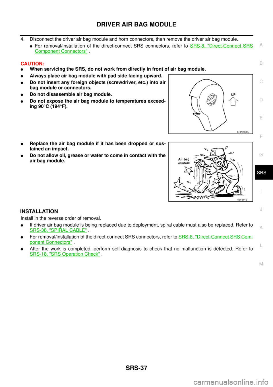
lAlways place air bag module with pad side facing upward.
lDo not insert any foreign objects (screwdriver, etc.) into air
bag module or connectors.
lDo not disassemble air bag module.
lDo not expose the air bag module to temperatures exceed-
ing 90°C(194°F).
lReplace the air bag module if it has been dropped or sus-
tainedanimpact.
lDo not allow oil, grease or water to come in contact with the
air bag module.
INSTALLATION
Install in the reverse order of removal.
lIf driver air bag module is being replaced due to deployment, spiral cable must also be replaced. Refer to
SRS-38, "
SPIRAL CABLE".
lFor removal/installation of the direct-connect SRS connectors, refer toSRS-8, "Direct-Connect SRS Com-
ponent Connectors".
lAfter the work is completed, perform self-diagnosis to check that no malfunction is detected. Refer to
SRS-18, "
SRS Operation Check".
LHIA0086E
SBF814E
Page 2952 of 3171

FRONT SIDE AIR BAG MODULE
SRS-43
C
D
E
F
G
I
J
K
L
MA
B
SRS
FRONT SIDE AIR BAG MODULEPFP:K8EH0
Removal and InstallationEHS001XV
REMOVAL
WARNING:
Removal of front side air bag module should only be done to allow deployment of front side air bag
module prior to disposal of seatback assembly.
Only complete seatback assemblies can be replaced. Refer toSE-26, "
SEATBACK (POWER AND MAN-
UAL SEAT)"andSE-27, "SEATBACK (FRAT FOLD SEAT)".
CAUTION:
lBefore servicing the SRS, turn the ignition switch off, disconnect both battery cables and wait at
least 3 minutes.
lWhen servicing the SRS, do not work from directly in front of air bag module.
1. Remove the front seat. Refer toSE-23, "
REMOVAL".
2. Remove the seatback trim and pad. Refer toSE-26, "
SEATBACK (POWER AND MANUAL SEAT)"and
SE-27, "
SEATBACK (FRAT FOLD SEAT)".
3. Remove the seatback rear finisher and remove the retainers securing the seat cushion trim. Refer toSE-
24, "SEAT CUSHION (POWER SEAT)"andSE-25, "SEAT CUSHION (MANUAL SEAT)".
4. Remove air bag module harness clips.
5. Remove the fasteners from the front side air bag module and remove the front side air bag module.
CAUTION:
lWhen using a clip removal tool to remove the seatback
board, take care not to damage the harness for front side air
bag module.
lWhen servicing the SRS, do not work from directly in front
of air bag module.
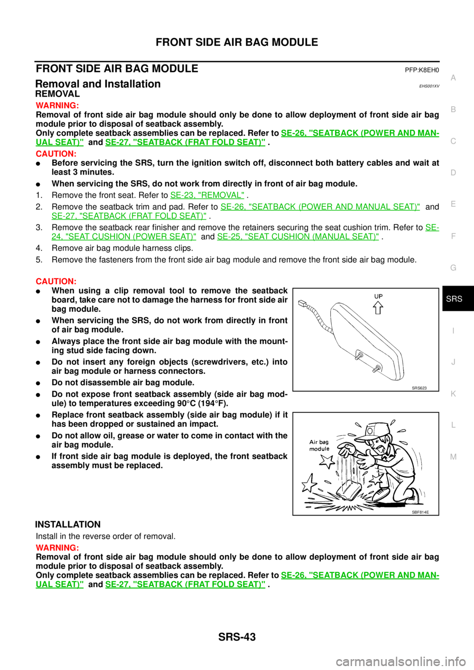
lAlways place the front side air bag module with the mount-
ing stud side facing down.
lDo not insert any foreign objects (screwdrivers, etc.) into
air bag module or harness connectors.
lDo not disassemble air bag module.
lDo not expose front seatback assembly (side air bag mod-
ule) to temperatures exceeding 90°C(194°F).
lReplace front seatback assembly (side air bag module) if it
has been dropped or sustained an impact.
lDo not allow oil, grease or water to come in contact with the
air bag module.
lIf front side air bag module is deployed, the front seatback
assembly must be replaced.
INSTALLATION
Install in the reverse order of removal.
WARNING:
Removal of front side air bag module should only be done to allow deployment of front side air bag
module prior to disposal of seatback assembly.
Only complete seatback assemblies can be replaced. Refer toSE-26, "
SEATBACK (POWER AND MAN-
UAL SEAT)"andSE-27, "SEATBACK (FRAT FOLD SEAT)".
SRS623
SBF814E
Page 2953 of 3171

SRS-44
SIDE CURTAIN AIR BAG MODULE
SIDE CURTAIN AIR BAG MODULE
PFP:985P0
Removal and InstallationEHS001XW
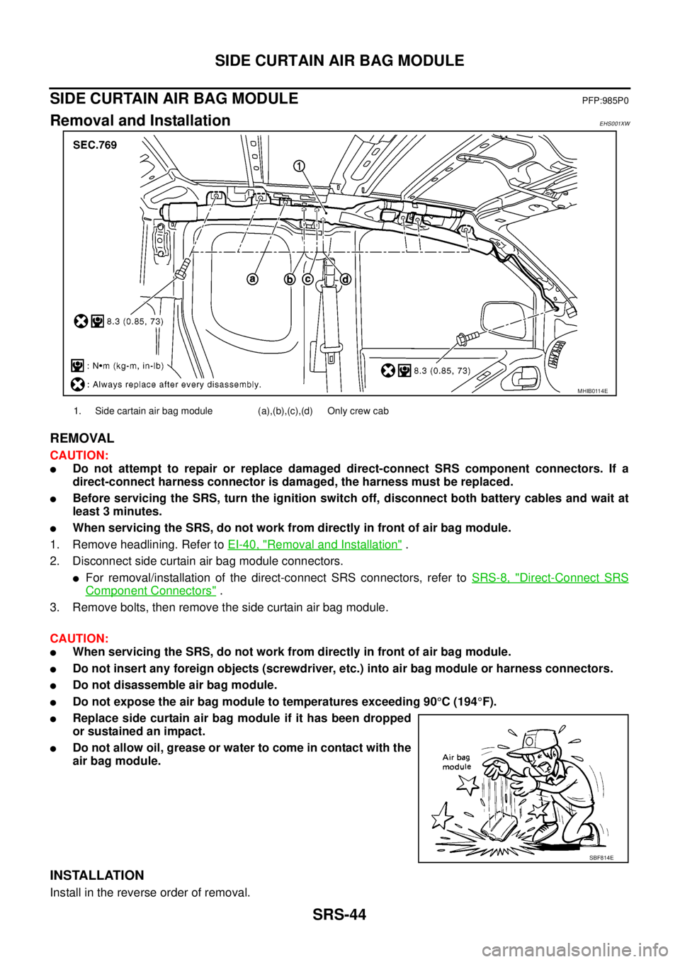
REMOVAL
CAUTION:
lDo not attempt to repair or replace damaged direct-connect SRS component connectors. If a
direct-connect harness connector is damaged, the harness must be replaced.
lBefore servicing the SRS, turn the ignition switch off, disconnect both battery cables and wait at
least 3 minutes.
lWhen servicing the SRS, do not work from directly in front of air bag module.
1. Remove headlining. Refer toEI-40, "
Removal and Installation".
2. Disconnect side curtain air bag module connectors.
lFor removal/installation of the direct-connect SRS connectors, refer toSRS-8, "Direct-Connect SRS
Component Connectors".
3. Remove bolts, then remove the side curtain air bag module.
CAUTION:
lWhen servicing the SRS, do not work from directly in front of air bag module.
lDo not insert any foreign objects (screwdriver, etc.) into air bag module or harness connectors.
lDo not disassemble air bag module.
lDo not expose the air bag module to temperatures exceeding 90°C(194°F).
lReplace side curtain air bag module if it has been dropped
or sustained an impact.
lDo not allow oil, grease or water to come in contact with the
air bag module.
INSTALLATION
Install in the reverse order of removal.
MHIB0114E
1. Side cartain air bag module (a),(b),(c),(d) Only crew cab
SBF814E