battery NISSAN NAVARA 2005 Repair Workshop Manual
[x] Cancel search | Manufacturer: NISSAN, Model Year: 2005, Model line: NAVARA, Model: NISSAN NAVARA 2005Pages: 3171, PDF Size: 49.59 MB
Page 15 of 3171
PRECAUTIONS
AT-7
D
E
F
G
H
I
J
K
L
MA
B
AT
PRECAUTIONSPFP:00001
Precautions for Supplemental Restraint System (SRS) “AIR BAG” and “SEAT
BELT PRE-TENSIONER”
ECS00IPT
The Supplemental Restraint System such as “AIR BAG” and “SEAT BELT PRE-TENSIONER”, used along
with a front seat belt, helps to reduce the risk or severity of injury to the driver and front passenger for certain
types of collision. Information necessary to service the system safely is included in the SRS and SB section of
this Service Manual.
WARNING:
lTo avoid rendering the SRS inoperative, which could increase the risk of personal injury or death
in the event of a collision which would result in air bag inflation, all maintenance must be per-
formed by an authorized NISSAN/INFINITI dealer.
lImproper maintenance, including incorrect removal and installation of the SRS, can lead to per-
sonal injury caused by unintentional activation of the system. For removal of Spiral Cable and Air
Bag Module, see the SRS section.
lDo not use electrical test equipment on any circuit related to the SRS unless instructed to in this
Service Manual. SRS wiring harnesses can be identified by yellow and/or orange harnesses or
harness connectors.
PrecautionsECS00IPR
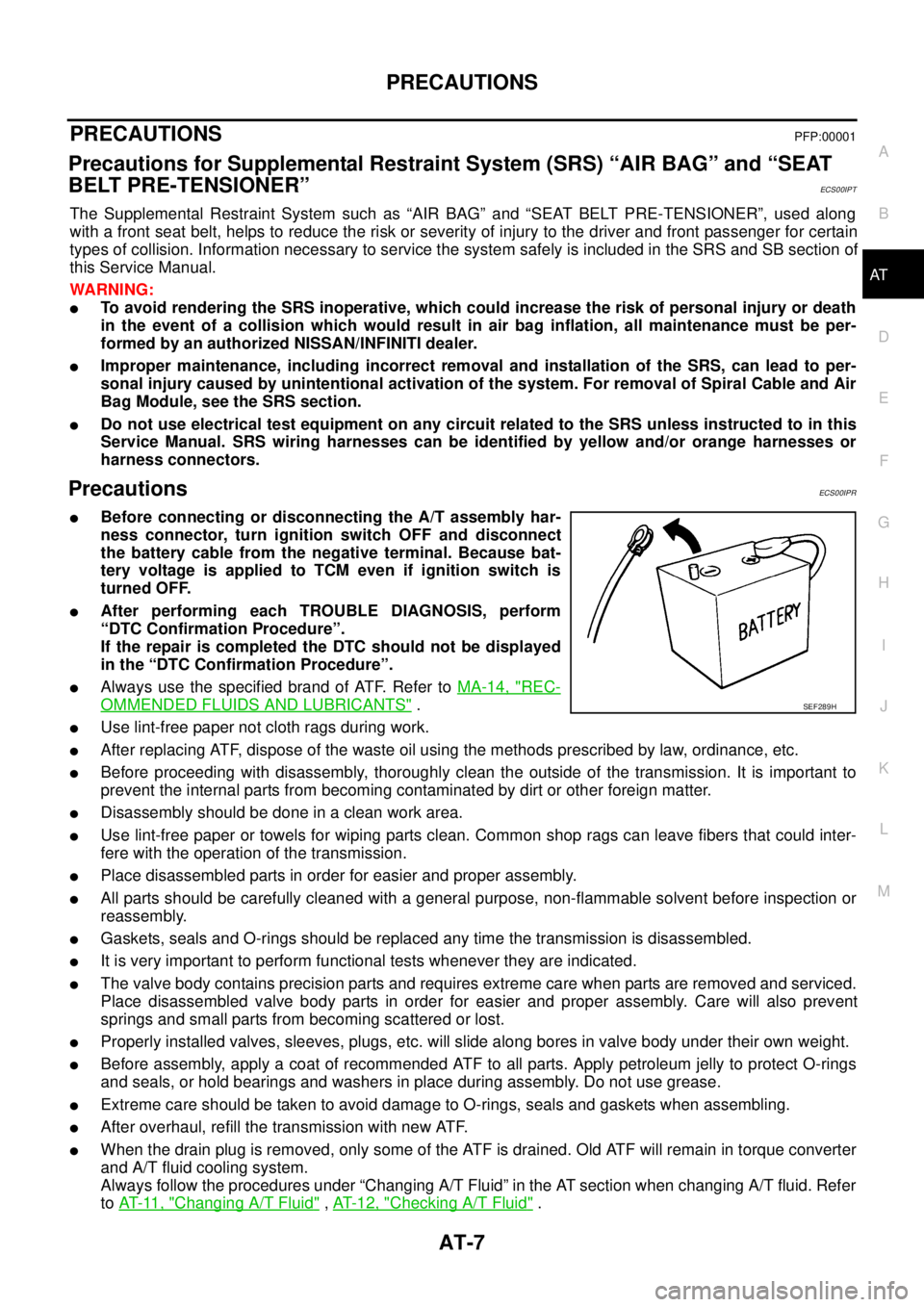
lBefore connecting or disconnecting the A/T assembly har-
ness connector, turn ignition switch OFF and disconnect
the battery cable from the negative terminal. Because bat-
tery voltage is applied to TCM even if ignition switch is
turned OFF.
lAfter performing each TROUBLE DIAGNOSIS, perform
“DTC Confirmation Procedure”.
If the repair is completed the DTC should not be displayed
in the “DTC Confirmation Procedure”.
lAlways use the specified brand of ATF. Refer toMA-14, "REC-
OMMENDED FLUIDS AND LUBRICANTS".
lUse lint-free paper not cloth rags during work.
lAfter replacing ATF, dispose of the waste oil using the methods prescribed by law, ordinance, etc.
lBefore proceeding with disassembly, thoroughly clean the outside of the transmission. It is important to
prevent the internal parts from becoming contaminated by dirt or other foreign matter.
lDisassembly should be done in a clean work area.
lUse lint-free paper or towels for wiping parts clean. Common shop rags can leave fibers that could inter-
fere with the operation of the transmission.
lPlace disassembled parts in order for easier and proper assembly.
lAll parts should be carefully cleaned with a general purpose, non-flammable solvent before inspection or
reassembly.
lGaskets, seals and O-rings should be replaced any time the transmission is disassembled.
lIt is very important to perform functional tests whenever they are indicated.
lThe valve body contains precision parts and requires extreme care when parts are removed and serviced.
Place disassembled valve body parts in order for easier and proper assembly. Care will also prevent
springs and small parts from becoming scattered or lost.
lProperly installed valves, sleeves, plugs, etc. will slide along bores in valve body under their own weight.
lBefore assembly, apply a coat of recommended ATF to all parts. Apply petroleum jelly to protect O-rings
and seals, or hold bearings and washers in place during assembly. Do not use grease.
lExtreme care should be taken to avoid damage to O-rings, seals and gaskets when assembling.
lAfter overhaul, refill the transmission with new ATF.
lWhen the drain plug is removed, only some of the ATF is drained. Old ATF will remain in torque converter
and A/T fluid cooling system.
Always follow the procedures under “Changing A/T Fluid” in the AT section when changing A/T fluid. Refer
toAT-11, "
Changing A/T Fluid",AT-12, "Checking A/T Fluid".
SEF289H
Page 84 of 3171
AT-76
TROUBLE DIAGNOSIS
TCM Input/Output Signal Reference Values
ECS00FX9
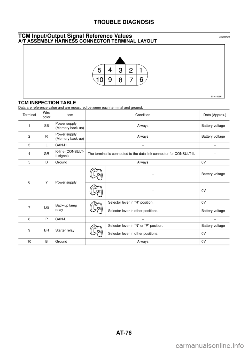
A/T ASSEMBLY HARNESS CONNECTOR TERMINAL LAYOUT
TCM INSPECTION TABLE
Data are reference value and are measured between each terminal and ground.
SCIA1658E
TerminalWire
colorItem Condition Data (Approx.)
1SBPower supply
(Memory back-up)Always Battery voltage
2RPower supply
(Memory back-up)Always Battery voltage
3 L CAN-H – –
4GRK-line (CONSULT-
II signal)The terminal is connected to the data link connector for CONSULT-II. –
5 B Ground Always 0V
6 Y Power supply– Battery voltage
–0V
7LGBack-up lamp
relaySelector lever in “R” position. 0V
Selector lever in other positions. Battery voltage
8 P CAN-L – –
9BRStarterrelaySelector lever in “N” or “P” position. Battery voltage
Selector lever in other positions. 0V
10 B Ground Always 0V
Page 91 of 3171
TROUBLE DIAGNOSIS
AT-83
D
E
F
G
H
I
J
K
L
MA
B
AT
DATA MONITOR MODE
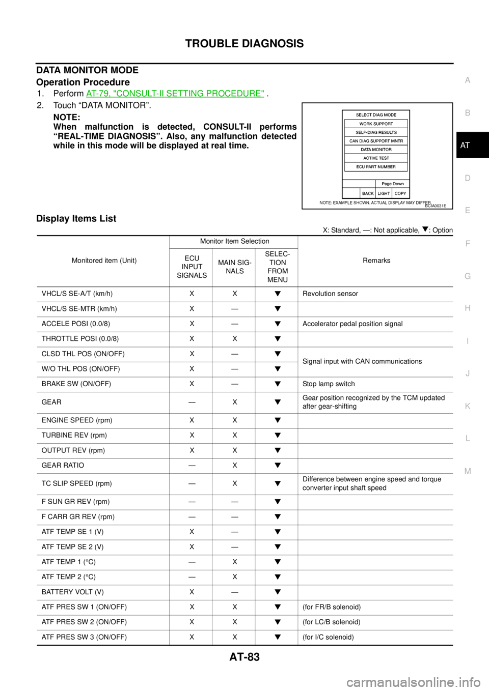
Operation Procedure
1. PerformAT-79, "CONSULT-II SETTING PROCEDURE".
2. Touch “DATA MONITOR”.
NOTE:
When malfunction is detected, CONSULT-II performs
“REAL-TIME DIAGNOSIS”. Also, any malfunction detected
while in this mode will be displayed at real time.
Display Items List
X: Standard, —: Not applicable, : Option
BCIA0031E
Monitored item (Unit)Monitor Item Selection
Remarks ECU
INPUT
SIGNALSMAIN SIG-
NALSSELEC-
TION
FROM
MENU
VHCL/S SE-A/T (km/h) X X Revolution sensor
VHCL/S SE-MTR (km/h) X —
ACCELE POSI (0.0/8) X — Accelerator pedal position signal
THROTTLE POSI (0.0/8) X X
CLSD THL POS (ON/OFF) X —
Signal input with CAN communications
W/O THL POS (ON/OFF) X —
BRAKE SW (ON/OFF) X — Stop lamp switch
GEAR — XGear position recognized by the TCM updated
after gear-shifting
ENGINE SPEED (rpm) X X
TURBINE REV (rpm) X X
OUTPUT REV (rpm) X X
GEAR RATIO — X
TC SLIP SPEED (rpm) — XDifference between engine speed and torque
converter input shaft speed
F SUN GR REV (rpm) — —
F CARR GR REV (rpm) — —
ATFTEMPSE1(V) X —
ATFTEMPSE2(V) X —
AT F T E M P 1 (°C) — X
AT F T E M P 2 (°C) — X
BATTERY VOLT (V) X —
ATF PRES SW 1 (ON/OFF) X X (for FR/B solenoid)
ATF PRES SW 2 (ON/OFF) X X (for LC/B solenoid)
ATF PRES SW 3 (ON/OFF) X X (for I/C solenoid)
Page 104 of 3171
AT-96
DTC P0615 START SIGNAL CIRCUIT
Data are reference value and are measured between each terminal and ground.
Diagnostic ProcedureECS00FXO
1.CHECK STARTER RELAY
With CONSULT-II
1. Turn ignition switch ON. (Do not start engine.)
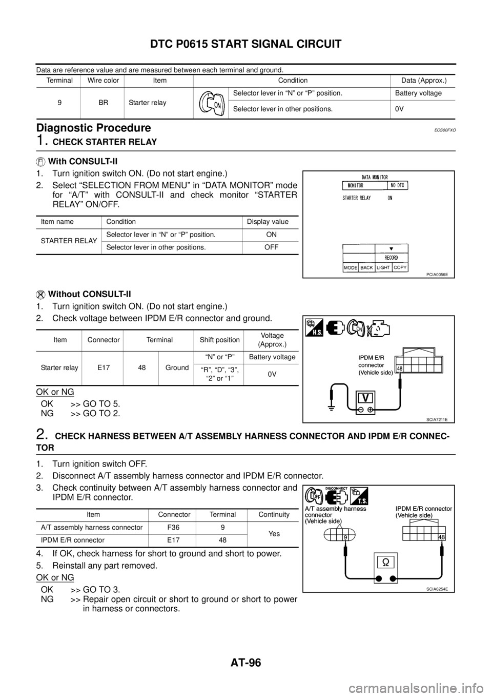
2. Select “SELECTION FROM MENU” in “DATA MONITOR” mode
for “A/T” with CONSULT-II and check monitor “STARTER
RELAY” ON/OFF.
Without CONSULT-II
1. Turn ignition switch ON. (Do not start engine.)
2. Check voltage between IPDM E/R connector and ground.
OK or NG
OK >> GO TO 5.
NG >> GO TO 2.
2.CHECK HARNESS BETWEEN A/T ASSEMBLY HARNESS CONNECTOR AND IPDM E/R CONNEC-
TOR
1. Turn ignition switch OFF.
2. Disconnect A/T assembly harness connector and IPDM E/R connector.
3. Check continuity between A/T assembly harness connector and
IPDM E/R connector.
4. If OK, check harness for short to ground and short to power.
5. Reinstall any part removed.
OK or NG
OK >> GO TO 3.
NG >> Repair open circuit or short to ground or short to power
in harness or connectors.
Terminal Wire color Item Condition Data (Approx.)
9BRStarterrelaySelector lever in “N” or “P” position. Battery voltage
Selector lever in other positions. 0V
Item name Condition Display value
STARTER RELAYSelector lever in “N” or “P” position. ON
Selector lever in other positions. OFF
PCIA0056E
Item Connector Terminal Shift positionVoltage
(Approx.)
Starter relay E17 48 Ground“N” or “P” Battery voltage
“R”, “D”, “3”,
“2”or“1”0V
SCIA7211E
Item Connector Terminal Continuity
A/T assembly harness connector F36 9
Ye s
IPDM E/R connector E17 48
SCIA6254E
Page 173 of 3171
MAIN POWER SUPPLY AND GROUND CIRCUIT
AT-165
D
E
F
G
H
I
J
K
L
MA
B
AT
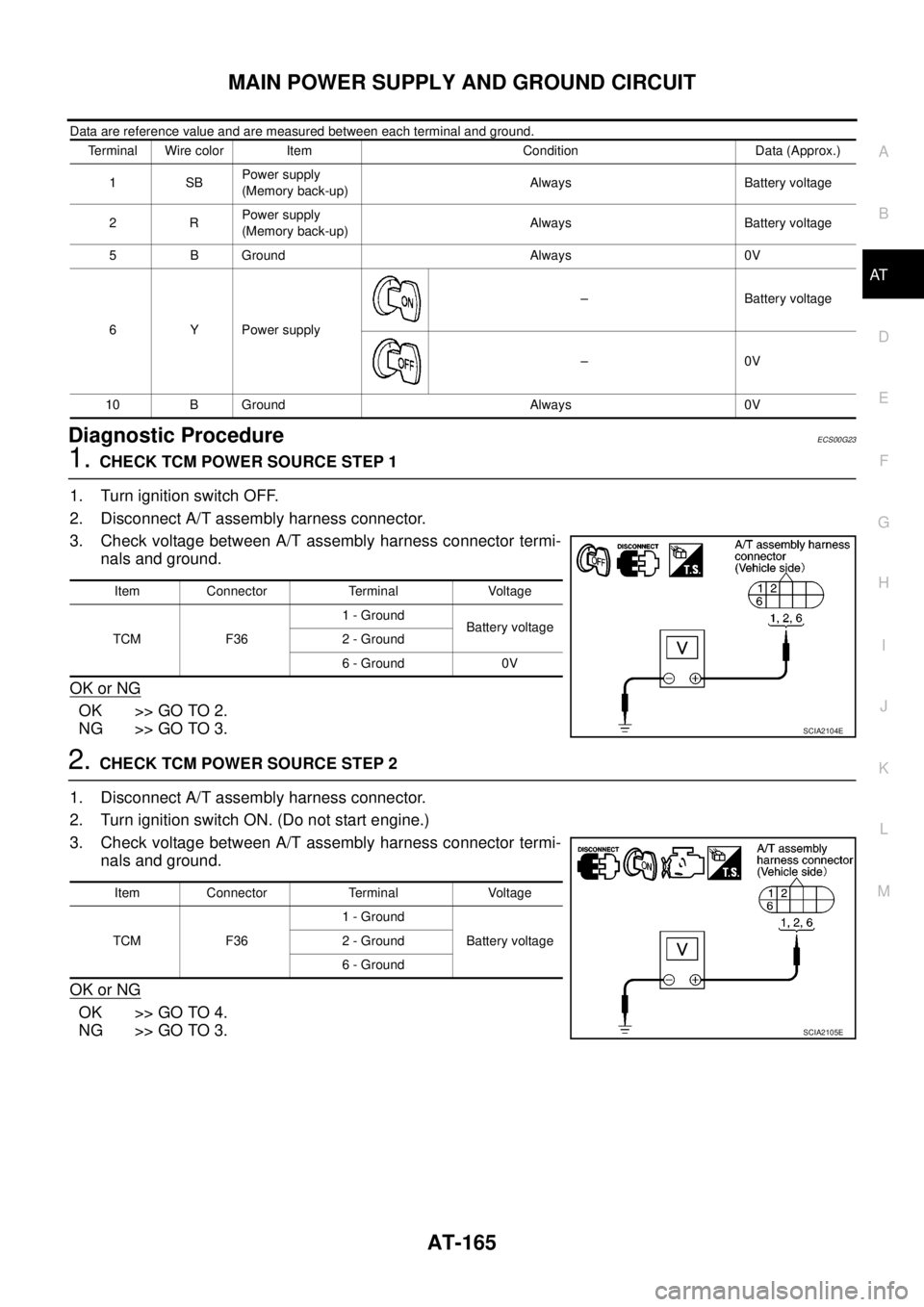
Data are reference value and are measured between each terminal and ground.
Diagnostic ProcedureECS00G23
1.CHECK TCM POWER SOURCE STEP 1
1. Turn ignition switch OFF.
2. Disconnect A/T assembly harness connector.
3. Check voltage between A/T assembly harness connector termi-
nals and ground.
OK or NG
OK >> GO TO 2.
NG >> GO TO 3.
2.CHECK TCM POWER SOURCE STEP 2
1. Disconnect A/T assembly harness connector.
2. Turn ignition switch ON. (Do not start engine.)
3. Check voltage between A/T assembly harness connector termi-
nals and ground.
OK or NG
OK >> GO TO 4.
NG >> GO TO 3.
Terminal Wire color Item Condition Data (Approx.)
1SBPower supply
(Memory back-up)Always Battery voltage
2RPower supply
(Memory back-up)Always Battery voltage
5 B Ground Always 0V
6 Y Power supply– Battery voltage
–0V
10 B Ground Always 0V
Item Connector Terminal Voltage
TCM F361 - Ground
Battery voltage
2 - Ground
6 - Ground 0V
SCIA2104E
Item Connector Terminal Voltage
TCM F361 - Ground
Battery voltage 2 - Ground
6 - Ground
SCIA2105E
Page 174 of 3171
AT-166
MAIN POWER SUPPLY AND GROUND CIRCUIT
3.DETECT MALFUNCTIONING ITEM
Check the following.
lHarness for short or open between battery and A/T assembly harness connector F36 terminals 1, 2
lHarness for short or open between ignition switch and A/T assembly harness connector F36 terminal 6
l10A fuse (No. 25, located in fuse and fusible link block) and 10A fuse (No. 49, located in IPDM E/R)
lIgnition switch, Refer toPG-4, "POWER SUPPLY ROUTING CIRCUIT".
OK or NG
OK >> GO TO 4.
NG >> Repair or replace damaged parts.
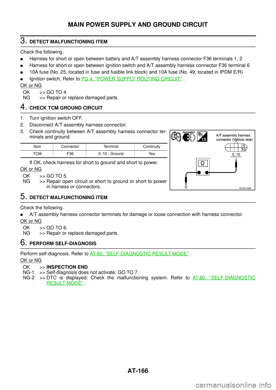
4.CHECK TCM GROUND CIRCUIT
1. Turn ignition switch OFF.
2. Disconnect A/T assembly harness connector.
3. Check continuity between A/T assembly harness connector ter-
minals and ground.
If OK, check harness for short to ground and short to power.
OK or NG
OK >> GO TO 5.
NG >> Repair open circuit or short to ground or short to power
in harness or connectors.
5.DETECT MALFUNCTIONING ITEM
Check the following.
lA/T assembly harness connector terminals for damage or loose connection with harness connector.
OK or NG
OK >> GO TO 6.
NG >> Repair or replace damaged parts.
6.PERFORM SELF-DIAGNOSIS
Perform self-diagnosis. Refer toAT-80, "
SELF-DIAGNOSTIC RESULT MODE".
OK or NG
OK >>INSPECTION END
NG-1 >> Self-diagnosis does not activate: GO TO 7.
NG-2 >> DTC is displayed: Check the malfunctioning system. Refer toAT-80, "
SELF-DIAGNOSTIC
RESULT MODE".
Item Connector Terminal Continuity
TCM F36 5, 10 - Ground Yes
SCIA2106E
Page 177 of 3171
BRAKE SIGNAL CIRCUIT
AT-169
D
E
F
G
H
I
J
K
L
MA
B
AT
BRAKE SIGNAL CIRCUITPFP:25320
CONSULT-II Reference ValueECS00G26
Diagnostic ProcedureECS00G27
1.CHECK CAN COMMUNICATION LINE
Perform self-diagnosis. Refer toAT-80, "
SELF-DIAGNOSTIC RESULT MODE",AT-89, "Diagnostic Procedure
Without CONSULT-II".
Is a malfunction in the CAN communication indicated in the results?
YES >> Check CAN communication line. Refer toAT-91, "DTC U1000 CAN COMMUNICATION LINE".
NO >> GO TO 2.
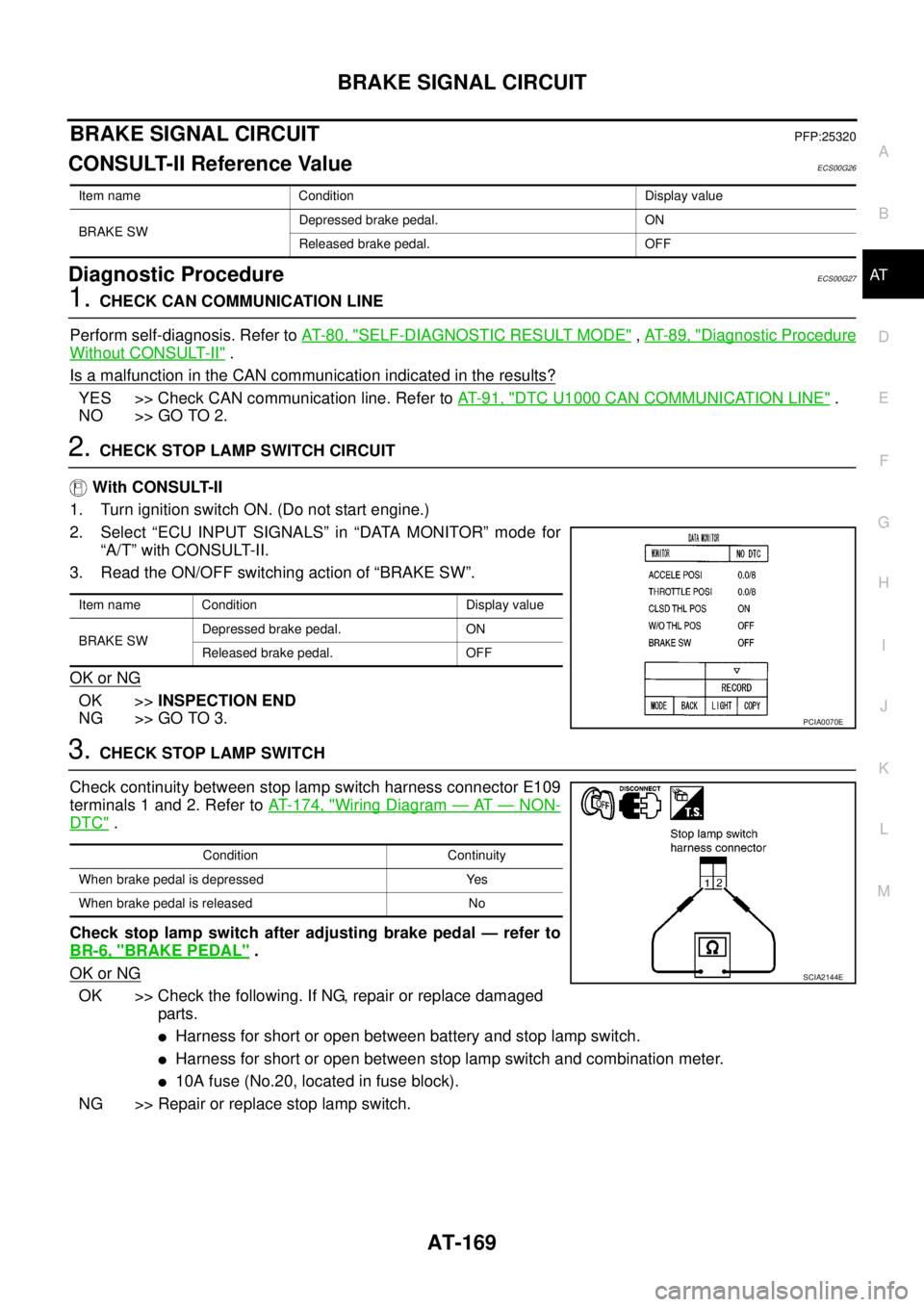
2.CHECK STOP LAMP SWITCH CIRCUIT
With CONSULT-II
1. Turn ignition switch ON. (Do not start engine.)
2. Select “ECU INPUT SIGNALS” in “DATA MONITOR” mode for
“A/T” with CONSULT-II.
3. Read the ON/OFF switching action of “BRAKE SW”.
OK or NG
OK >>INSPECTION END
NG >> GO TO 3.
3.CHECK STOP LAMP SWITCH
Check continuity between stop lamp switch harness connector E109
terminals 1 and 2. Refer toAT- 1 7 4 , "
Wiring Diagram—AT—NON-
DTC".
Check stop lamp switch after adjusting brake pedal — refer to
BR-6, "
BRAKE PEDAL".
OK or NG
OK >> Check the following. If NG, repair or replace damaged
parts.
lHarness for short or open between battery and stop lamp switch.
lHarness for short or open between stop lamp switch and combination meter.
l10A fuse (No.20, located in fuse block).
NG >> Repair or replace stop lamp switch.
Item name Condition Display value
BRAKE SWDepressed brake pedal. ON
Released brake pedal. OFF
Item name Condition Display value
BRAKE SWDepressed brake pedal. ON
Released brake pedal. OFF
PCIA0070E
Condition Continuity
When brake pedal is depressed Yes
When brake pedal is released No
SCIA2144E
Page 178 of 3171
AT-170
1ST POSITION SWITCH
1ST POSITION SWITCH
PFP:31918
CONSULT-II Reference ValueECS00I5W
Diagnostic ProcedureECS00I5X
1.CHECK CAN COMMUNICATION LINE
Perform the self-diagnosis. Refer toAT-80, "
SELF-DIAGNOSTIC RESULT MODE".
Is any malfunction in the CAN communication indicated in the results?
YES >> Check CAN communication line. Refer toAT-91, "DTC U1000 CAN COMMUNICATION LINE".
NO >> GO TO 2.
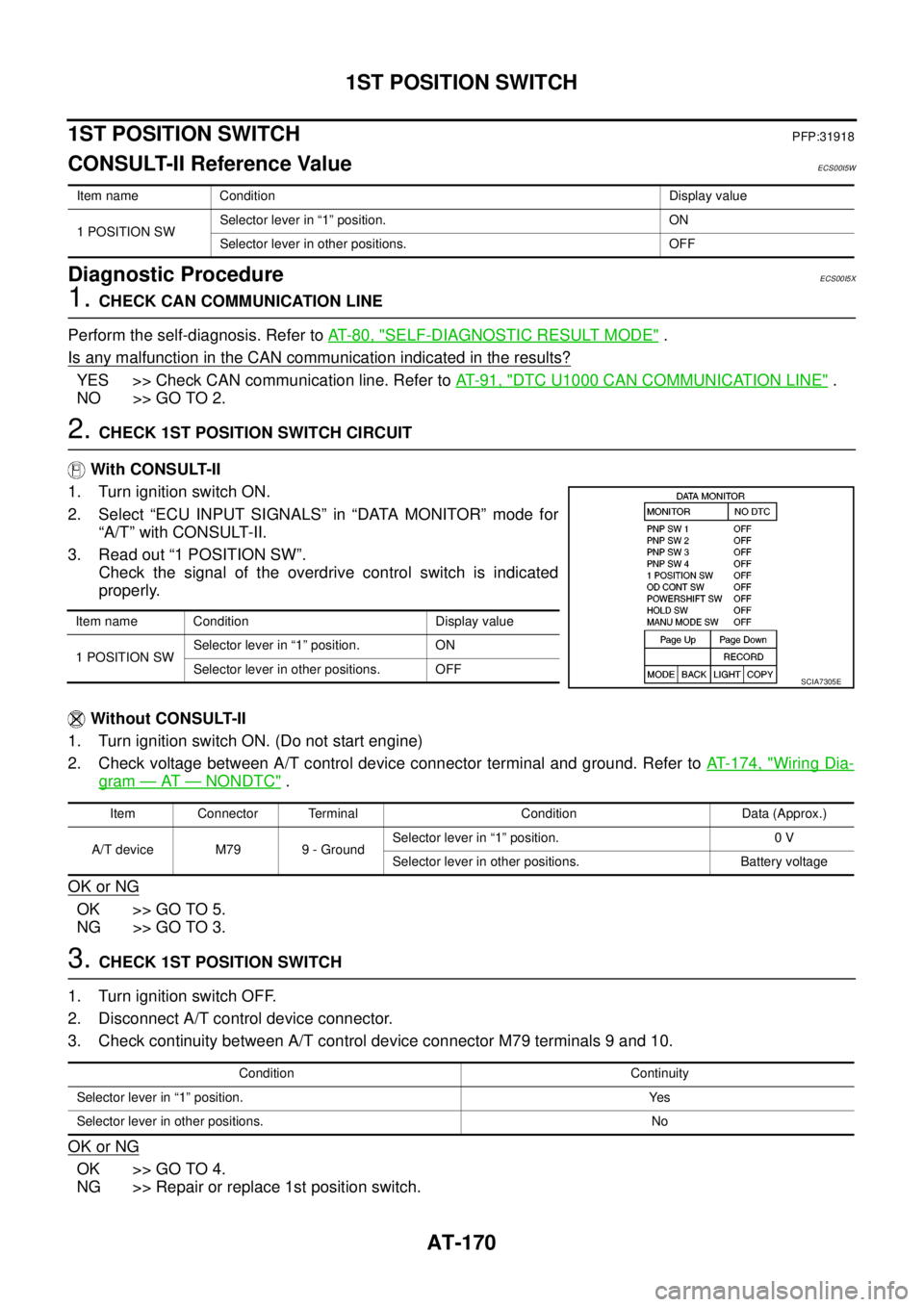
2.CHECK 1ST POSITION SWITCH CIRCUIT
With CONSULT-II
1. Turn ignition switch ON.
2. Select “ECU INPUT SIGNALS” in “DATA MONITOR” mode for
“A/T” with CONSULT-II.
3. Read out “1 POSITION SW”.
Check the signal of the overdrive control switch is indicated
properly.
Without CONSULT-II
1. Turn ignition switch ON. (Do not start engine)
2. Check voltage between A/T control device connector terminal and ground. Refer toAT- 1 7 4 , "
Wiring Dia-
gram—AT—NONDTC".
OK or NG
OK >> GO TO 5.
NG >> GO TO 3.
3.CHECK 1ST POSITION SWITCH
1. Turn ignition switch OFF.
2. Disconnect A/T control device connector.
3. Check continuity between A/T control device connector M79 terminals 9 and 10.
OK or NG
OK >> GO TO 4.
NG >> Repair or replace 1st position switch.
Item name Condition Display value
1 POSITION SWSelector lever in “1” position. ON
Selector lever in other positions. OFF
Item name Condition Display value
1 POSITION SWSelector lever in “1” position. ON
Selector lever in other positions. OFF
SCIA7305E
Item Connector Terminal Condition Data (Approx.)
A/T device M79 9 - GroundSelector lever in “1” position. 0 V
Selector lever in other positions. Battery voltage
Condition Continuity
Selector lever in “1” position. Yes
Selector lever in other positions. No
Page 180 of 3171
AT-172
OVERDRIVE CONTROL SWITCH
OVERDRIVE CONTROL SWITCH
PFP:25130
CONSULT-II Reference ValueECS00HQY
Diagnostic ProcedureECS00HQZ
1.CHECK CAN COMMUNICATION LINE
Perform the self-diagnosis. Refer toAT-80, "
SELF-DIAGNOSTIC RESULT MODE".
Is any malfunction in the CAN communication indicated in the results?
YES >> Check CAN communication line. Refer toAT-91, "DTC U1000 CAN COMMUNICATION LINE".
NO >> GO TO 2.
2.CHECK OVERDRIVE CONTOROL SWITCH CIRCUIT
With CONSULT-II
1. Turn ignition switch ON.
2. Select “ECU INPUT SIGNALS” in “DATA MONITOR” mode for
“A/T” with CONSULT-II.
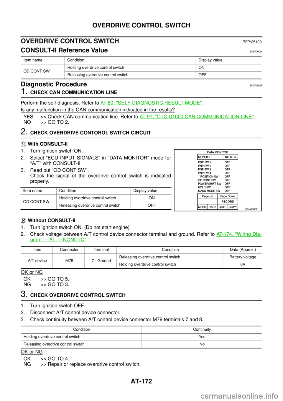
3. Read out “OD CONT SW”.
Check the signal of the overdrive control switch is indicated
properly.
Without CONSULT-II
1. Turn ignition switch ON. (Do not start engine)
2. Check voltage between A/T control device connector terminal and ground. Refer toAT- 1 7 4 , "
Wiring Dia-
gram—AT—NONDTC".
OK or NG
OK >> GO TO 5.
NG >> GO TO 3.
3.CHECK OVERDRIVE CONTROL SWITCH
1. Turn ignition switch OFF.
2. Disconnect A/T control device connector.
3. Check continuity between A/T control device connector M79 terminals 7 and 8.
OK or NG
OK >> GO TO 4.
NG >> Repair or replace overdrive control switch.
Item name Condition Display value
OD CONT SWHolding overdrive control switch ON
Releasing overdrive control switch OFF
Item name Condition Display value
OD CONT SWHolding overdrive control switch ON
Releasing overdrive control switch OFF
SCIA7305E
Item Connector Terminal Condition Data (Approx.)
A/T device M79 7 - GroundReleasing overdrive control switch Battery voltage
Holding overdrive control switch 0V
Condition Continuity
Holding overdrive control switch Yes
Releasing overdrive control switch No
Page 185 of 3171
TROUBLE DIAGNOSIS FOR SYMPTOMS
AT-177
D
E
F
G
H
I
J
K
L
MA
B
AT
Data are reference value and are measured between each terminal and ground.
OD OFF Indicator Lamp Does Not Come OnECS00G2B
SYMPTOM:
OD OFF indicator lamp does not come on for about 2 seconds when turning ignition switch ON.
DIAGNOSTIC PROCEDURE
1.CHECK CAN COMMUNICATION LINE
Perform self-diagnosis. Refer toAT-80, "
SELF-DIAGNOSTIC RESULT MODE",AT-89, "Diagnostic Procedure
Without CONSULT-II".
Is a malfunction in the CAN communication indicated in the results?
YES >> Check CAN communication line. Refer toAT-91, "DTC U1000 CAN COMMUNICATION LINE".
NO >> GO TO 2.
2.CHECK OD OFF INDICATOR LAMP CIRCUIT
Check combination meter. Refer toDI-4, "
COMBINATION METERS".
OK or NG
OK >> GO TO 3
NG >> Repair or replace damaged parts.
3.CHECK TCM POWER SUPPLY AND GROUND CIRCUIT
Check TCM power supply and ground circuit. Refer toAT- 1 6 4 , "
MAIN POWER SUPPLY AND GROUND CIR-
CUIT".
OK or NG
OK >>INSPECTION END
NG >> Repair or replace damaged parts.
Engine Cannot Be Started in “P” or “N” PositionECS00G2C
SYMPTOM:
lEngine cannot be started with selector lever in “P” or “N” position.
lEngine can be started with selector lever in “R”, “D”, “3”, “2” or “1” position.
DIAGNOSTIC PROCEDURE
1.CHECK SELF-DIAGNOSIS RESULTS
Perform self-diagnosis. Refer toAT-80, "
SELF-DIAGNOSTIC RESULT MODE",AT-89, "Diagnostic Procedure
Without CONSULT-II".
Do the self-diagnosis results indicate PNP switch?
YES >> Check malfunctioning system. Refer toAT-99, "DTC P0705 PARK/NEUTRAL POSITION
SWITCH".
NO >> GO TO 2.
TerminalWire
colorItem Condition Data (Approx.)
3 L CAN-H – –
4GRK-line (CONSULT-
II signal)The terminal is connected to the data link connector for CONSULT-II. –
7LGBack-up lamp
relaySelector lever in “R” position. 0V
Selector lever in other positions. Battery voltage
8 P CAN-L – –
9BRStarterrelaySelector lever in “N” or “P” position. Battery voltage
Selector lever in other positions. 0V