battery NISSAN NAVARA 2005 Repair User Guide
[x] Cancel search | Manufacturer: NISSAN, Model Year: 2005, Model line: NAVARA, Model: NISSAN NAVARA 2005Pages: 3171, PDF Size: 49.59 MB
Page 222 of 3171
AT-214
A/T SHIFT LOCK SYSTEM
Diagnostic Procedure
ECS00G32
SYMPTOM 1:
lSelector lever cannot be moved from “P” position with key in ON position and brake pedal
applied.
lSelector lever can be moved from “P” position with key in ON position and brake pedal released.
lSelector lever can be moved from “P” position when key is removed from key cylinder.
SYMPTOM 2:
lIgnition key cannot be removed when selector lever is set to “P” position.
lIgnition key can be removed when selector lever is set to any position except “P” position.
1.CHECK KEY INTERLOCK CABLE
Check key interlock cable for damage.
OK or NG
OK >> GO TO 2.
NG >> Repair or replace key interlock cable. Refer toAT- 2 1 6 , "
Removal and Installation".
2.CHECK SELECTOR LEVER POSITION
Check selector lever position for damage. Refer toAT- 2 11 , "
Checking of A/T Position"
OK or NG
OK >> GO TO 3.
NG >> Adjust control cable. Refer toAT- 2 11 , "
Adjustment of A/T Position".
3.CHECK SHIFT LOCK SOLENOID AND PARK POSITION SWITCH
1. Connect A/T device harness connector.
2. Turn ignition switch ON. (Do not start engine.)
3. Selector lever is set in “P” position.
4. Check operation.
OK or NG
OK >>INSPECTION END
NG >> GO TO 4.
4.CHECK POWER SOURCE
1. Turn ignition switch ON. (Do not start engine.)
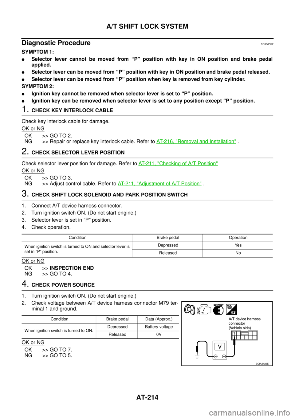
2. Check voltage between A/T device harness connector M79 ter-
minal 1 and ground.
OK or NG
OK >> GO TO 7.
NG >> GO TO 5.
Condition Brake pedal Operation
When ignition switch is turned to ON and selector lever is
set in “P” position.Depressed Yes
Released No
Condition Brake pedal Data (Approx.)
When ignition switch is turned to ON.Depressed Battery voltage
Released 0V
SCIA2122E
Page 227 of 3171
ON-VEHICLE SERVICE
AT-219
D
E
F
G
H
I
J
K
L
MA
B
AT
CONTROL VALVE WITH TCM REMOVAL AND INSTALLATION
Removal
1. Disconnect the battery cable from the negative terminal.
2. Remove under cover.
3. Drain ATF through drain hole.
4. Remove control cable from A/T assembly. Refer toAT- 2 1 0 , "
COMPONENTS".
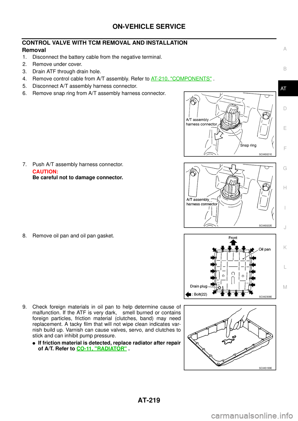
5. Disconnect A/T assembly harness connector.
6. Remove snap ring from A/T assembly harness connector.
7. Push A/T assembly harness connector.
CAUTION:
Be careful not to damage connector.
8. Remove oil pan and oil pan gasket.
9. Check foreign materials in oil pan to help determine cause of
malfunction. If the ATF is very dark, smell burned or contains
foreign particles, friction material (clutches, band) may need
replacement. A tacky film that will not wipe clean indicates var-
nish build up. Varnish can cause valves, servo, and clutches to
stick and can inhibit pump pressure.
lIf friction material is detected, replace radiator after repair
of A/T. Refer toCO-11, "
RADIATOR".
SCIA5021E
SCIA5022E
SCIA2308E
SCIA5199E
Page 234 of 3171
AT-226
ON-VEHICLE SERVICE
15. Install oil pan to transmission case.
a. Install oil pan gasket to oil pan.
CAUTION:
lDo not reuse oil pan gasket.
lInstall it in the direction to align hole positions.
lCompletely remove all moisture, oil and old gasket, etc. from oil pan gasket mounting surface.
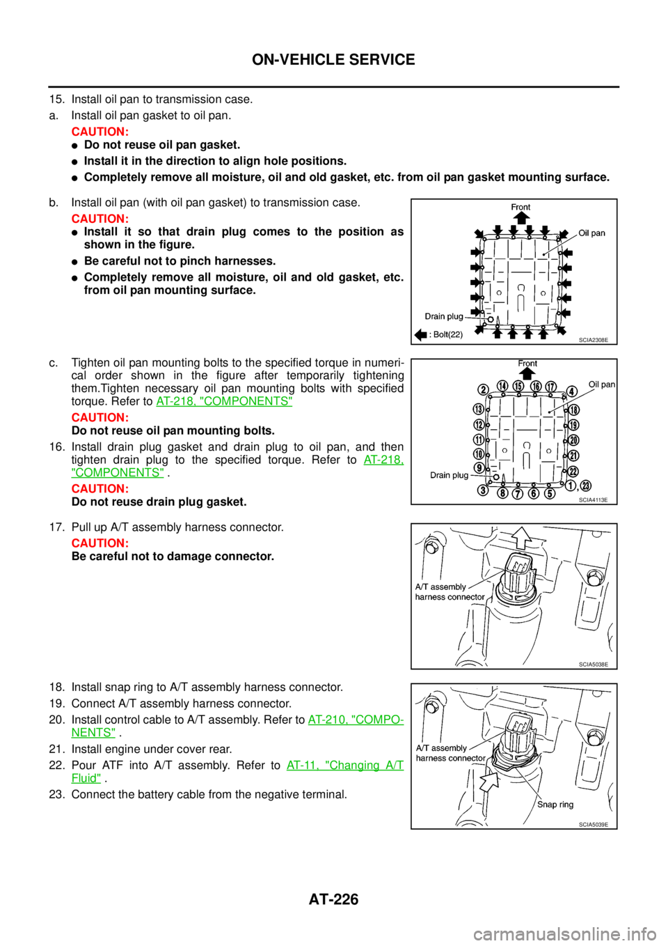
b. Install oil pan (with oil pan gasket) to transmission case.
CAUTION:
lInstall it so that drain plug comes to the position as
shown in the figure.
lBe careful not to pinch harnesses.
lCompletely remove all moisture, oil and old gasket, etc.
from oil pan mounting surface.
c. Tighten oil pan mounting bolts to the specified torque in numeri-
cal order shown in the figure after temporarily tightening
them.Tighten necessary oil pan mounting bolts with specified
torque. Refer toAT- 2 1 8 , "
COMPONENTS"
CAUTION:
Do not reuse oil pan mounting bolts.
16. Install drain plug gasket and drain plug to oil pan, and then
tighten drain plug to the specified torque. Refer toAT-218,
"COMPONENTS".
CAUTION:
Do not reuse drain plug gasket.
17. Pull up A/T assembly harness connector.
CAUTION:
Be careful not to damage connector.
18. Install snap ring to A/T assembly harness connector.
19. Connect A/T assembly harness connector.
20. Install control cable to A/T assembly. Refer toAT- 2 1 0 , "
COMPO-
NENTS".
21. Install engine under cover rear.
22. Pour ATF into A/T assembly. Refer toAT-11, "
Changing A/T
Fluid".
23. Connect the battery cable from the negative terminal.
SCIA2308E
SCIA4113E
SCIA5038E
SCIA5039E
Page 235 of 3171
ON-VEHICLE SERVICE
AT-227
D
E
F
G
H
I
J
K
L
MA
B
AT
A/T FLUID TEMPERATURE SENSOR 2 REMOVAL AND INSTALLATION
Removal
1. Disconnect the battery cable from the negative terminal.
2. Remove under cover.
3. Drain ATF through drain hole.
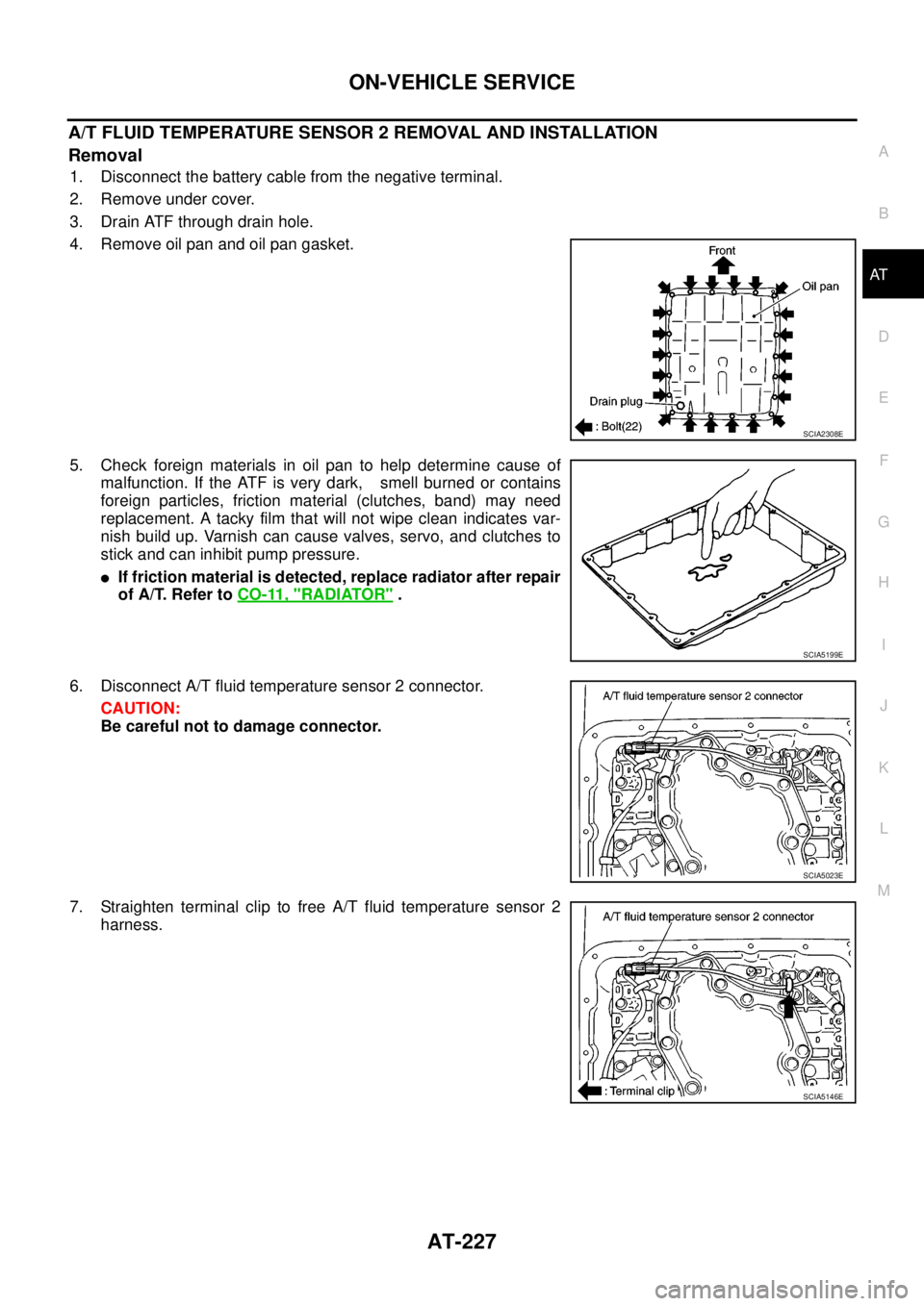
4. Remove oil pan and oil pan gasket.
5. Check foreign materials in oil pan to help determine cause of
malfunction. If the ATF is very dark, smell burned or contains
foreign particles, friction material (clutches, band) may need
replacement. A tacky film that will not wipe clean indicates var-
nish build up. Varnish can cause valves, servo, and clutches to
stick and can inhibit pump pressure.
lIf friction material is detected, replace radiator after repair
of A/T. Refer toCO-11, "
RADIATOR".
6. Disconnect A/T fluid temperature sensor 2 connector.
CAUTION:
Be careful not to damage connector.
7. Straighten terminal clip to free A/T fluid temperature sensor 2
harness.
SCIA2308E
SCIA5199E
SCIA5023E
SCIA5146E
Page 237 of 3171
ON-VEHICLE SERVICE
AT-229
D
E
F
G
H
I
J
K
L
MA
B
AT
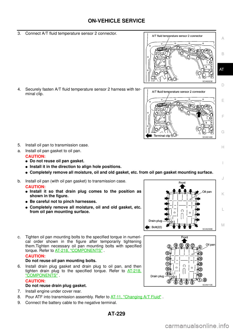
3. Connect A/T fluid temperature sensor 2 connector.
4. Securely fasten A/T fluid temperature sensor 2 harness with ter-
minal clip.
5. Install oil pan to transmission case.
a. Install oil pan gasket to oil pan.
CAUTION:
lDo not reuse oil pan gasket.
lInstall it in the direction to align hole positions.
lCompletely remove all moisture, oil and old gasket, etc. from oil pan gasket mounting surface.
b. Install oil pan (with oil pan gasket) to transmission case.
CAUTION:
lInstall it so that drain plug comes to the position as
shown in the figure.
lBe careful not to pinch harnesses.
lCompletely remove all moisture, oil and old gasket, etc.
from oil pan mounting surface.
c. Tighten oil pan mounting bolts to the specified torque in numeri-
cal order shown in the figure after temporarily tightening
them.Tighten necessary oil pan mounting bolts with specified
torque. Refer toAT- 2 1 8 , "
COMPONENTS".
CAUTION:
Do not reuse oil pan mounting bolts.
6. Install drain plug gasket and drain plug to oil pan, and then
tighten drain plug to the specified torque. Refer toAT-218,
"COMPONENTS".
CAUTION:
Do not reuse drain plug gasket.
7. Install engine under cover rear.
8. Pour ATF into transmission assembly. Refer toAT-11, "
Changing A/T Fluid".
9. Connect the battery cable to the negative terminal.
SCIA5023E
SCIA5146E
SCIA2308E
SCIA4113E
Page 246 of 3171
AT-238
ON-VEHICLE SERVICE
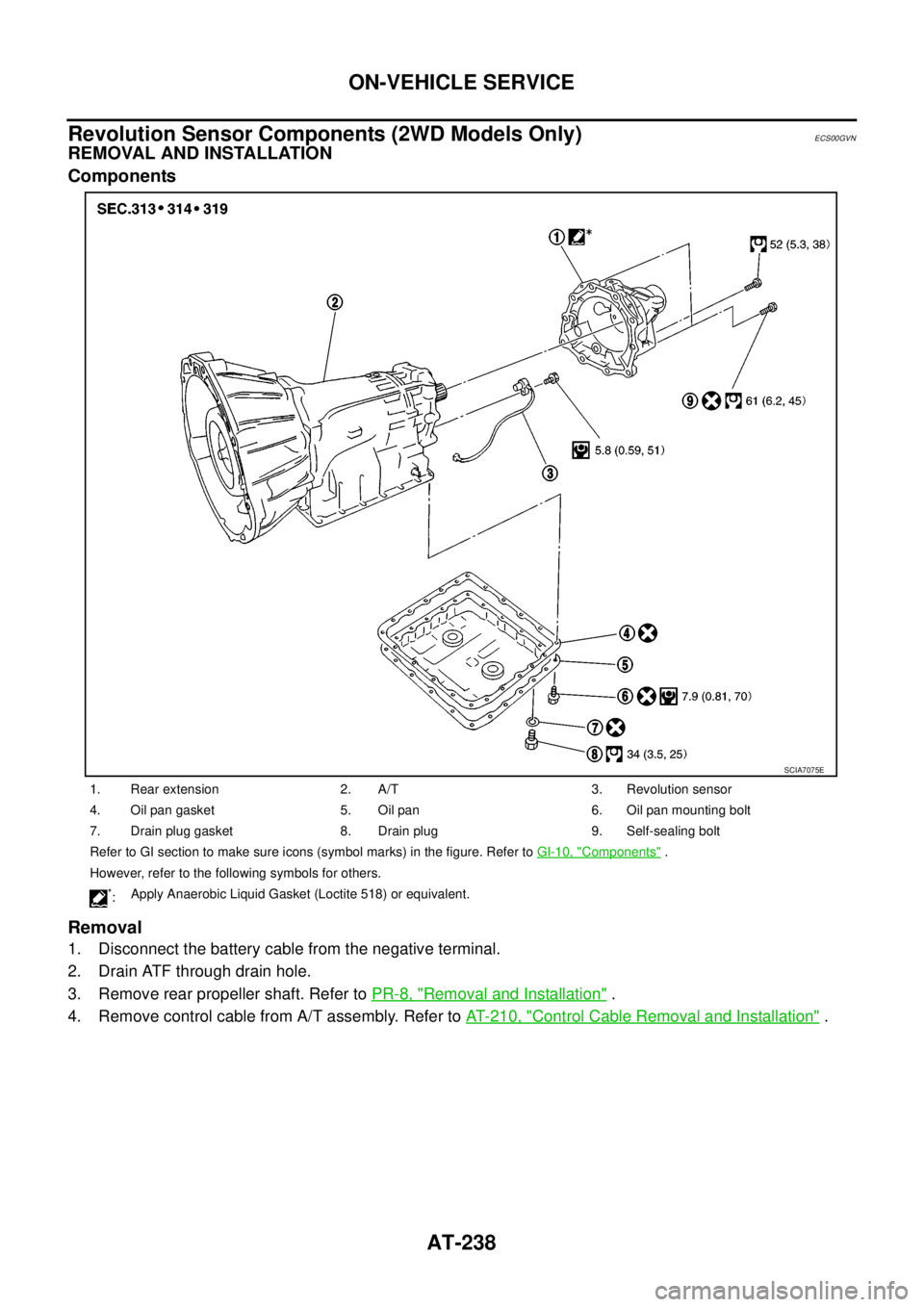
Revolution Sensor Components (2WD Models Only)
ECS00GVN
REMOVAL AND INSTALLATION
Components
Removal
1. Disconnect the battery cable from the negative terminal.
2. Drain ATF through drain hole.
3. Remove rear propeller shaft. Refer toPR-8, "
Removal and Installation".
4. Remove control cable from A/T assembly. Refer toAT- 2 1 0 , "
Control Cable Removal and Installation".
1. Rear extension 2. A/T 3. Revolution sensor
4. Oil pan gasket 5. Oil pan 6. Oil pan mounting bolt
7. Drain plug gasket 8. Drain plug 9. Self-sealing bolt
Refer to GI section to make sure icons (symbol marks) in the figure. Refer toGI-10, "
Components".
However, refer to the following symbols for others.
*:Apply Anaerobic Liquid Gasket (Loctite 518) or equivalent.
SCIA7075E
Page 250 of 3171
AT-242
ON-VEHICLE SERVICE
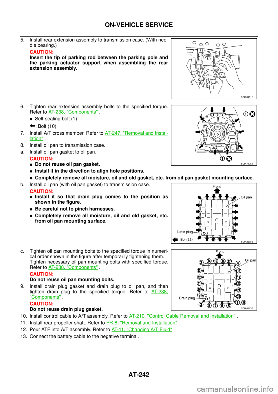
5. Install rear extension assembly to transmission case. (With nee-
dle bearing.)
CAUTION:
Insert the tip of parking rod between the parking pole and
the parking actuator support when assembling the rear
extension assembly.
6. Tighten rear extension assembly bolts to the specified torque.
Refer toAT- 2 3 8 , "
Components".
lSelf-sealing bolt (1)
:Bolt(10)
7. Install A/T cross member. Refer toAT- 2 4 7 , "
Removal and Instal-
lation".
8. Install oil pan to transmission case.
a. Install oil pan gasket to oil pan.
CAUTION:
lDo not reuse oil pan gasket.
lInstall it in the direction to align hole positions.
lCompletely remove all moisture, oil and old gasket, etc. from oil pan gasket mounting surface.
b. Install oil pan (with oil pan gasket) to transmission case.
CAUTION:
lInstall it so that drain plug comes to the position as
shown in the figure.
lBe careful not to pinch harnesses.
lCompletely remove all moisture, oil and old gasket, etc.
from oil pan mounting surface.
c. Tighten oil pan mounting bolts to the specified torque in numeri-
cal order shown in the figure after temporarily tightening them.
Tighten necessary oil pan mounting bolts with specified torque.
Refer toAT- 2 3 8 , "
Components".
CAUTION:
Do not reuse oil pan mounting bolts.
9. Install drain plug gasket and drain plug to oil pan, and then
tighten drain plug to the specified torque. Refer toAT-238,
"Components".
CAUTION:
Do not reuse drain plug gasket.
10. Install control cable to A/T assembly. Refer toAT- 2 1 0 , "
Control Cable Removal and Installation".
11. Install rear propeller shaft. Refer toPR-8, "
Removal and Installation".
12. Pour ATF into A/T assembly. Refer toAT-11, "
Changing A/T Fluid".
13. Connect the battery cable to the negative terminal.
SCIA3431E
SCIA7176J
SCIA2308E
SCIA4113E
Page 256 of 3171
AT-248
TRANSMISSION ASSEMBLY
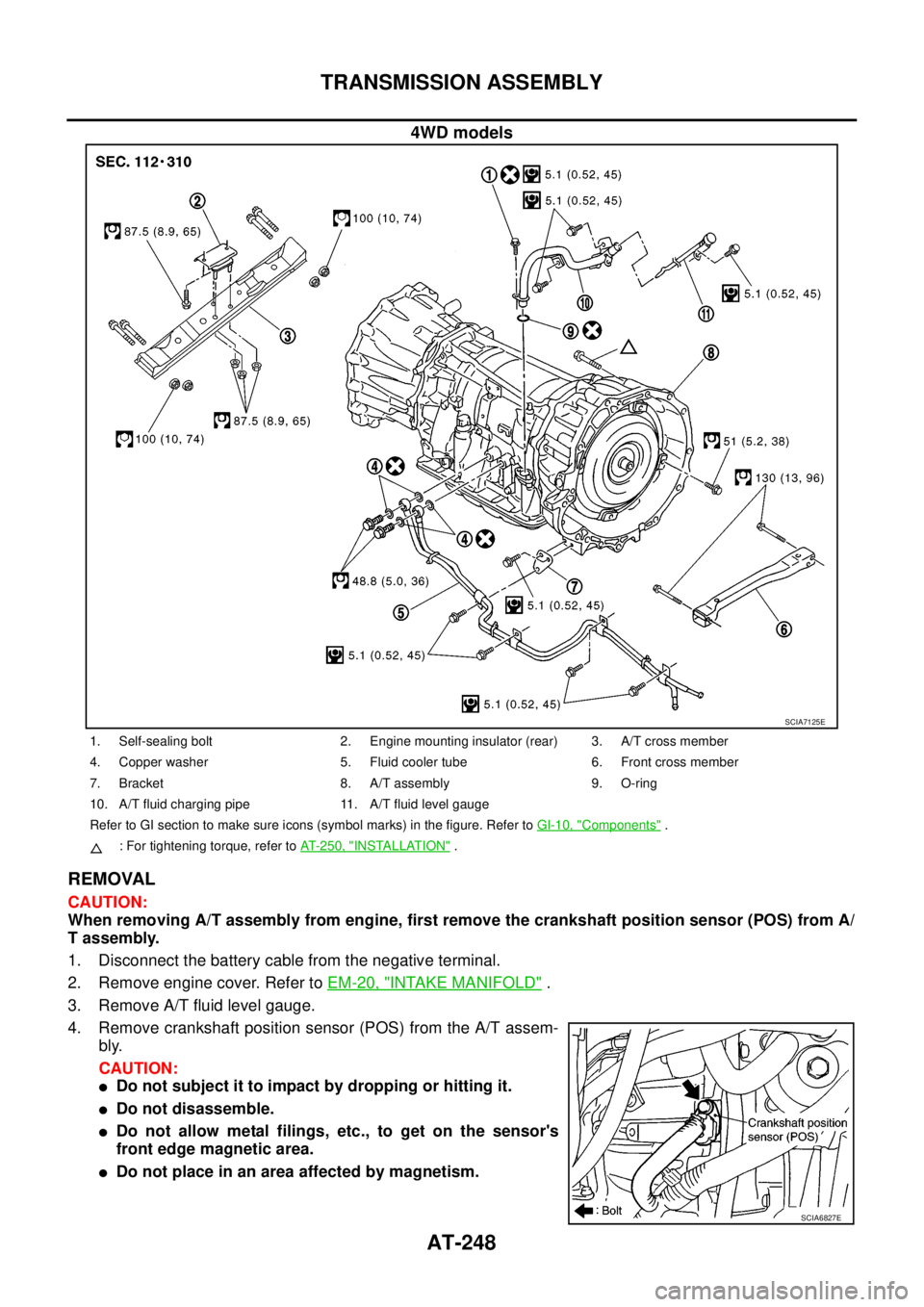
4WD models
REMOVAL
CAUTION:
When removing A/T assembly from engine, first remove the crankshaft position sensor (POS) from A/
T assembly.
1. Disconnect the battery cable from the negative terminal.
2. Remove engine cover. Refer toEM-20, "
INTAKE MANIFOLD".
3. Remove A/T fluid level gauge.
4. Remove crankshaft position sensor (POS) from the A/T assem-
bly.
CAUTION:
lDo not subject it to impact by dropping or hitting it.
lDo not disassemble.
lDo not allow metal filings, etc., to get on the sensor's
front edge magnetic area.
lDo not place in an area affected by magnetism.
SCIA7125E
1. Self-sealing bolt 2. Engine mounting insulator (rear) 3. A/T cross member
4. Copper washer 5. Fluid cooler tube 6. Front cross member
7. Bracket 8. A/T assembly 9. O-ring
10. A/T fluid charging pipe 11. A/T fluid level gauge
Refer to GI section to make sure icons (symbol marks) in the figure. Refer toGI-10, "
Components".
: For tightening torque, refer toAT-250, "
INSTALLATION".
SCIA6827E
Page 351 of 3171
PREPARATION
ATC-17
C
D
E
F
G
H
I
K
L
MA
B
AT C
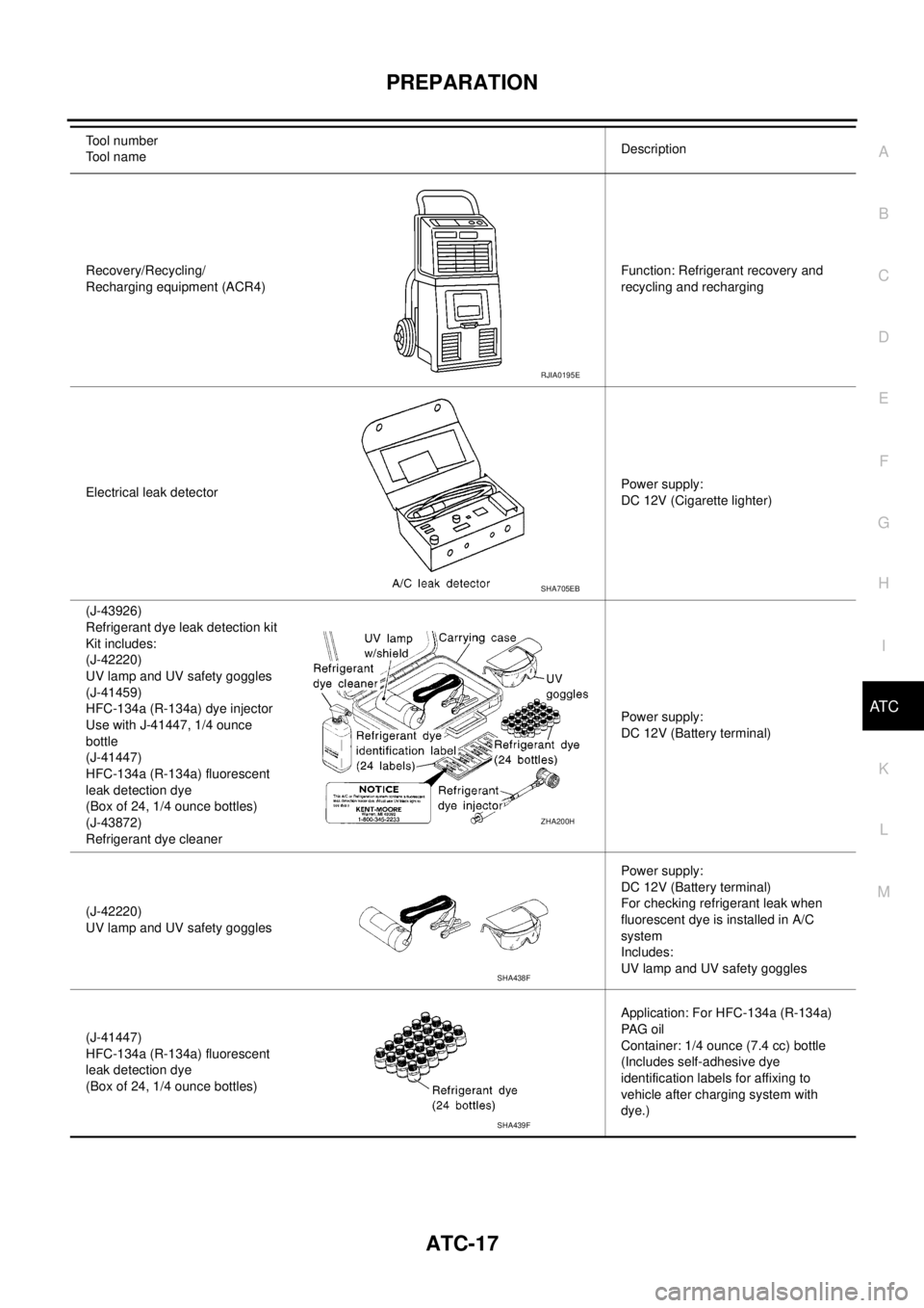
Recovery/Recycling/
Recharging equipment (ACR4)Function: Refrigerant recovery and
recycling and recharging
Electrical leak detectorPower supply:
DC 12V (Cigarette lighter)
(J-43926)
Refrigerant dye leak detection kit
Kit includes:
(J-42220)
UV lamp and UV safety goggles
(J-41459)
HFC-134a (R-134a) dye injector
Use with J-41447, 1/4 ounce
bottle
(J-41447)
HFC-134a (R-134a) fluorescent
leak detection dye
(Box of 24, 1/4 ounce bottles)
(J-43872)
Refrigerant dye cleanerPower supply:
DC 12V (Battery terminal)
(J-42220)
UV lamp and UV safety gogglesPower supply:
DC 12V (Battery terminal)
For checking refrigerant leak when
fluorescent dye is installed in A/C
system
Includes:
UV lamp and UV safety goggles
(J-41447)
HFC-134a (R-134a) fluorescent
leak detection dye
(Box of 24, 1/4 ounce bottles)Application: For HFC-134a (R-134a)
PA G o i l
Container: 1/4 ounce (7.4 cc) bottle
(Includes self-adhesive dye
identification labels for affixing to
vehicle after charging system with
dye.) Tool number
Tool nameDescription
RJIA0195E
SHA705EB
ZHA200H
SHA438F
SHA439F
Page 387 of 3171
TROUBLE DIAGNOSIS
ATC-53
C
D
E
F
G
H
I
K
L
MA
B
AT C
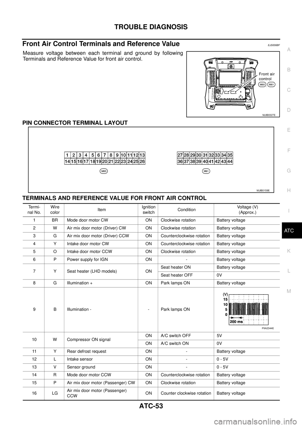
Front Air Control Terminals and Reference ValueEJS006BF
Measure voltage between each terminal and ground by following
Terminals and Reference Value for front air control.
PIN CONNECTOR TERMINAL LAYOUT
TERMINALS AND REFERENCE VALUE FOR FRONT AIR CONTROL
MJIB0327E
MJIB0159E
Te r m i -
nal No.Wire
colorItemIgnition
switchConditionVo l ta g e (V )
(Approx.)
1 BR Mode door motor CW ON Clockwise rotation Battery voltage
2 W Air mix door motor (Driver) CW ON Clockwise rotation Battery voltage
3 G Air mix door motor (Driver) CCW ON Counterclockwise rotation Battery voltage
4 Y Intake door motor CW ON Counterclockwise rotation Battery voltage
5 O Intake door motor CCW ON Clockwise rotation Battery voltage
6 P Power supply for IGN ON - Battery voltage
7 Y Seat heater (LHD models) ONSeat heater ON Battery voltage
Seat heater OFF 0V
8 G Illumination + ON Park lamps ON Battery voltage
9 B Illumination - - Park lamps ON
10 W Compressor ON signalON A/C switch OFF 5V
ON A/C switch ON 0V
11 Y Rear defrost request ON - Battery voltage
12 L Intake sensor ON - 0 - 5V
13 V Sensor ground ON - 0 - 5V
14 R Mode door motor CCW ON Counterclockwise rotation Battery voltage
15 P Air mix door motor (Passenger) CW ON Clockwise rotation Battery voltage
16 LGAir mix door motor (Passenger)
CCWON Counter clockwise rotation Battery voltage
PIIA2344E