steering wheel adjustment NISSAN NAVARA 2005 Repair Workshop Manual
[x] Cancel search | Manufacturer: NISSAN, Model Year: 2005, Model line: NAVARA, Model: NISSAN NAVARA 2005Pages: 3171, PDF Size: 49.59 MB
Page 489 of 3171

AV-1
AUDIO-VISUAL SYSTEM
K ELECTRICAL
CONTENTS
C
D
E
F
G
H
I
J
L
M
SECTIONAV
A
B
AV
AUDIO-VISUAL SYSTEM
PRECAUTIONS .......................................................... 3
Precautions for Supplemental Restraint System
(SRS)“AIRBAG”and“SEATBELTPRE-TEN-
SIONER” .................................................................. 3
Wiring Diagrams and Trouble Diagnosis .................. 3
SYSTEM DESCRIPTION ............................................ 4
System Functions ..................................................... 4
AUDIO ................................................................... 4
NATS AUDIO LINK (WITHOUT NAVIGATION
SYSTEM) .............................................................. 4
VEHICLE INFORMATION SYSTEM ..................... 5
NAVIGATION SYSTEM ......................................... 5
HANDS-FREE PHONE ......................................... 7
Component Description ............................................ 8
AUDIO UNIT ......................................................... 8
NAVI CONTROL UNIT .......................................... 8
GPS ANTENNA .................................................... 9
DISPLAY UNIT ...................................................... 9
AV SWITCH .......................................................... 9
Component Parts Location ..................................... 10
Location Of Antenna .............................................. 10
Schematic — AUDIO — / With 1CD Player Type... 12
Wiring Diagram — AUDIO — / With 1CD Player Type
... 13
Schematic — AUDIO — / With 6CD Player Type... 16
Wiring Diagram — AUDIO — / With 6CD Player Type
... 17
Schematic — NAVI — ............................................ 20
Wiring Diagram — NAVI — .................................... 21
Schematic — NAVI — / COMM .............................. 28
Wiring Diagram — NAVI — / COMM ...................... 29
Wiring Diagram — TELEPHONE (PRE WIRE) —
/ Without NAVI ........................................................ 32
CAN Communication .............................................. 33
SYSTEM DESCRIPTION .................................... 33
TERMINALS AND REFERENCE VALUE FOR CON-
TROL UNIT ............................................................... 34
Audio Unit (1CD Player Type) ................................ 34
Audio Unit (6CD Player Type) Without NAVI .......... 35Audio Unit (With NAVI) ........................................... 37
NAVI Control Unit ................................................... 38
Display Unit ............................................................ 41
DIAGNOSIS SYSTEM ............................................... 44
Navigation System Diagnosis Function .................. 44
On Bord Self-Diagnosis Function ........................... 44
DESCRIPTION .................................................... 44
DIAGNOSIS ITEM ............................................... 44
OPERATION PROCEDURE ................................ 45
Self Diagnosis Mode ............................................... 46
ERROR DETECTION RANGE OF SELF-DIAG-
NOSIS MODE ..................................................... 47
DIAGNOSIS RESULTS ....................................... 47
Confirmation/Adjustment Mode .............................. 48
SCREEN TROUBLE DIAGNOSIS ...................... 49
VEHICLE SIGNALS ............................................ 49
SPEAKER TEST ................................................. 50
NAVIGATION ....................................................... 50
ERROR HISTORY ............................................... 51
VEHICLE CAN DIAGNOSIS ............................... 53
AV COMM DIAGNOSIS ....................................... 54
HANDSFREE PHONE ........................................ 54
BLUETOOTH ....................................................... 54
DELETE UNIT CONNECTION LOG ................... 55
CONSULT-II Functions ........................................... 56
CONSULT-II FUNCTIONS ................................... 56
CONSULT-II BASIC OPERATION PROCEDURE
... 56
SELF-DIAG RESULTS ........................................ 56
DATA MONITOR ................................................. 58
AV COMM MONITOR .......................................... 59
ECU PART NUMBER .......................................... 60
TROUBLE DIAGNOSIS ............................................ 61
Navigation System .................................................. 61
RGB Image ............................................................. 61
Voice Activated Control System ............................. 62
Steering Wheel Switch ............................................ 63
Component Parts Inspection .................................. 63
STEERING WHEEL SWITCH UNIT INSPEC-
Page 550 of 3171

AV-62
TROUBLE DIAGNOSIS
Voice Activated Control System
EKS00Q6Q
Symptoms Check items Probable malfunction location
The voice cannot be controlled
even if the voice control screen is
displayedVoice sounds at “Speaker Test” and
“Voice Microphone Test” of Confir-
mation/Adjustment modeNAVI control unit
Voice does not sound at “Speaker
Test” and “Voice Microphone Test” of
Confirmation/Adjustment mode
lMIC. power supply circuit
lShield (MIC.) circuit
lMIC. signal circuit
lMicrophone
lNAVI control unit
The voice cannot be controlled
(Voice control screen is not dis-
played)TEL operation screen is displayed by
pressing and holding “TEL/PPT”
switch of steering wheel switchNAVI control unit
lTEL operation screen is not dis-
played by pressing and holding
“TEL/PPT” switch of steering
wheel switch
lOther steering wheel switches are
normalSteering wheel switch
“BACK”, “VOL UP”, “VOL DOWN”,
and “TEL/PPT” switches of steering
wheel switch are not operated
lRemote control signal B circuit
lSteering wheel switch
lAudio unit
All steering wheel switches are not
operated
lRemote control signal ground circuit
lSteering wheel switch
lAudio unit
Page 2280 of 3171

DESCRIPTION
MA-5
C
D
E
F
G
H
I
J
K
MA
B
MA
DESCRIPTIONPFP:00000
Pre-Delivery Inspection ItemsELS001K2
Shown below are Pre-delivery Inspection Items required for the new vehicle. It is recommended that
necessary items other than those listed here be added, paying due regard to the conditions in each
country.
Perform applicable items on each model. Consult text of this section for specifications.
Install vehicle protection kit
Fit all accessories ordered (if applicable) (e.g. towbar, audio, navigation, air conditioner, styling kit)
UNDER HOOD — engine off
Check coolant level and cooling system for leaks
Charge battery and check terminals for condition
Check drive belts tension
Check fuel filter for water or dust (diesel only) and fuel system for leaks
Check engine oil level and for oil leaks
Check brake and clutch fluid levels and fluid lines for leaks
Check and top up washer reservoirs
Check power steering fluid level and fluid lines for leaks (if applicable)
Check air conditioning system for gas leaks (if applicable)
ON INSIDE AND OUTSIDE
Install transit fuse if removed for vehicle storage
Check instruments, gauges, lamps, horn and accessories for operation
Check wipers and washers for operation and adjustment
Check interior and door mirrors and sun visors for operation
Set radio code and set clock
Check parking brake adjustment
Check clutch pedal adjustment
Check steering lock operation
Check seat adjusters and seat belts for operation
Check all windows for operation and alignment
Check mouldings, trim and fittings for fit and alignment
Check weatherstrips for fit and adhesion
Check hood, trunk lid, door panels and fuel lid for fit and alignment
Check latches, keys, remote key, door locks and remote trunk lid and fuel lid release for operation
Check wheel nut torques
Check tyre pressure (incl. spare tyre)
Check tool kit and jack for operation
Check automatic transmission/transaxle starter inhibitor (if applicable)
Check sunroof for operation and alignment (if applicable)
UNDER BODY
Check manual transmission/transaxle, differential and transfer box for oil level and oil leaks
Tighten bolts and nuts steering linkage and gear box, axle/suspension parts, propeller and exhaust system
Check brake and clutch lines, and oil/fluid reservoirs for leaks
Remove front suspension spacer blocks (if applicable)
Check body mounting torque (if applicable)
Page 2635 of 3171

PS-8
STEERING WHEEL
STEERING WHEEL
PFP:48430
On-Vehicle Inspection and ServiceEGS001LG
CHECKING CONDITION OF INSTALLATION
lCheck installation conditions of steering gear assembly, front suspension assembly, axle and steering col-
umn assembly.
lCheck if movement exists when steering wheel is moved up and down, to the left and right and to the axial
direction.
lCheck steering gear assembly mounting bolts and nuts for looseness. Refer toPS-14, "COMPONENT".
CHECKING STEERING WHEEL PLAY
lTurn steering wheel so that front wheels come to the straight-ahead position. Start engine and lightly turn
steering wheel to the left and right until front wheels start to move. Measure steering wheel movement on
the outer circumference.
lWhen the measurement value is outside the standard value, check backlash for each joint of steering col-
umn assembly and installation condition of steering gear assembly.
CHECKING NEUTRAL POSITION STEERING WHEEL
lMake sure that steering gear assembly, steering column assembly and steering wheel are installed in the
correct position.
lPerform neutral position inspection after wheel alignment. Refer toFSU-7, "Front Wheel Alignment".
lSet vehicle to the straight-ahead position and confirm steering wheel is in the neutral position.
lLoosen outer socket lock nut and turn inner socket to left and right equally to make fine adjustment if
steering wheel is not in the neutral position.
CHECKING STEERING WHEEL TURNING FORCE
1. Park vehicle on a level and dry surface, set parking brake.
2. Start engine.
3. Bring power steering fluid up to adequate operating temperature. [Make sure temperature of fluid is
approximately 50 to 80°C(122to176°F).]
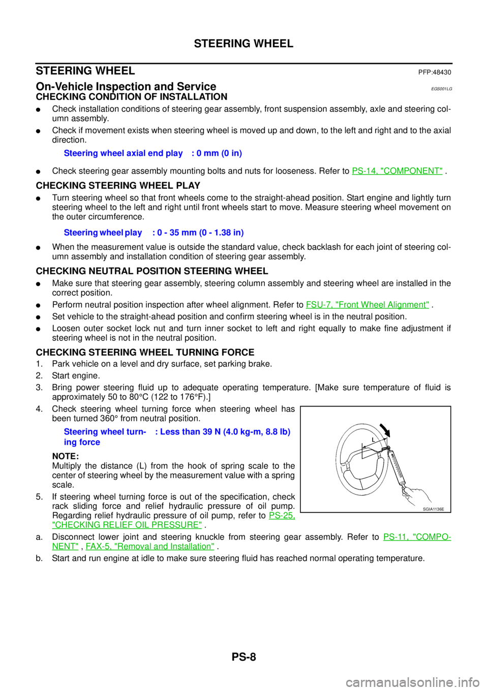
4. Check steering wheel turning force when steering wheel has
been turned 360°from neutral position.
NOTE:
Multiply the distance (L) from the hook of spring scale to the
center of steering wheel by the measurement value with a spring
scale.
5. If steering wheel turning force is out of the specification, check
rack sliding force and relief hydraulic pressure of oil pump.
Regarding relief hydraulic pressure of oil pump, refer toPS-25,
"CHECKING RELIEF OIL PRESSURE".
a. Disconnect lower joint and steering knuckle from steering gear assembly. Refer toPS-11, "
COMPO-
NENT",FAX-5, "Removal and Installation".
b. Start and run engine at idle to make sure steering fluid has reached normal operating temperature.Steering wheel axial end play : 0 mm (0 in)
Steering wheel play : 0 - 35 mm (0 - 1.38 in)
Steering wheel turn-
ing force: Less than 39 N (4.0 kg-m, 8.8 lb)
SGIA1136E