engine oil NISSAN NOTE 2016 Service Repair Manual
[x] Cancel search | Manufacturer: NISSAN, Model Year: 2016, Model line: NOTE, Model: NISSAN NOTE 2016Pages: 3641, PDF Size: 28.72 MB
Page 3497 of 3641
![NISSAN NOTE 2016 Service Repair Manual TM-256
< REMOVAL AND INSTALLATION >[CVT: RE0F11A]
CVT OIL WARMER
CVT OIL WARMER
Exploded ViewINFOID:0000000012431217
Removal and InstallationINFOID:0000000012431218
REMOVAL
WARNING:
Never remove the r](/img/5/57363/w960_57363-3496.png "NISSAN NOTE 2016 Service Repair Manual TM-256
< REMOVAL AND INSTALLATION >[CVT: RE0F11A]
CVT OIL WARMER
CVT OIL WARMER
Exploded ViewINFOID:0000000012431217
Removal and InstallationINFOID:0000000012431218
REMOVAL
WARNING:
Never remove the r")
TM-256
< REMOVAL AND INSTALLATION >[CVT: RE0F11A]
CVT OIL WARMER
CVT OIL WARMER
Exploded ViewINFOID:0000000012431217
Removal and InstallationINFOID:0000000012431218
REMOVAL
WARNING:
Never remove the radiator cap when the engine is hot. Serious burns coul
d occur from high pressure
engine coolant escaping from the radiator. Wrap a thick cloth ar ound the cap. Slowly turn it a quarter
turn to allow built-up pressure to escape. Carefully remove the cap by turning it all the way.
CAUTION:
Perform these steps after the coolant temperature has cooled sufficiently.
1. Pull out water hose from CVT oil warmer. Refer to TM-251, "
Removal and Installation".
2. Pull out fluid cooler hose from CVT oil warmer. Refer to TM-254, "
Removal and Installation".
3. Remove CVT oil warmer.
4. Remove O-ring from CVT oil warmer.
INSTALLATION
Note the followings and install in the reverse order of removal.
CAUTION:
• Never reuse O-ring.
• Apply CVT fluid to O-ring.
InspectionINFOID:0000000012431219
INSPECTION AFTER INSTALLATION
Start the engine and check visually that ther e is no leakage of CVT fluid and engine coolant.
ADJUSTMENT AFTER INSTALLATION
Adjust CVT fluid level. Refer to TM-229, "Adjustment".
1. Transaxle assembly 2. CVT oil warmer 3. O-ring
: Always replace after every disassembly.
: N·m (kg-m, in-lb)
: Apply CVT fluid
JSDIA5447GB
Revision: August 2015 2016 Versa Note
cardiagn.com
Page 3503 of 3641
![NISSAN NOTE 2016 Service Repair Manual TM-262
< UNIT REMOVAL AND INSTALLATION >[CVT: RE0F11A]
TRANSMISSION ASSEMBLY
INSPECTION AFTER INSTALLATION
Check the following items:
• For CVT position, refer to
TM-232, "
Inspection".
• Before](/img/5/57363/w960_57363-3502.png "NISSAN NOTE 2016 Service Repair Manual TM-262
< UNIT REMOVAL AND INSTALLATION >[CVT: RE0F11A]
TRANSMISSION ASSEMBLY
INSPECTION AFTER INSTALLATION
Check the following items:
• For CVT position, refer to
TM-232, \"
Inspection\".
• Before")
TM-262
< UNIT REMOVAL AND INSTALLATION >[CVT: RE0F11A]
TRANSMISSION ASSEMBLY
INSPECTION AFTER INSTALLATION
Check the following items:
• For CVT position, refer to
TM-232, "
Inspection".
• Before starting engine, check oil/fluid levels incl uding engine coolant and engine oil. If less than required
quantity, fill to the specified level. Refer to MA-11, "
Fluids and Lubricants".
• Use procedure below to check for fuel leakage.
• Turn ignition switch ON (with engine stopped). With fuel pressure applied to fuel piping, check for fuel leak-
age at connection points.
• Start engine. With engine speed increased, che ck again for fuel leakage at connection points.
• Run engine to check for unusual noise and vibration. NOTE:
If hydraulic pressure inside timing chain tensioner drops after removal and installation, slack in the guide
may generate a pounding noise during and just after engine start. However, this is normal. Noise will stop
after hydraulic pressure rises.
• Warm up engine thoroughly to make sure there is no leakage of fuel, exhaust gas, or any oils/fluids including engine oil and engine coolant.
• Bleed air from passages in lines and hoses, such as in cooling system.
• After cooling down engine, again check oil/fluid levels including engine oil and engine coolant. Refill to spec- ified level, if necessary.
• Summary of the inspection items:
*Power steering fluid, brake fluid, etc.
ADJUSTMENT AFTER INSTALLATION
• Adjust the CVT fluid level. TM-229, "Adjustment".
• Perform "ADDITIONAL SERVICE WHEN REPL ACING TRANSAXLE ASSEMBLY". Refer to TM-127,
"Description".
ItemBefore starting engine Engine runningAfter engine stopped
Engine coolant LevelLeakage Level
Engine oil LevelLeakage Level
Transmission/
transaxle fluid A/T and CVT Models
LeakageLevel/Leakage Leakage
M/T Models Level/Leakage LeakageLevel/Leakage
Other oils and fluids* LevelLeakage Level
Fuel LeakageLeakageLeakage
Exhaust gas —Leakage —
Revision: August 2015 2016 Versa Note
cardiagn.com
Page 3508 of 3641

VTL-2
< PRECAUTION >
PRECAUTIONS
PRECAUTION
PRECAUTIONS
Precaution for Supplemental Restraint System (SRS) "AIR BAG" and "SEAT BELT
PRE-TENSIONER"
INFOID:0000000012430544
The Supplemental Restraint System such as “A IR BAG” and “SEAT BELT PRE-TENSIONER”, used along
with a front seat belt, helps to reduce the risk or severity of injury to the driver and front passenger for certain
types of collision. Information necessary to service the system safely is included in the SR and SB section of
this Service Manual.
WARNING:
• To avoid rendering the SRS inopera tive, which could increase the risk of personal injury or death in
the event of a collision which would result in air bag inflation, all maintenance must be performed by
an authorized NISSAN/INFINITI dealer.
• Improper maintenance, including in correct removal and installation of the SRS, can lead to personal
injury caused by unintent ional activation of the system. For re moval of Spiral Cable and Air Bag
Module, see the SR section.
• Do not use electrical test equipmen t on any circuit related to the SRS unless instructed to in this
Service Manual. SRS wiring harn esses can be identified by yellow and/or orange harnesses or har-
ness connectors.
PRECAUTIONS WHEN USING POWER TOOLS (AIR OR ELECTRIC) AND HAMMERS
WARNING:
• When working near the Airbag Diagnosis Sensor Unit or other Airbag System sensors with the Igni-
tion ON or engine running, DO NOT use air or electri c power tools or strike near the sensor(s) with a
hammer. Heavy vibration could activate the sensor( s) and deploy the air bag(s), possibly causing
serious injury.
• When using air or electric power tools or hammers , always switch the Ignition OFF, disconnect the
battery and wait at least three minutes before performing any service.
Precaution for WorkINFOID:0000000012430545
• When removing or disassembling each component, be careful not to damage or deform it. If a component may be subject to interference, be sure to protect it with a shop cloth.
• When removing (disengaging) components with a screwdriver or similar tool, be sure to wrap the component with a shop cloth or vinyl tape to protect it.
• Protect the removed parts with a shop cloth and prevent them from being dropped.
• Replace a deformed or damaged clip.
• If a part is specified as a non-reusable part, always replace it with a new one.
• Be sure to tighten bolts and nuts securely to the specified torque.
• After installation is complete, be sure to check that each part works properly.
• Follow the steps below to clean components:
- Water soluble dirt:
• Dip a soft cloth into lukewarm water, wring the water out of the cloth and wipe the dirty area.
• Then rub with a soft, dry cloth.
- Oily dirt:
• Dip a soft cloth into lukewarm water with mild detergent (concentration: within 2 to 3%) and wipe the dirty area.
• Then dip a cloth into fresh water, wring the water out of the cloth and wipe the detergent off.
• Then rub with a soft, dry cloth.
- Do not use organic solvent such as thinner, benzene, alcohol or gasoline.
- For genuine leather seats, use a genuine leather seat cleaner.
Revision: August 2015 2016 Versa Note
cardiagn.com
Page 3530 of 3641
![NISSAN NOTE 2016 Service Repair Manual WCS
DIAGNOSIS SYSTEM (COMBINATION METER)WCS-15
< SYSTEM DESCRIPTION >
C
DE
F
G H
I
J
K L
M B A
O P
NOTE:
Some items are not available according to vehicle specification.
WORK SUPPORT
SLIP IND
[ON/OFF]](/img/5/57363/w960_57363-3529.png "NISSAN NOTE 2016 Service Repair Manual WCS
DIAGNOSIS SYSTEM (COMBINATION METER)WCS-15
< SYSTEM DESCRIPTION >
C
DE
F
G H
I
J
K L
M B A
O P
NOTE:
Some items are not available according to vehicle specification.
WORK SUPPORT
SLIP IND
[ON/OFF]")
WCS
DIAGNOSIS SYSTEM (COMBINATION METER)WCS-15
< SYSTEM DESCRIPTION >
C
DE
F
G H
I
J
K L
M B A
O P
NOTE:
Some items are not available according to vehicle specification.
WORK SUPPORT
SLIP IND
[ON/OFF] Displays [ON/OFF] condition of SLIP indicator lamp.
BRAKE W/L
[ON/OFF] Displays [ON/OFF] condition of brake warning indicator.
DOOR W/L
[ON/OFF] Displays [ON/OFF] condition of door warning indicator.
HI-BEAM IND
[ON/OFF] Displays [ON/OFF] condition of high beam indicator.
TURN IND
[ON/OFF] Displays [ON/OFF] condition of turn indicator.
LIGHT IND
[ON/OFF] Displays [ON/OFF] condition of light indicator.
OIL W/L
[ON/OFF] Displays [ON/OFF] condition of engine oil pressure warning indicator.
MIL
[ON/OFF] Displays [ON/OFF] condition of malfunction indicator.
CRUISE IND
[Off] Displays [ON/OFF]
condition of CRUISE indicator.
O/D OFF IND
[ON/OFF] Displays [ON/OFF] condition of O/D OFF indicator.
FUEL W/L
[ON/OFF] Displays [ON/OFF] condition of low-fuel warning indicator.
AIR PRES W/L
[ON/OFF] Displays [ON/OFF] condition of tire pressure warning lamp.
EPS W/L
[ON/OFF] Displays [ON/OFF] condition of EPS indicator.
CHG SIG
[On/Off] Displays [ON/OFF] condition of charge warning indicator.
PASS BUCKLE
SW
[ON/OFF] Status of seat belt buckle switch RH.
FUEL CAP W/L
[Off] Displays [ON/OFF] condition of loose fuel cap warning message.
PKB SW
[ON/OFF] Status of parking brake switch.
BUCKLE SW
[ON/OFF] Status of seat belt buckle switch LH.
BRAKE OIL SW
[ON/OFF] Status of brake fluid level switch.
DISTANCE
[M] or [Mi] Displays distance to empty.
FUEL LOW SIG
[ON/OFF] Displays [ON/OFF] condition
of low-fuel warning signal.
BUZZER
[ON/OFF] X Displays [ON/OFF] condition of buzzer.
TPMS PRESS L
[ON/OFF] Displays [ON/OFF] condition of check tire pressure warning message.
Display item [Unit]
MAIN
SIGNALS Description
Revision: August 2015
2016 Versa Note
cardiagn.com
Page 3534 of 3641
![NISSAN NOTE 2016 Service Repair Manual WCS
DIAGNOSIS SYSTEM (COMBINATION METER)WCS-19
< SYSTEM DESCRIPTION >
C
DE
F
G H
I
J
K L
M B A
O P
X: Applicable
Display item [Unit] MAIN
SIGNALS Description
SPEED METER
[mph] or [km/h] X Displays the](/img/5/57363/w960_57363-3533.png "NISSAN NOTE 2016 Service Repair Manual WCS
DIAGNOSIS SYSTEM (COMBINATION METER)WCS-19
< SYSTEM DESCRIPTION >
C
DE
F
G H
I
J
K L
M B A
O P
X: Applicable
Display item [Unit] MAIN
SIGNALS Description
SPEED METER
[mph] or [km/h] X Displays the")
WCS
DIAGNOSIS SYSTEM (COMBINATION METER)WCS-19
< SYSTEM DESCRIPTION >
C
DE
F
G H
I
J
K L
M B A
O P
X: Applicable
Display item [Unit] MAIN
SIGNALS Description
SPEED METER
[mph] or [km/h] X Displays the value of vehicle speed signal.
SPEED OUTPUT
[mph] or [km/h] X
Displays the value of vehicle speed signal, which is transmitted to each unit with
CAN communication.
ODO OUTPUT
[mph] or [km/h] Displays odometer signal value transmitted to other units via CAN communica-
tion.
TACHO METER
[rpm] X Displays the value of engine speed signal, which is input from ECM.
FUEL METER
[L] X Displays the fuel level.
W TEMP METER
[ ° C] or [ °F] X Displays the value of engine coolant temperature signal, which is input from ECM.
ABS W/L
[On/Off] Displays [ON/OFF] condition of ABS warning indicator
VDC/TCS IND
[ON/OFF] Displays [ON/OFF] condition of VDC OFF indicator lamp.
SLIP IND
[ON/OFF] Displays [ON/OFF] condition of SLIP indicator lamp.
BRAKE W/L
[On/Off] Displays [ON/OFF] condition of brake warning indicator.
DOOR W/L
[On/Off] Displays [ON/OFF] condition of door warning indicator.
HI-BEAM IND
[On/Off] Displays [ON/OFF] condition of high beam indicator.
TURN IND
[On/Off] Displays [ON/OFF] condition of turn indicator.
LIGHT IND
[On/Off] Displays [ON/OFF] condition of light indicator.
OIL W/L
[On/Off] Displays [ON/OFF] condition of engine oil pressure warning indicator.
MIL
[On/Off] Displays [ON/OFF] condition of malfunction indicator.
CRUISE IND
[Off] Displays [ON/OFF] cond
ition of CRUISE indicator.
O/D OFF IND
[On/Off] Displays [ON/OFF] condition of O/D OFF indicator.
FUEL W/L
[On/Off] Displays [ON/OFF] condition of low-fuel warning indicator.
PASS BUCKLE SW
[On/Off] Status of seat belt buckle switch RH.
AIR PRES W/L
[ON/OFF] Displays [ON/OFF] condition of tire pressure warning lamp.
KEY G/Y W/L
[ON/OFF] Displays [ON/OFF] condition of key warning lamp.
EPS W/L
[On/Off] Displays [ON/OFF] condition of EPS indicator.
FUEL CAP W/L
[Off] Displays [ON/OFF] condition of loose fuel cap warning message.
PKB SW
[On/Off] Status of parking brake switch.
Revision: August 2015
2016 Versa Note
cardiagn.com
Page 3535 of 3641

WCS-20
< SYSTEM DESCRIPTION >
DIAGNOSIS SYSTEM (COMBINATION METER)
NOTE:
Some items are not available according to vehicle specification.
WORK SUPPORT
WARNING HISTORY
W/L ON HISTORY
• Stores histories when warning/indicator lamp is turned on.
• “W/L ON HISTORY” indicates the “TIME” when the warning/ indicator lamp is turned on.
• The “TIME” above is:
- 0: The condition that the warning/indicator lamp has been turned on 1 or more times after starting the engine and waiting for 30 seconds.
- 1 - 39: The number of times the engine was restarted after the 0 condition.
- NO W/L ON HISTORY: Stores NO (0) turning on history of warning/indicator lamp.
NOTE:
• W/L ON HISTORY is not stored for approximately 30 seconds after the engine starts.
• Brake warning lamp does not store any history when the parking brake is applied or the brake fluid level gets low.
BUCKLE SW
[On/Off] Status of seat belt buckle switch (LH).
BRAKE OIL SW
[On/Off] Status of brake fluid level switch.
CHG SIG
[On/Off] Displays [ON/OFF] condition of charge warning indicator.
DISTANCE
[km] or [Mi] Displays distance to empty.
OUTSIDE TEMP
[ ° F] or [ °C] Displays the ambient temperature, which is input from ambient sensor.
FUEL LOW SIG
[ON/OFF] Displays [ON/OFF] condition
of low-fuel warning signal.
BUZZER
[On/Off] X Displays [ON/OFF] condition of buzzer.
FR FOG IND
[On/Off] Displays [ON/OFF] condition of front fog lamp indicator.
TPMS PRESS L
[On/Off] Displays [ON/OFF] condition of check tire pressure warning message.
Display item [Unit]
MAIN
SIGNALS Description
Work support item
Description
Outside air temperature diagnosis A possible malfunction can be narrowed down by following the displayed instructions.
Fuel meter diagnosis(Analog pointer)
Warning lamp diagnosis
Display item Description
W/L ON HISTORY Lighting history of warning lamp and indicator lamp can be checked.
Revision: August 2015 2016 Versa Note
cardiagn.com
Page 3568 of 3641
PRECAUTIONSWW-3
< PRECAUTION >
C
DE
F
G H
I
J
K
M A
B
WW
N
O P
PRECAUTION
PRECAUTIONS
Precaution for Supplemental Restraint System (SRS) "AIR BAG" and "SEAT BELT
PRE-TENSIONER"
INFOID:0000000012433192
The Supplemental Restraint System such as “AIR BAG” and “SEAT BELT PRE-TENSIONER”, used along
with a front seat belt, helps to reduce the risk or severi ty of injury to the driver and front passenger for certain
types of collision. Information necessary to service the system safely is included in the SR and SB section of
this Service Manual.
WARNING:
• To avoid rendering the SRS inoper ative, which could increase the risk of personal injury or death in
the event of a collision which would result in air bag inflation, all maintenance must be performed by
an authorized NISSAN/INFINITI dealer.
• Improper maintenance, including in correct removal and installation of the SRS, can lead to personal
injury caused by unintentional act ivation of the system. For removal of Spiral Cable and Air Bag
Module, see the SR section.
• Do not use electrical test equipm ent on any circuit related to the SRS unless instructed to in this
Service Manual. SRS wiring harnesses can be identi fied by yellow and/or orange harnesses or har-
ness connectors.
PRECAUTIONS WHEN USING POWER TOOLS (AIR OR ELECTRIC) AND HAMMERS
WARNING:
• When working near the Airbag Diagnosis Sensor Un it or other Airbag System sensors with the Igni-
tion ON or engine running, DO NOT use air or el ectric power tools or strike near the sensor(s) with a
hammer. Heavy vibration could activate the sensor( s) and deploy the air bag(s), possibly causing
serious injury.
• When using air or electric power tools or hammers, always switch the Ignition OFF, disconnect the
battery and wait at least three mi nutes before performing any service.
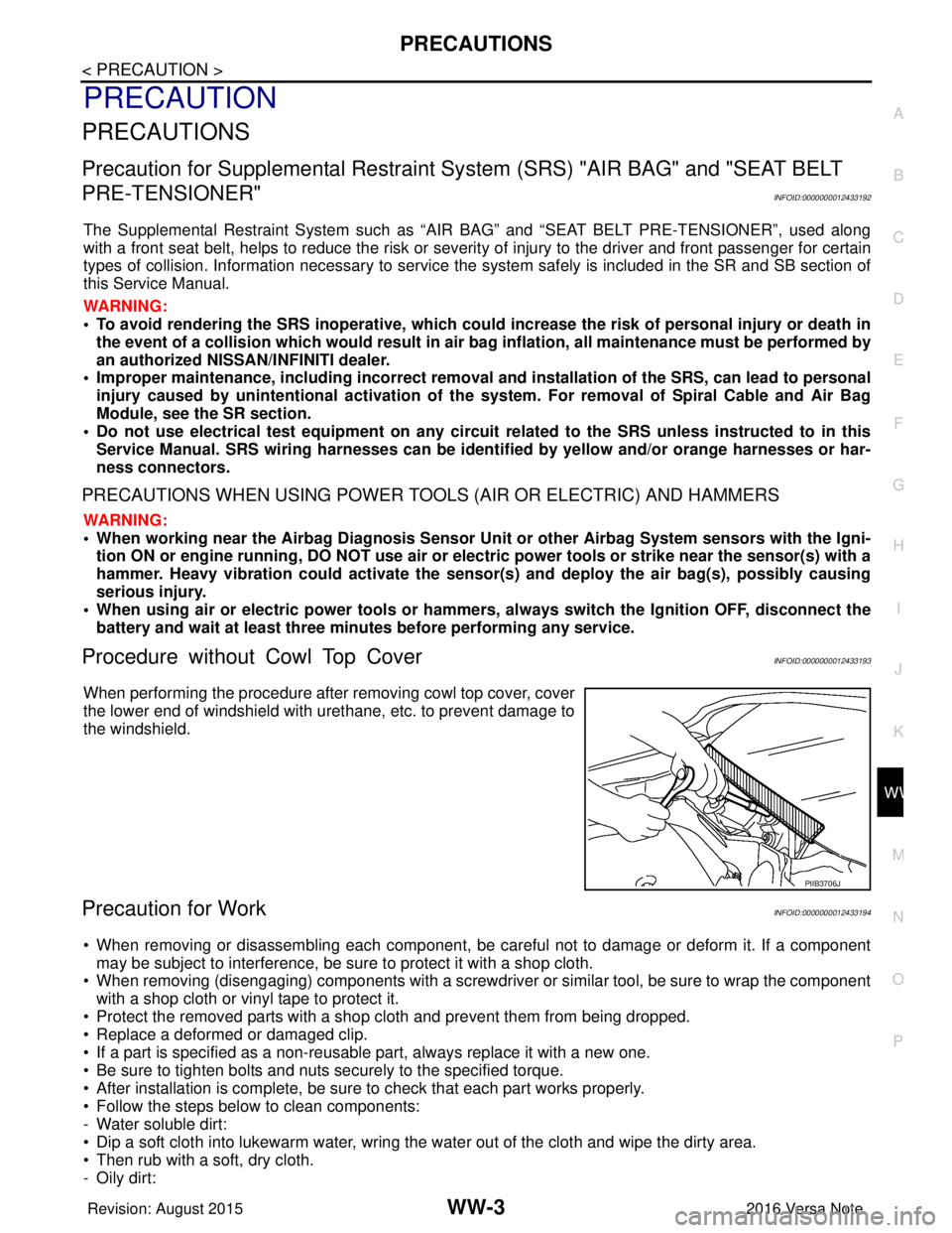
Procedure without Cowl Top CoverINFOID:0000000012433193
When performing the procedure after removing cowl top cover, cover
the lower end of windshield with urethane, etc. to prevent damage to
the windshield.
Precaution for WorkINFOID:0000000012433194
• When removing or disassembling each component, be ca reful not to damage or deform it. If a component
may be subject to interference, be sure to protect it with a shop cloth.
• When removing (disengaging) components with a screwdriver or similar tool, be sure to wrap the component with a shop cloth or vinyl tape to protect it.
• Protect the removed parts with a shop cloth and prevent them from being dropped.
• Replace a deformed or damaged clip.
• If a part is specified as a non-reusabl e part, always replace it with a new one.
• Be sure to tighten bolts and nuts securely to the specified torque.
• After installation is complete, be sure to check that each part works properly.
• Follow the steps below to clean components:
- Water soluble dirt:
• Dip a soft cloth into lukewarm water, wring the water out of the cloth and wipe the dirty area.
• Then rub with a soft, dry cloth.
-Oily dirt:
PIIB3706J
Revision: August 2015 2016 Versa Note
cardiagn.com