NISSAN NOTE 2016 Service Repair Manual
Manufacturer: NISSAN, Model Year: 2016, Model line: NOTE, Model: NISSAN NOTE 2016Pages: 3641, PDF Size: 28.72 MB
Page 3201 of 3641

DIAGNOSIS AND REPAIR WORKFLOWSTC-17
< BASIC INSPECTION >
C
DE
F
H I
J
K L
M A
B
STC
N
O P
Other conditions
Memo Interview sheet
Customer
name MR/MSRegistration
number
Initial year
registration
Vehicle type VIN
Storage date EngineMileagekm (Mile)
Revision: August 2015 2016 Versa Note
cardiagn.com
Page 3202 of 3641
STC-18
< DTC/CIRCUIT DIAGNOSIS >
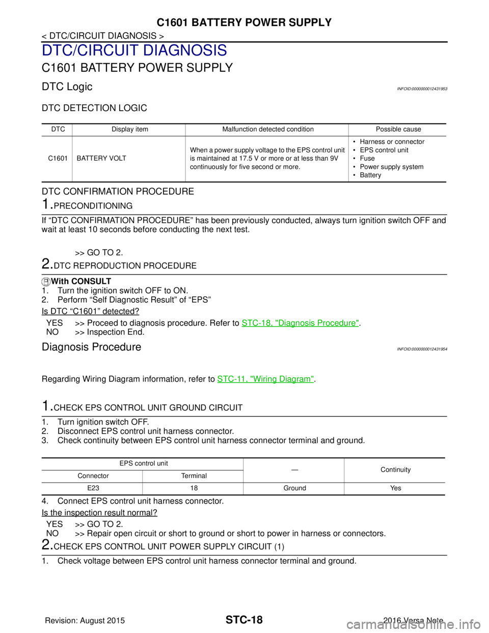
C1601 BATTERY POWER SUPPLY
DTC/CIRCUIT DIAGNOSIS
C1601 BATTERY POWER SUPPLY
DTC LogicINFOID:0000000012431953
DTC DETECTION LOGIC
DTC CONFIRMATION PROCEDURE
1.PRECONDITIONING
If “DTC CONFIRMATION PROCEDURE” has been previously conducted, always turn ignition switch OFF and
wait at least 10 seconds before conducting the next test.
>> GO TO 2.
2.DTC REPRODUCTION PROCEDURE
With CONSULT
1. Turn the ignition switch OFF to ON.
2. Perform “Self Diagnostic Result” of “EPS”
Is DTC
“C1601” detected?
YES >> Proceed to diagnosis procedure. Refer to STC-18, "Diagnosis Procedure".
NO >> Inspection End.
Diagnosis ProcedureINFOID:0000000012431954
Regarding Wiring Diagram information, refer to STC-11, "Wiring Diagram".
1.CHECK EPS CONTROL UNIT GROUND CIRCUIT
1. Turn ignition switch OFF.
2. Disconnect EPS control unit harness connector.
3. Check continuity between EPS contro l unit harness connector terminal and ground.
4. Connect EPS control unit harness connector.
Is the inspection result normal?
YES >> GO TO 2.
NO >> Repair open circuit or short to ground or short to power in harness or connectors.
2.CHECK EPS CONTROL UNIT PO WER SUPPLY CIRCUIT (1)
1. Check voltage between EPS control unit harness connector terminal and ground.
DTC Display item Malfunction detected condition Possible cause
C1601 BATTERY VOLT When a power supply voltage to the EPS control unit
is maintained at 17.5 V or more or at less than 9V
continuously for five second or more. • Harness or connector
• EPS control unit
•Fuse
• Power supply system
•Battery
EPS control unit
—Con tin uit y
Connector Terminal
E23 18Ground Yes
Revision: August 2015 2016 Versa Note
cardiagn.com
Page 3203 of 3641
C1601 BATTERY POWER SUPPLYSTC-19
< DTC/CIRCUIT DIAGNOSIS >
C
DE
F
H I
J
K L
M A
B
STC
N
O P
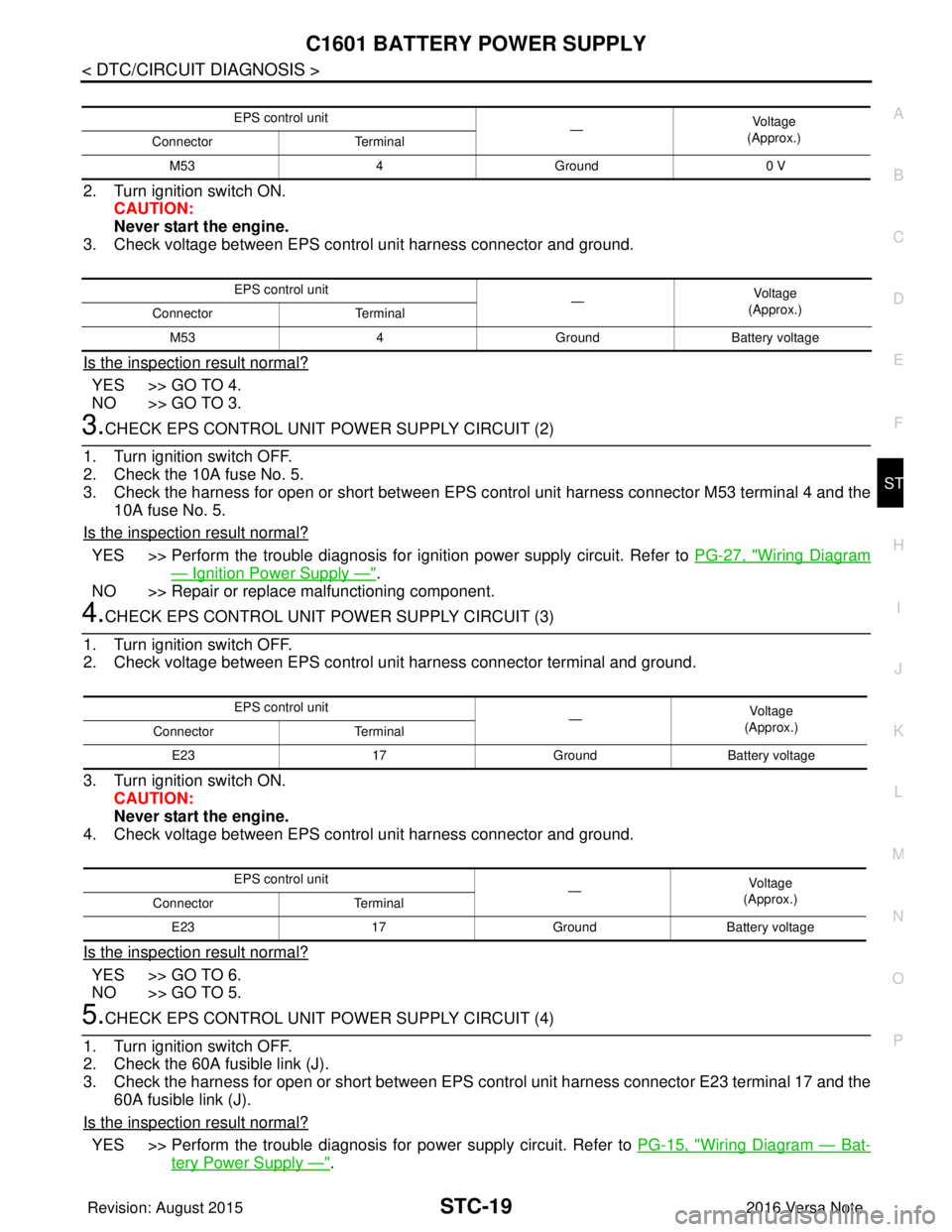
2. Turn ignition switch ON. CAUTION:
Never start the engine.
3. Check voltage between EPS control unit harness connector and ground.
Is the inspection result normal?
YES >> GO TO 4.
NO >> GO TO 3.
3.CHECK EPS CONTROL UNIT POWER SUPPLY CIRCUIT (2)
1. Turn ignition switch OFF.
2. Check the 10A fuse No. 5.
3. Check the harness for open or short between EPS c ontrol unit harness connector M53 terminal 4 and the
10A fuse No. 5.
Is the inspection result normal?
YES >> Perform the trouble diagnosis for i gnition power supply circuit. Refer to PG-27, "Wiring Diagram
— Ignition Power Supply —".
NO >> Repair or replace malfunctioning component.
4.CHECK EPS CONTROL UNIT POWER SUPPLY CIRCUIT (3)
1. Turn ignition switch OFF.
2. Check voltage between EPS control unit harness connector terminal and ground.
3. Turn ignition switch ON. CAUTION:
Never start the engine.
4. Check voltage between EPS control unit harness connector and ground.
Is the inspection result normal?
YES >> GO TO 6.
NO >> GO TO 5.
5.CHECK EPS CONTROL UNIT POWER SUPPLY CIRCUIT (4)
1. Turn ignition switch OFF.
2. Check the 60A fusible link (J).
3. Check the harness for open or short between EPS c ontrol unit harness connector E23 terminal 17 and the
60A fusible link (J).
Is the inspection result normal?
YES >> Perform the trouble diagnosis fo r power supply circuit. Refer to PG-15, "Wiring Diagram — Bat-
tery Power Supply —".
EPS control unit
—Vol tag e
(Approx.)
Connector Terminal
M53 4Ground 0 V
EPS control unit
—Voltage
(Approx.)
Connector Terminal
M53 4GroundBattery voltage
EPS control unit
—Vo l ta g e
(Approx.)
Connector Terminal
E23 17GroundBattery voltage
EPS control unit —Vol tag e
(Approx.)
Connector Terminal
E23 17GroundBattery voltage
Revision: August 2015 2016 Versa Note
cardiagn.com
Page 3204 of 3641

STC-20
< DTC/CIRCUIT DIAGNOSIS >
C1601 BATTERY POWER SUPPLY
NO >> Repair or replace malfunctioning component.
6.CHECK CONNECTOR
1. Turn ignition switch OFF.
2. Disconnect torque sensor harness connector.
3. Check terminal for deformation, disconnection, looseness, and so on. If any malfunction is found, repair or replace terminal.
Is the inspection result normal?
YES >> Replace EPS control unit. Refer to STC-37, "Removal and Installation".
NO >> Repair or replace malfunctioning component.
Revision: August 2015 2016 Versa Note
cardiagn.com
Page 3205 of 3641
C1604 TORQUE SENSORSTC-21
< DTC/CIRCUIT DIAGNOSIS >
C
DE
F
H I
J
K L
M A
B
STC
N
O P
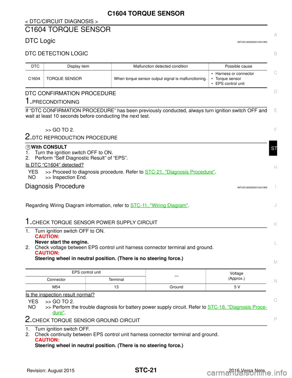
C1604 TORQUE SENSOR
DTC LogicINFOID:0000000012431955
DTC DETECTION LOGIC
DTC CONFIRMATION PROCEDURE
1.PRECONDITIONING
If “DTC CONFIRMATION PROCEDURE” has been previously conducted, always turn ignition switch OFF and
wait at least 10 seconds before conducting the next test.
>> GO TO 2.
2.DTC REPRODUCTION PROCEDURE
With CONSULT
1. Turn the ignition switch OFF to ON.
2. Perform “Self Diagnostic Result” of “EPS”.
Is DTC
“C1604” detected?
YES >> Proceed to diagnosis procedure. Refer to STC-21, "Diagnosis Procedure".
NO >> Inspection End.
Diagnosis ProcedureINFOID:0000000012431956
Regarding Wiring Diagram information, refer to STC-11, "Wiring Diagram".
1.CHECK TORQUE SENSOR POWER SUPPLY CIRCUIT
1. Turn ignition switch OFF to ON. CAUTION:
Never start the engine.
2. Check voltage between EPS control unit harness connector terminal and ground.
CAUTION:
Steering wheel in neutral position . (There is no steering force.)
Is the inspection result normal?
YES >> GO TO 2.
NO >> Perform the trouble diagnosis for battery power supply circuit. Refer to STC-18, "
Diagnosis Proce-
dure".
2.CHECK TORQUE SENSOR GROUND CIRCUIT
1. Turn ignition switch OFF.
2. Check continuity between EPS control unit harness connector terminal and ground. CAUTION:
Steering wheel in neutral position . (There is no steering force.)
DTCDisplay item Malfunction detected condition Possible cause
C1604 TORQUE SENSOR When torque sensor output signal is malfunctioning. • Harness or connector
• Torque sensor
• EPS control unit
EPS control unit
—Vo l ta g e
(Approx.)
Connector Terminal
M54 13Ground 5 V
Revision: August 2015 2016 Versa Note
cardiagn.com
Page 3206 of 3641

STC-22
< DTC/CIRCUIT DIAGNOSIS >
C1604 TORQUE SENSOR
Is the inspection result normal?
YES >> GO TO 3.
NO >> Repair open circuit or short to ground or short to power in harness or connectors.
3.CHECK TORQUE SENSOR SIGNAL
1. Turn ignition switch OFF to ON.
2. Check voltage between EPS control unit harness connector terminal and ground. CAUTION:
Steering wheel in neutral position. (There is no steering force.)
3. Start the engine.
4. Check voltage between EPS control unit harness connector terminal and ground while turning the steer- ing wheel.
Is the inspection result normal?
YES >> GO TO 4.
NO >> Torque sensor is malfunctioning. Repl ace steering column assembly. Refer to ST-9, "
Exploded
View".
4.CHECK CONNECTOR
1. Turn ignition switch OFF.
2. Disconnect EPS control unit harness connector.
3. Check terminal for deformation, disconnection, looseness, and so on. If any malfunction is found, repair or replace terminal.
Is the inspection result normal?
YES >> Replace EPS control unit. Refer to STC-37, "Removal and Installation".
NO >> Repair or replace malfunctioning component.
EPS control unit —Continuity
Connector Terminal
M54 15Ground Yes
EPS control unit
—Vo l ta g e
(Approx.)
Connector Terminal
M54 16
Ground 2.5 V
14
EPS control unit —Voltag e
(Approx.)
Connector Terminal
M54 16
Ground 1.6 V – 3.4 V
(The value is changed according to steering left or right)
14
Revision: August 2015
2016 Versa Note
cardiagn.com
Page 3207 of 3641
C1606 EPS MOTORSTC-23
< DTC/CIRCUIT DIAGNOSIS >
C
DE
F
H I
J
K L
M A
B
STC
N
O P
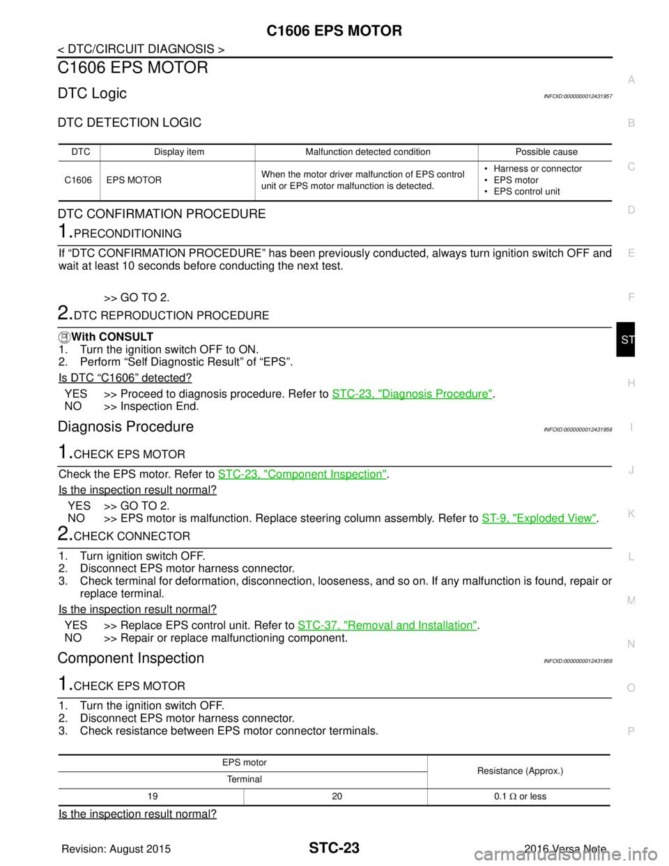
C1606 EPS MOTOR
DTC LogicINFOID:0000000012431957
DTC DETECTION LOGIC
DTC CONFIRMATION PROCEDURE
1.PRECONDITIONING
If “DTC CONFIRMATION PROCEDURE” has been previously conducted, always turn ignition switch OFF and
wait at least 10 seconds before conducting the next test.
>> GO TO 2.
2.DTC REPRODUCTION PROCEDURE
With CONSULT
1. Turn the ignition switch OFF to ON.
2. Perform “Self Diagnostic Result” of “EPS”.
Is DTC
“C1606” detected?
YES >> Proceed to diagnosis procedure. Refer to STC-23, "Diagnosis Procedure".
NO >> Inspection End.
Diagnosis ProcedureINFOID:0000000012431958
1.CHECK EPS MOTOR
Check the EPS motor. Refer to STC-23, "
Component Inspection".
Is the inspection result normal?
YES >> GO TO 2.
NO >> EPS motor is malfunction. Replace steering column assembly. Refer to ST-9, "
Exploded View".
2.CHECK CONNECTOR
1. Turn ignition switch OFF.
2. Disconnect EPS motor harness connector.
3. Check terminal for deformation, disconnection, looseness, and so on. If any malfunction is found, repair or replace terminal.
Is the inspection result normal?
YES >> Replace EPS control unit. Refer to STC-37, "Removal and Installation".
NO >> Repair or replace malfunctioning component.
Component Inspection INFOID:0000000012431959
1.CHECK EPS MOTOR
1. Turn the ignition switch OFF.
2. Disconnect EPS motor harness connector.
3. Check resistance between EPS motor connector terminals.
Is the inspection result normal?
DTC Display item Malfunction detected condition Possible cause
C1606 EPS MOTOR When the motor driver malfunction of EPS control
unit or EPS motor malfunction is detected. • Harness or connector
• EPS motor
• EPS control unit
EPS motor
Resistance (Approx.)
Te r m i n a l
19 200.1 Ω or less
Revision: August 2015 2016 Versa Note
cardiagn.com
Page 3208 of 3641

STC-24
< DTC/CIRCUIT DIAGNOSIS >
C1606 EPS MOTOR
YES >> Inspection End.
NO >> EPS motor is malfunctioning. Replace steering column assembly. Refer to ST-9, "
Removal and
Installation".
Revision: August 2015 2016 Versa Note
cardiagn.com
Page 3209 of 3641
C1607, C1608 EPS CONTROL UNIT
STC-25
< DTC/CIRCUIT DIAGNOSIS >
C
D E
F
H I
J
K L
M A
B
STC
N
O P
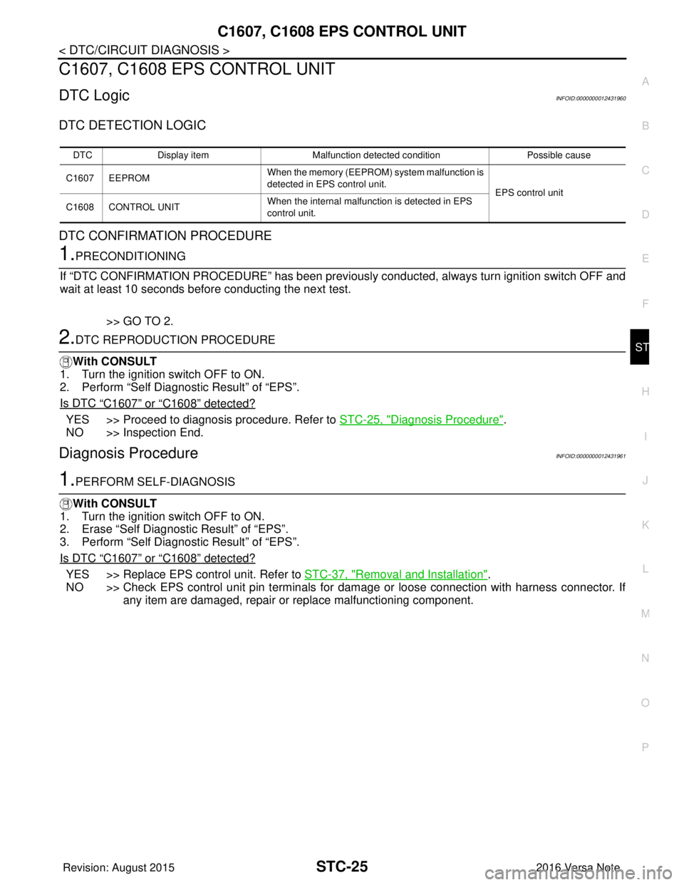
C1607, C1608 EPS CONTROL UNIT
DTC LogicINFOID:0000000012431960
DTC DETECTION LOGIC
DTC CONFIRMATION PROCEDURE
1.PRECONDITIONING
If “DTC CONFIRMATION PROCEDURE” has been previously conducted, always turn ignition switch OFF and
wait at least 10 seconds before conducting the next test.
>> GO TO 2.
2.DTC REPRODUCTION PROCEDURE
With CONSULT
1. Turn the ignition switch OFF to ON.
2. Perform “Self Diagnostic Result” of “EPS”.
Is DTC
“C1607” or “C1608” detected?
YES >> Proceed to diagnosis procedure. Refer to STC-25, "Diagnosis Procedure".
NO >> Inspection End.
Diagnosis ProcedureINFOID:0000000012431961
1.PERFORM SELF-DIAGNOSIS
With CONSULT
1. Turn the ignition switch OFF to ON.
2. Erase “Self Diagnostic Result” of “EPS”.
3. Perform “Self Diagnostic Result” of “EPS”.
Is DTC
“C1607” or “C1608” detected?
YES >> Replace EPS control unit. Refer to STC-37, "Removal and Installation".
NO >> Check EPS control unit pin terminals for damage or loose connection with harness connector. If
any item are damaged, repair or replace malfunctioning component.
DTC Display item Malfunction detected condition Possible cause
C1607 EEPROM When the memory (EEPROM)
system malfunction is
detected in EPS control unit.
EPS control unit
C1608 CONTROL UNIT When the internal malfunction is detected in EPS
control unit.
Revision: August 2015
2016 Versa Note
cardiagn.com
Page 3210 of 3641
STC-26
< DTC/CIRCUIT DIAGNOSIS >
C1609 VEHICLE SPEED SIGNAL
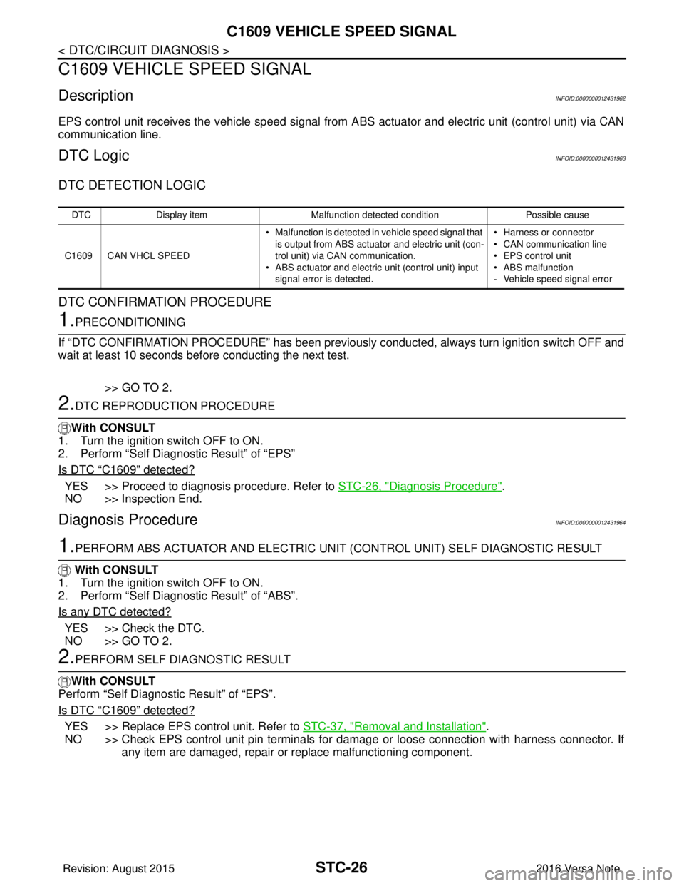
C1609 VEHICLE SPEED SIGNAL
DescriptionINFOID:0000000012431962
EPS control unit receives the vehicle speed signal from ABS actuator and electric unit (control unit) via CAN
communication line.
DTC LogicINFOID:0000000012431963
DTC DETECTION LOGIC
DTC CONFIRMATION PROCEDURE
1.PRECONDITIONING
If “DTC CONFIRMATION PROCEDURE” has been previously conducted, always turn ignition switch OFF and
wait at least 10 seconds before conducting the next test.
>> GO TO 2.
2.DTC REPRODUCTION PROCEDURE
With CONSULT
1. Turn the ignition switch OFF to ON.
2. Perform “Self Diagnostic Result” of “EPS”
Is DTC
“C1609” detected?
YES >> Proceed to diagnosis procedure. Refer to STC-26, "Diagnosis Procedure".
NO >> Inspection End.
Diagnosis ProcedureINFOID:0000000012431964
1.PERFORM ABS ACTUATOR AND ELECTRIC UNIT (CONTROL UNIT) SELF DIAGNOSTIC RESULT
With CONSULT
1. Turn the ignition switch OFF to ON.
2. Perform “Self Diagnostic Result” of “ABS”.
Is any DTC detected?
YES >> Check the DTC.
NO >> GO TO 2.
2.PERFORM SELF DIAGNOSTIC RESULT
With CONSULT
Perform “Self Diagnostic Result” of “EPS”.
Is DTC
“C1609” detected?
YES >> Replace EPS control unit. Refer to STC-37, "Removal and Installation".
NO >> Check EPS control unit pin terminals for damage or loose connection with harness connector. If any item are damaged, repair or replace malfunctioning component.
DTC Display item Malfunction detected condition Possible cause
C1609 CAN VHCL SPEED • Malfunction is detected in vehicle speed signal that
is output from ABS actuator and electric unit (con-
trol unit) via CAN communication.
• ABS actuator and electric unit (control unit) input signal error is detected. • Harness or connector
• CAN communication line
• EPS control unit
• ABS malfunction
- Vehicle speed signal error
Revision: August 2015
2016 Versa Note
cardiagn.com