service reset NISSAN NOTE 2016 Service Repair Manual
[x] Cancel search | Manufacturer: NISSAN, Model Year: 2016, Model line: NOTE, Model: NISSAN NOTE 2016Pages: 3641, PDF Size: 28.72 MB
Page 1182 of 3641
![NISSAN NOTE 2016 Service Repair Manual DIAGNOSIS SYSTEM (ECM)EC-55
< SYSTEM DESCRIPTION > [HR16DE]
C
D
E
F
G H
I
J
K L
M A
EC
NP
O
Calculated load value: (Calculated load value in the freeze frame data) x (1
±0.1) [%]
Engine coolant tempe NISSAN NOTE 2016 Service Repair Manual DIAGNOSIS SYSTEM (ECM)EC-55
< SYSTEM DESCRIPTION > [HR16DE]
C
D
E
F
G H
I
J
K L
M A
EC
NP
O
Calculated load value: (Calculated load value in the freeze frame data) x (1
±0.1) [%]
Engine coolant tempe](/img/5/57363/w960_57363-1181.png)
DIAGNOSIS SYSTEM (ECM)EC-55
< SYSTEM DESCRIPTION > [HR16DE]
C
D
E
F
G H
I
J
K L
M A
EC
NP
O
Calculated load value: (Calculated load value in the freeze frame data) x (1
±0.1) [%]
Engine coolant temperature condition:
• When the freeze frame data shows lower than 70 °C (158° F), engine coolant temperature should be lower
than 70 °C (158 °F).
• When the freeze frame data shows higher than or equal to 70 °C (158° F), engine coolant temperature should
be higher than or equal to 70 °C (158° F).
NOTE:
• When the same malfunction is detected regardless of t he above vehicle conditions, reset the counter of driv-
ing pattern C.
• When the above conditions are satisfied without detecting t he same malfunction, reset the counter of driving
pattern C.
• The 1st trip DTC will be cleared when C counter is counted once without the same malfunction after DTC is stored in ECM.
DRIVING PATTERN D
Driving pattern D means a trip satisfying the following conditions.
• The state of driving at 40 km/h (25 MPH) reaches 300 seconds or more in total.
• Idle speed lasts 30 seconds or more.
• A lapse of 600 seconds or more after engine start.
NOTE:
• When the same malfunction is detected regardless of driv ing conditions, reset the counter of driving pattern
D.
• When the above conditions are satisfied without detecting the same malfunction, reset the counter of driving
pattern D.
DIAGNOSIS DESCRIPTION : System Readiness Test (SRT) CodeINFOID:0000000012431337
System Readiness Test (SRT) code is specified in Service $01 of SAE J1979/ISO 15031-5.
As part of an enhanced emissions test for Inspection & Ma intenance (I/M), certain states require the status of
SRT be used to indicate whether the ECM has comple ted self-diagnosis of major emission systems and com-
ponents. Completion must be verified in order for the emissions inspection to proceed.
If a vehicle is rejected for a State emissions inspection due to one or more SRT items indicating “INCMP”, use
the information in this Service Manual to set the SRT to “CMPLT”.
In most cases the ECM will automatically complete its self-diagnosis cycle during normal usage, and the SRT
status will indicate “CMPLT” for each application system. Once set as “CMPLT”, the SRT status remains
“CMPLT” until the self-diagnosis memory is erased.
Occasionally, certain portions of the self-diagnostic test may not be completed as a result of the customer's
normal driving pattern; the SRT will indicate “INCMP” for these items.
NOTE:
The SRT will also indicate “INCMP” if the self-diagnosis memory is erased for any reason or if the ECM mem-
ory power supply is interrupted for several hours.
If, during the state emissions inspection, the SRT indicates “CMPLT” for all test items, the inspector will con-
tinue with the emissions test. However, if the SRT i ndicates “INCMP” for one or more of the SRT items the
vehicle is returned to the customer untested.
NOTE:
If permanent DTC is stored or MIL illuminates during the state emissions inspection, the vehicle is also
returned to the customer untested even though the SRT indicates “CMPLT” for all test items. Therefore, it is
important to check SRT (“CMPLT”), DTC (No DT Cs) and permanent DTC (No permanent DTC) before the
inspection.
SRT SET TIMING
SRT is set as “CMPLT” after self-diagnosis has been performed one or more times. Completion of SRT is
done regardless of whether the result is OK or NG. T he set timing is different between OK and NG results and
is shown in the table below.
Revision: August 2015 2016 Versa Note
cardiagn.com
Page 1276 of 3641
![NISSAN NOTE 2016 Service Repair Manual HOW TO ERASE PERMANENT DTCEC-149
< BASIC INSPECTION > [HR16DE]
C
D
E
F
G H
I
J
K L
M A
EC
NP
O
4. Turn ignition switch ON.
5. Select Service $0A with GST.
Is any permanent DTC detected?
YES >> GO TO 3 NISSAN NOTE 2016 Service Repair Manual HOW TO ERASE PERMANENT DTCEC-149
< BASIC INSPECTION > [HR16DE]
C
D
E
F
G H
I
J
K L
M A
EC
NP
O
4. Turn ignition switch ON.
5. Select Service $0A with GST.
Is any permanent DTC detected?
YES >> GO TO 3](/img/5/57363/w960_57363-1275.png)
HOW TO ERASE PERMANENT DTCEC-149
< BASIC INSPECTION > [HR16DE]
C
D
E
F
G H
I
J
K L
M A
EC
NP
O
4. Turn ignition switch ON.
5. Select Service $0A with GST.
Is any permanent DTC detected?
YES >> GO TO 3.
NO >> END
3.DRIVE DRIVING PATTERN B
CAUTION:
• Always drive at a safe speed.
• Never erase self-diagnosis results.
• If self-diagnosis results are erased during the trip of driving pattern B or D, the counter of driving
pattern B and D is reset.
With CONSULT
1. Start engine and warm it up to normal operating temperature.
2. Use “PERMANENT DTC WORK SUPPORT” mode with CONS ULT to drive the vehicle according to driv-
ing pattern B. Refer to EC-60, "
CONSULT Function", EC-54, "DIAGNOSIS DESCRIPTION : Driving Pat-
tern".
With GST
1. Start engine and warm it up to normal operating temperature.
2. Drive the vehicle according to driving pattern B. Refer to EC-54, "
DIAGNOSIS DESCRIPTION : Driving
Pattern".
>> GO TO 4.
4.CHECK PERMANENT DTC
With CONSULT
1. Turn ignition switch OFF and wait at least 10 seconds.
2. Turn ignition switch ON.
3. Turn ignition switch OFF and wait at least 10 seconds.
4. Turn ignition switch ON.
5. Select “PERMANENT DTC STATUS” mode with CONSULT.
With GST
1. Turn ignition switch OFF and wait at least 10 seconds.
2. Turn ignition switch ON.
3. Turn ignition switch OFF and wait at least 10 seconds.
4. Turn ignition switch ON.
5. Select Service $0A with GST.
Is any permanent DTC detected?
YES >> GO TO 5.
NO >> END
5.DRIVE DRIVING PATTERN D
CAUTION:
• Always drive at a safe speed.
• Never erase self-diagnosis results.
• If self-diagnosis results are erased during the trip of driving pattern B or D, the counter of driving
pattern B and D is reset.
Drive the vehicle according to driving pattern D. Refer to EC-54, "
DIAGNOSIS DESCRIPTION : Driving Pat-
tern".
>> GO TO 6.
6.CHECK PERMANENT DTC
With CONSULT
1. Turn ignition switch OFF and wait at least 10 seconds.
2. Turn ignition switch ON.
3. Turn ignition switch OFF and wait at least 10 seconds.
4. Turn ignition switch ON.
Revision: August 2015 2016 Versa Note
cardiagn.com
Page 2651 of 3641

PG-64
< BASIC INSPECTION >
INSPECTION AND ADJUSTMENT
INSPECTION AND ADJUSTMENT
ADDITIONAL SERVICE WHEN REMOVING BATTERY NEGATIVE TERMINAL
ADDITIONAL SERVICE WHEN REMOVING BATTERY NEGATIVE TERMINAL : Spe-
cial Repair Requirement
INFOID:0000000012433129
Required Procedure After Battery Disconnection
System ItemReference
Engine Control System Idle Air Volume Learning EC-130
Audio, Visual & Navigation SystemAudio (Radio Preset) Refer to Owner's Manual.
Navigation System
Refer to Owner's Manual.
Revision: August 2015 2016 Versa Note
cardiagn.com
Page 2657 of 3641
PG-70
< REMOVAL AND INSTALLATION >
BATTERY
REMOVAL AND INSTALLATION
BATTERY
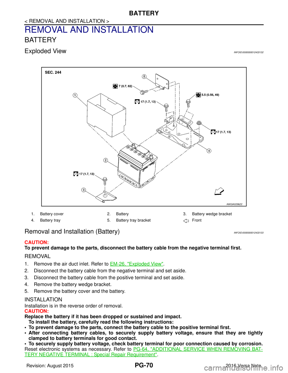
Exploded ViewINFOID:0000000012433132
Removal and Installation (Battery)INFOID:0000000012433133
CAUTION:
To prevent damage to the parts, disconnect the battery cable from the negative terminal first.
REMOVAL
1. Remove the air duct inlet. Refer to EM-26, "Exploded View".
2. Disconnect the battery cable from the negative terminal and set aside.
3. Disconnect the battery cable from the positive terminal and set aside.
4. Remove the battery wedge bracket.
5. Remove the battery cover and the battery.
INSTALLATION
Installation is in the reverse order of removal.
CAUTION:
Replace the battery if it has been dropped or sustained and impact. To install the battery, carefully read the following instructions:
• To prevent damage to the parts, connect the battery cable to the positive terminal first.
• After connecting battery cables, to securely supply battery voltage, ensure that they are tightly
clamped to battery term inals for good contact.
• To securely supply battery voltage, check battery terminal for poor connection caused by corrosion.
Reset electronic systems as necessary. Refer to PG-64, "
ADDITIONAL SERVICE WHEN REMOVING BAT-
TERY NEGATIVE TERMINAL : Special Repair Requirement".
AWGIA0296ZZ
1. Battery cover2. Battery3. Battery wedge bracket
4. Battery tray 5. Battery tray bracket Front
Revision: August 2015 2016 Versa Note
cardiagn.com
Page 2658 of 3641
PG
BATTERYPG-71
< REMOVAL AND INSTALLATION >
C
DE
F
G H
I
J
K L
B A
O P
N
Removal and Installation (Battery Tray)INFOID:0000000012433134
CAUTION:
To prevent damage to the parts, disconnect the battery cable from the negative terminal first.
REMOVAL
1. Remove the battery. Refer to
PG-70, "Removal and Installation (Battery)".
2. Remove the battery tray bracket. Refer to PG-70, "
Exploded View".
3. Remove the IPDM E/R. Refer to PCS-30, "
Removal and Installation".
4. Disconnect the harness from the TCM and remove the TCM bracket. Refer to TM-239, "
Removal and
Installation" (FOR CVT MODEL).
5. Disconnect the harness fr om the battery tray.
6. Remove the nuts and bolts and remove the battery tray. Refer to PG-70, "
Exploded View".
INSTALLATION
Installation is in the reverse order of removal.
CAUTION:
Replace electrical components as necessary, if any have been dropped or sustained and impact.
To install the battery, carefully read the following instructions:
• To prevent damage to the parts, connect the battery cable to the positive terminal first.
• After connecting battery cables, to securely supp ly battery voltage, ensure that they are tightly
clamped to battery terminals for good contact.
• To securely supply battery voltage, check battery terminal for poor connection caused by corrosion.
Reset electronic systems as necessary. Refer to PG-64, "
ADDITIONAL SERVICE WHEN REMOVING BAT-
TERY NEGATIVE TERMINAL : Special Repair Requirement".
Revision: August 2015 2016 Versa Note
cardiagn.com
Page 2659 of 3641
PG-72
< REMOVAL AND INSTALLATION >
BATTERY TERMINAL WITH FUSIBLE LINK
BATTERY TERMINAL WITH FUSIBLE LINK
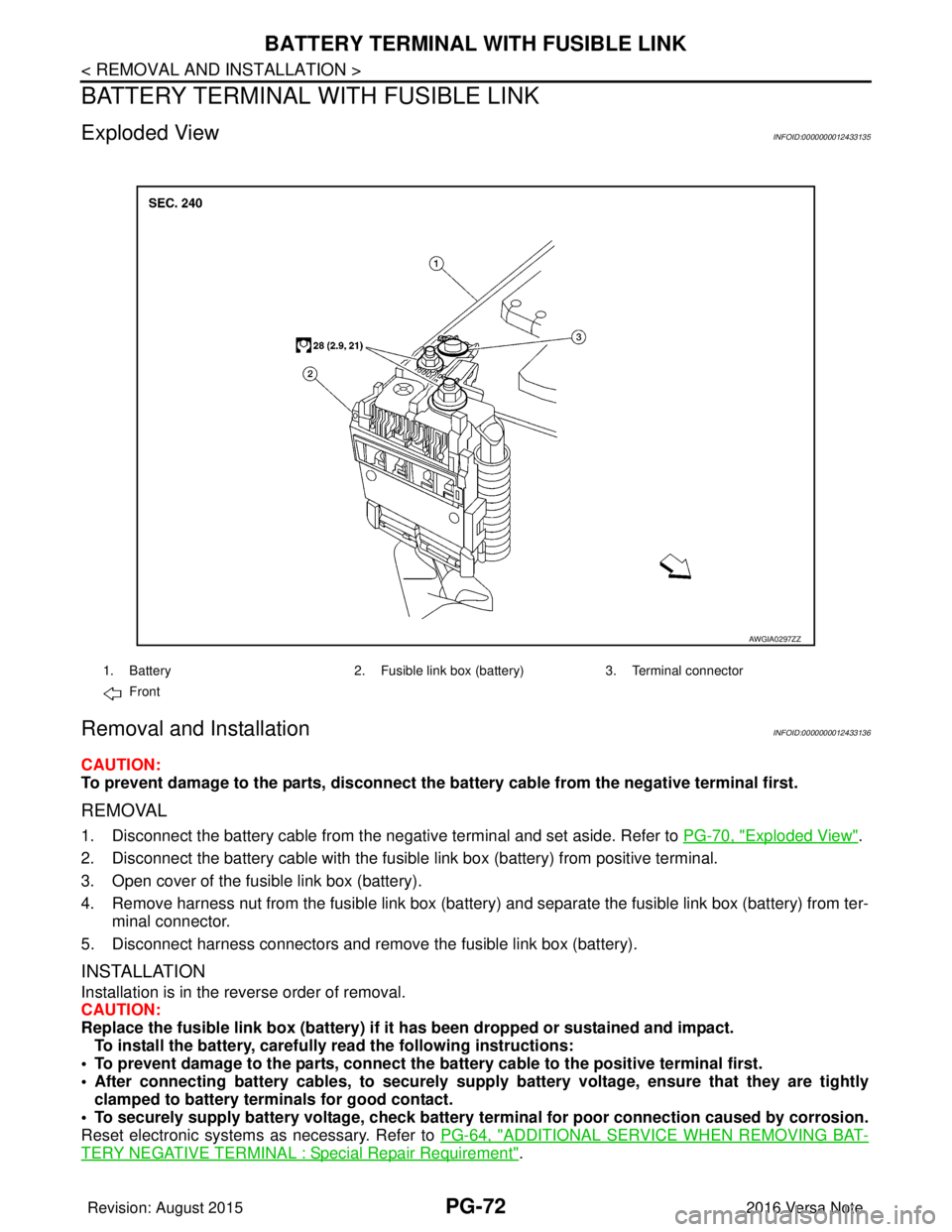
Exploded ViewINFOID:0000000012433135
Removal and InstallationINFOID:0000000012433136
CAUTION:
To prevent damage to the parts, disconnect the battery cable from the negative terminal first.
REMOVAL
1. Disconnect the battery cable from the negative terminal and set aside. Refer to PG-70, "Exploded View".
2. Disconnect the battery cable with the fusibl e link box (battery) from positive terminal.
3. Open cover of the fusible link box (battery).
4. Remove harness nut from the fusible link box (battery ) and separate the fusible link box (battery) from ter-
minal connector.
5. Disconnect harness connectors and remove the fusible link box (battery).
INSTALLATION
Installation is in the reverse order of removal.
CAUTION:
Replace the fusible link box (battery) if it has been dropped or sustained and impact.
To install the battery, carefully read the following instructions:
• To prevent damage to the parts, connect the battery cable to the positive terminal first.
• After connecting battery cables, to securely supply battery voltage, ensure that they are tightly
clamped to battery term inals for good contact.
• To securely supply battery voltage, check battery terminal for poor connection caused by corrosion.
Reset electronic systems as necessary. Refer to PG-64, "
ADDITIONAL SERVICE WHEN REMOVING BAT-
TERY NEGATIVE TERMINAL : Special Repair Requirement".
AWGIA0297ZZ
1. Battery2. Fusible link box (battery) 3. Terminal connector
Front
Revision: August 2015 2016 Versa Note
cardiagn.com
Page 2660 of 3641
PG
BATTERY CURRENT SENSORPG-73
< REMOVAL AND INSTALLATION >
C
DE
F
G H
I
J
K L
B A
O P
N
BATTERY CURRENT SENSOR
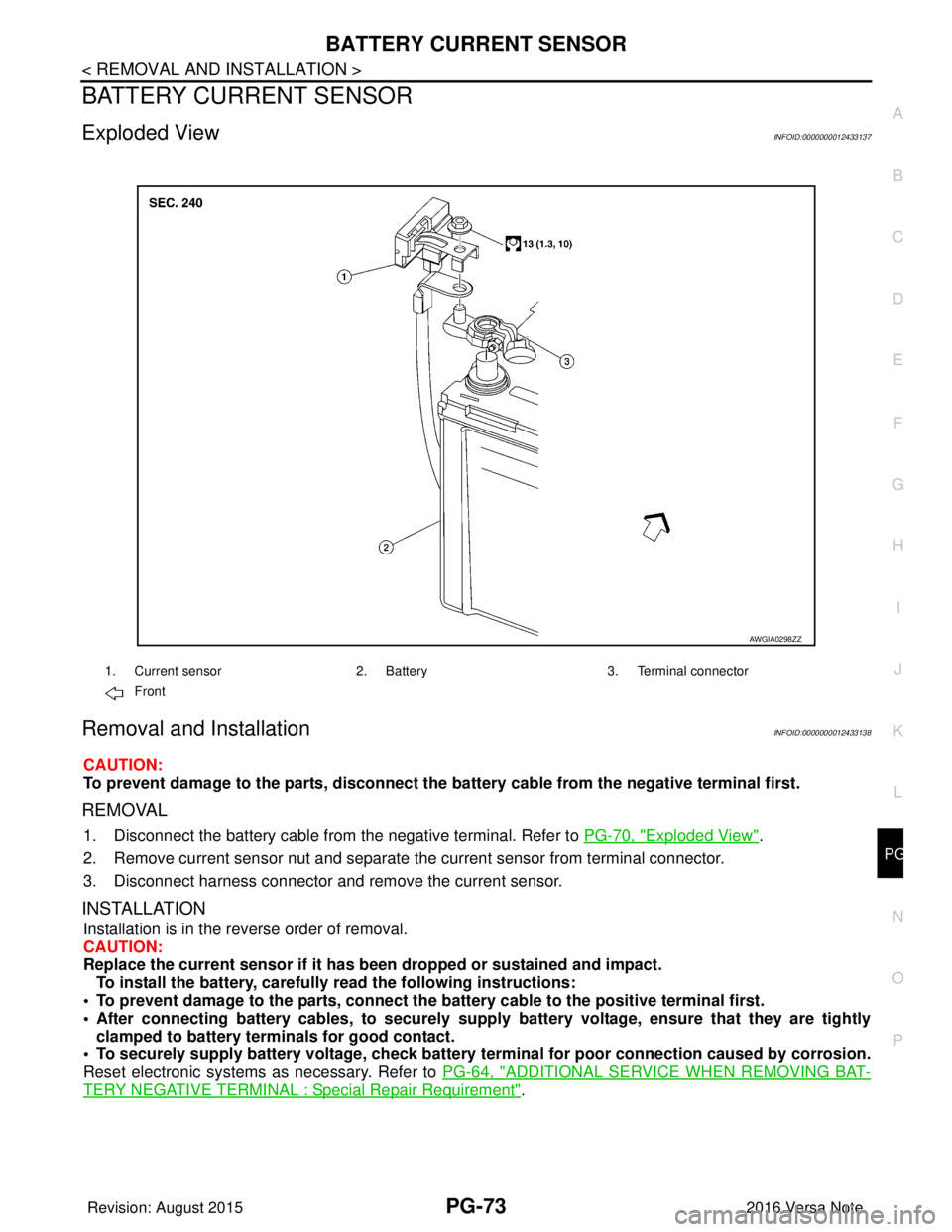
Exploded ViewINFOID:0000000012433137
Removal and InstallationINFOID:0000000012433138
CAUTION:
To prevent damage to the parts, disconnect the battery cable from the negative terminal first.
REMOVAL
1. Disconnect the battery cable from
the negative terminal. Refer to PG-70, "Exploded View".
2. Remove current sensor nut and separate the current sensor from terminal connector.
3. Disconnect harness connector and remove the current sensor.
INSTALLATION
Installation is in the reverse order of removal.
CAUTION:
Replace the current sensor if it has b een dropped or sustained and impact.
To install the battery, carefully read the following instructions:
• To prevent damage to the parts, connect the battery cable to the positive terminal first.
• After connecting battery cables, to securely supp ly battery voltage, ensure that they are tightly
clamped to battery terminals for good contact.
• To securely supply battery voltage, check battery terminal for poor connection caused by corrosion.
Reset electronic systems as necessary. Refer to PG-64, "
ADDITIONAL SERVICE WHEN REMOVING BAT-
TERY NEGATIVE TERMINAL : Special Repair Requirement".
AWGIA0298ZZ
1. Current sensor2. Battery3. Terminal connector
Front
Revision: August 2015 2016 Versa Note
cardiagn.com
Page 2835 of 3641
SE-22
< REMOVAL AND INSTALLATION >
FRONT SEAT
PASSENGER SIDE : Remo val and Installation
INFOID:0000000012432038
WARNING:
• Do not leave any objects (screwdriver s, tools, etc.) on the seat during repair. It can lead to personal
injury if the side air bag module should accidentally deploy.
• Always work from the side or back of th e seatback, do not work in front of seat.
• Do not use air tools or electric tools for servicing the seat assembly.
• Do not drop, tilt, or bump the si de air bag module while installing the seat. Always handle it with
care.
• After the side air bag module inflates, the front seat frame must be replaced.
• Before removing the front seat, tu rn the ignition switch OFF, disconnect both battery cables then
wait at least three minutes.
CAUTION:
When removing and inst alling the seat, use shop cloths to protect components from damage.
REMOVAL
1. Disconnect negative and positive battery terminals, then wait at least three minutes. Refer to PG-70,
"Removal and Installation (Battery)".
2. Slide the seat to the full forward position.
3. Remove the seat rear bolts.
4. Slide the seat to the full rearward position.
5. Remove the seat front bolts.
6. Tilt the seat rearward and disconnect the harness connectors from the seat and remove.
INSTALLATION
Installation is in the reverse order of removal.
WARNING:
• Perform additional services when installing front passenger seat. Refer to SRC-39, "
ZERO POINT
RESET : Description".
• Zero point reset must be performed every time th e front passenger seat is removed from the vehicle.
• Zero point reset is done after the front passenger seat is installed in vehicle and all bolts are tight-
ened to specification.
CAUTION:
Make sure that the seat harness or the floor trim is not damaged during installation.
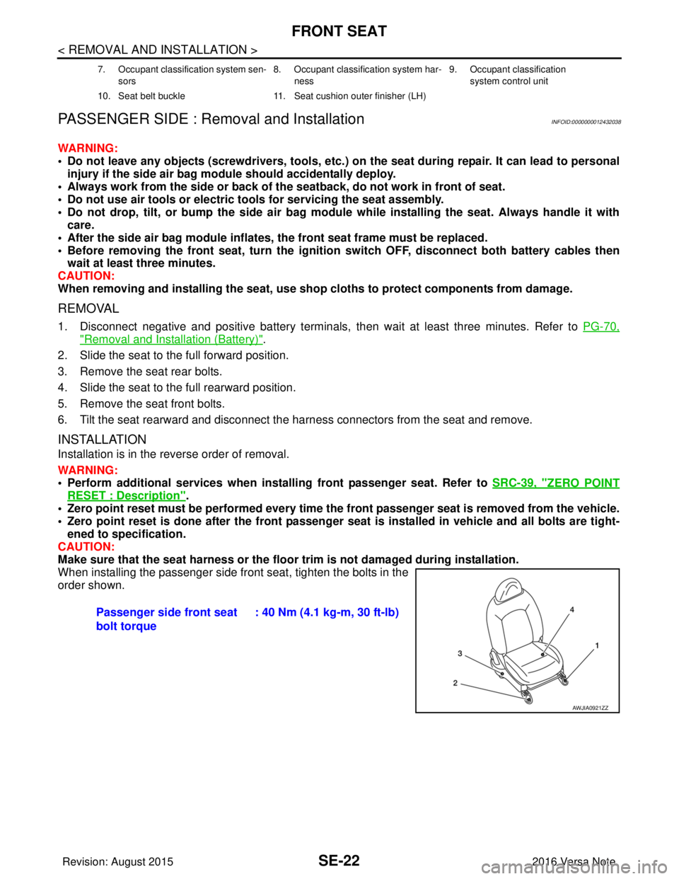
When installing the passenger side front seat, tighten the bolts in the
order shown.
7. Occupant classification system sen-
sors 8. Occupant classification system har-
ness 9. Occupant classification
system control unit
10. Seat belt buckle 11. Seat cushion outer finisher (LH)
Passenger side front seat
bolt torque: 40 Nm (4.1 kg-m, 30 ft-lb)
AWJIA0921ZZ
Revision: August 2015
2016 Versa Note
cardiagn.com
Page 3018 of 3641

SRC-1
RESTRAINTS
C
DE
F
G
I
J
K L
M
SECTION SRC
A
B
SRC
N
O P
CONTENTS
SRS AIRBAG CONTROL SYSTEM
PRECAUTION ....... ........................................4
PRECAUTIONS .............................................. .....4
Precaution for Supplemental Restraint System
(SRS) "AIR BAG" and "SEAT BELT PRE-TEN-
SIONER" ............................................................. ......
4
Service ......................................................................4
SYSTEM DESCRIPTION ..............................5
COMPONENT PARTS ................................... .....5
Component Parts Location .................................. ......5
Driver Air Bag Module ...............................................6
Front Passenger Air Bag Module ..............................6
Front Side Air Bag Module .................................. ......7
Side Curtain Air Bag Module .....................................7
Front Seat Belt Pre-tensioner ....................................7
Air Bag Diagnosis Sensor Unit ..................................7
Crash Zone Sensor ...................................................8
Front Side Air Bag Satellite Sensor ...........................8
Rear Side Air Bag Satellite Sensor ...........................8
Front Door Satellite Sensor .......................................8
SRS Component Connectors ....................................8
SYSTEM .............................................................10
SRS AIR BAG SYSTEM ............................................10
SRS AIR BAG SYSTEM : System Description ... ....10
OCCUPANT CLASSIFICATION SYSTEM ............ ....10
OCCUPANT CLASSIFICATION SYSTEM : Sys-
tem Description .......................................................
11
SEAT BELT WARNING LAMP SYSTEM .............. ....12
SEAT BELT WARNING LAMP SYSTEM : System
Description ..............................................................
12
DIAGNOSIS SYSTEM (AIR BAG) .....................14
Description .......................................................... ....14
On Board Diagnosis Function .................................14
Trouble Diagnosis with CONSULT ..........................16
CONSULT Function (AIR BAG) ..............................16
ECU DIAGNOSIS INFORMATION ..............17
DIAGNOSIS SENSOR UNIT .............................17
DTC Index ........................................................... ....17
Flash Code Index ....................................................21
WIRING DIAGRAM ......................................25
SRS AIR BAG SYSTEM ...................................25
Wiring Diagram .................................................... ....25
BASIC INSPECTION ...................................36
DIAGNOSIS AND REPAIR WORK FLOW .......36
Work Flow ............................................................ ....36
INSPECTION AND ADJUSTMENT ..................39
ADDITIONAL SERVICE WHEN REPLACING
CONTROL UNIT .................................................... ....
39
ADDITIONAL SERVICE WHEN REPLACING
CONTROL UNIT : Description .................................
39
ADDITIONAL SERVICE WHEN REPLACING
CONTROL UNIT : Special Repair Requirement ......
39
ZERO POINT RESET ............................................. ....39
ZERO POINT RESET : Description .........................39
ZERO POINT RESET : Special Repair Require-
ment .........................................................................
39
INTERMITTENT INCIDENT ..............................41
Inspection Procedure ..............................................41
DTC/CIRCUIT DIAGNOSIS .........................42
B0001, B0002 DRIVER AIRBAG MODULE .....42
DTC Logic ............................................................ ....42
Diagnosis Procedure ...............................................43
B0010, B0011 PASSENGER AIRBAG MOD-
ULE ....................................................................
45
DTC Logic ................................................................45
Diagnosis Procedure ...............................................45
Revision: August 2015 2016 Versa Note
cardiagn.com
Page 3056 of 3641
INSPECTION AND ADJUSTMENTSRC-39
< BASIC INSPECTION >
C
DE
F
G
I
J
K L
M A
B
SRC
N
O P
INSPECTION AND ADJUSTMENT
ADDITIONAL SERVICE WHEN REPLACING CONTROL UNIT
ADDITIONAL SERVICE WHEN REPL ACING CONTROL UNIT : Description
INFOID:0000000012430612
Always perform zero point reset using CONSULT when removing and installing the passenger seat or servic-
ing the occupant classification system. If zero point reset is not performed the OCS may not operate normally,
which may increase the risk of serious injury in a collision.
ADDITIONAL SERVICE WHEN REPLACING CONTROL UNIT : Special Repair Re-
quirement
INFOID:0000000012430613
WORK PROCEDURE WHEN REPLACING CONTROL UNIT
1.PERFORM ZERO POINT RESET
Perform zero point reset. Refer to SRC-39, "
ZERO POINT RESET : Special Repair Requirement".
Is zero point reset performed normally?
YES >> INSPECTION END
NO >> Check condition as per the following, and perform zero point reset again. • Passenger seat is occupied by an object.
• Excessive vibration is applied while performing zero point reset.
• Occupant detection system is malfunctioning.NOTE:
If “Incomplete” is displayed on “zero point reset cu rrent status”, zero point reset is not completed
normally. Check the condition as per the following and perform zero point reset again.
• Passenger seat is occupied by an object.
• Excessive vibration is applied while performing zero point reset.
• Occupant detection system is malfunctioning.
ZERO POINT RESET
ZERO POINT RESET : DescriptionINFOID:0000000012430614
Zero point reset is an initializing procedure for occupant detection sensor that must be performed when replac-
ing or removing and installing passenger seat.
If zero point reset is not performed, the initializati on is incomplete and Occupant Detection System does not
operate normally.
NOTE:
• When zero point reset is performed once after removal and installation of passenger seat, CONSULT dis- plays “complete”.
• When reinstalling passenger seat after removal, the initial value for occupant detection sensor changes, and
Occupant Detection System does not operate normally.
• Always perform zero point reset after performing the work as per the following.
- Reinstallation of passenger seat
- Installation of passenger seat that is zero point reset complete
- Installation of passenger seat that is zero point reset in complete
ZERO POINT RESET : Special Repair RequirementINFOID:0000000012430615
1.PERFORM ZERO POINT RESET
1. Perform zero point reset. NOTE:
When performing zero point reset, be careful of the items described as per the following.
• Perform zero point reset after installing passenger seat to the vehicle
• Do not put any objects on passenger seat
• Do not apply excessive vibration to the vehicle
• Do not touch the vehicle
• Do not tilt the vehicle
Revision: August 2015 2016 Versa Note
cardiagn.com