phone NISSAN PATHFINDER 2023 Owners Manual
[x] Cancel search | Manufacturer: NISSAN, Model Year: 2023, Model line: PATHFINDER, Model: NISSAN PATHFINDER 2023Pages: 665, PDF Size: 4.64 MB
Page 4 of 665
The information contained within this supplement revises or adds to the
"Fuel Recommendation" section of the "Technical and consumer information" and the
“Gas station information” section, the "Roof Rack" section of the "Instruments and controls"
section, the "Tire Chains" section of the "Do-It-Yourself" section, and the "Off-Road Mode"
section of the "Monitor, climate, audio, phone and voice recognition system" section for
the 2023 Pathfinder Owner's Manual.
Read carefully and keep in the vehicle.
Printing: JULY 2022
Publication No. SU23EA 1R53U0
OWNER’S MANUAL SUPPLEMENT
Page 11 of 665

NISSAN CARES . . .
Both NISSAN and your NISSAN dealer are dedicated to serving all your automotive needs. Your satisfaction with your vehicle and your
NISSAN dealer are our primary concerns. YourNISSAN dealer is always available to assist you with all your automobile sales and service
needs.
However, if there is something that your
NISSAN dealer cannot assist you with or
you would like to provide NISSAN directly
with comments or questions, please con-
tact the NISSAN Consumer Affairs Depart-
ment using our toll-free number:
For U.S. customers 1-800-NISSAN-1
(1-800-647-7261)
For Canadian customers 1-800-387-0122 The Consumer Affairs Department will ask
for the following information:
– Your name, address, and telephone
number
– Vehicle identification number (attached to the top of the instrument panel on the
driver's side)
– Date of purchase
– Current odometer reading
– Your NISSAN dealer's name
– Your comments or questions
OR You can write to NISSAN with the informa-
tion at:
For U.S. customers
Nissan North America, Inc.
Consumer Affairs Department
P.O. Box 685003
Franklin, TN 37068-5003
or via e-mail at:
[email protected]
For Canadian customers Nissan Canada Inc.
5290 Orbitor Drive
Mississauga, Ontario L4W 4Z5
or via e-mail at:
[email protected]
If you prefer, visit us at:
www.nissanusa.com (for U.S. customers)
or
www.nissan.ca (for Canadian customers)
We appreciate your interest in NISSAN and thank you for buying a quality NISSAN vehicle.
NISSAN CUSTOMER CARE PROGRAM
Page 12 of 665
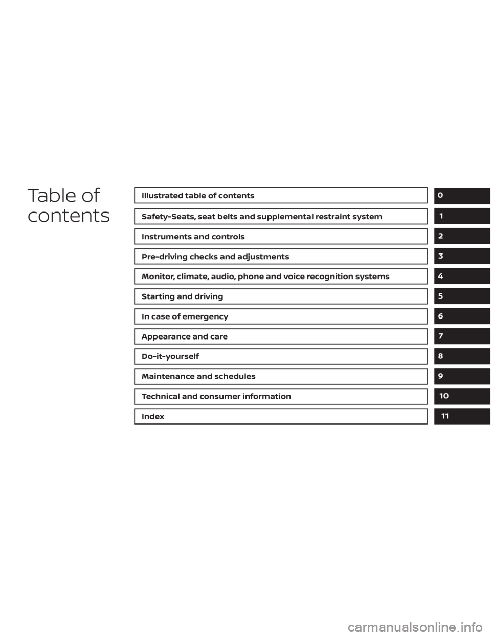
Table of
contentsIllustrated table of contents
Safety-Seats, seat belts and supplemental restraint system
Instruments and controls
Pre-driving checks and adjustments
Monitor, climate, audio, phone and voice recognition systems
Starting and driving
In case of emergency
Appearance and care
Do-it-yourself
Maintenance and schedules
Technical and consumer information
Index
0
1
2
3
4
5
6
7
8
9
10
11
Page 19 of 665
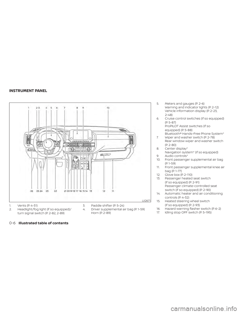
1. Vents (P. 4-31)
2. Headlight/fog light (if so equipped)/turn signal switch (P. 2-82, 2-89) 3. Paddle shif ter (P. 5-24)
4. Driver supplemental air bag (P. 1-59)
Horn (P. 2-89) 5. Meters and gauges (P. 2-6)
Warning and indicator lights (P. 2-12)
Vehicle information display (P. 2-23,
2-48)
6. Cruise control switches (if so equipped)
(P. 5-87)
ProPILOT Assist switches (if so
equipped) (P. 5-88)
Bluetooth® Hands-Free Phone System*
7. Wiper and washer switch (P. 2-78) Rear window wiper and washer switch
(P. 2-80)
8. Center display* Navigation system* (if so equipped)
9. Audio controls*
10. Front passenger supplemental air bag
(P. 1-59)
11. Front passenger supplemental knee air
bag (P. 1-77)
12. Glove box (P. 2-110)
13. Passenger heated seat switch
(if so equipped) (P. 2-91)
Passenger climate-controlled seat
switch (if so equipped) (P. 2-90)
14. Automatic heater and air conditioning
controls (P. 4-32)
15. Heated steering wheel switch
(if so equipped) (P. 2-93)
16. Hazard warning flasher switch (P. 6-2)
17. Idling stop OFF switch (P. 5-195)
LII2671
INSTRUMENT PANEL
0-6Illustrated table of contents
Page 111 of 665
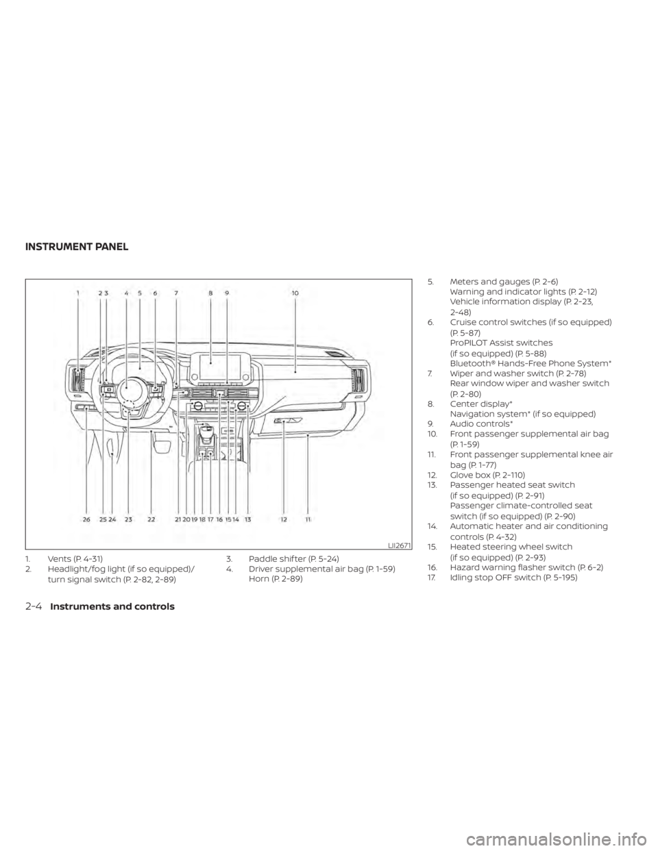
1. Vents (P. 4-31)
2. Headlight/fog light (if so equipped)/turn signal switch (P. 2-82, 2-89) 3. Paddle shif ter (P. 5-24)
4. Driver supplemental air bag (P. 1-59)
Horn (P. 2-89) 5. Meters and gauges (P. 2-6)
Warning and indicator lights (P. 2-12)
Vehicle information display (P. 2-23,
2-48)
6. Cruise control switches (if so equipped)
(P. 5-87)
ProPILOT Assist switches
(if so equipped) (P. 5-88)
Bluetooth® Hands-Free Phone System*
7. Wiper and washer switch (P. 2-78) Rear window wiper and washer switch
(P. 2-80)
8. Center display* Navigation system* (if so equipped)
9. Audio controls*
10. Front passenger supplemental air bag
(P. 1-59)
11. Front passenger supplemental knee air
bag (P. 1-77)
12. Glove box (P. 2-110)
13. Passenger heated seat switch
(if so equipped) (P. 2-91)
Passenger climate-controlled seat
switch (if so equipped) (P. 2-90)
14. Automatic heater and air conditioning
controls (P. 4-32)
15. Heated steering wheel switch
(if so equipped) (P. 2-93)
16. Hazard warning flasher switch (P. 6-2)
17. Idling stop OFF switch (P. 5-195)
LII2671
INSTRUMENT PANEL
2-4Instruments and controls
Page 204 of 665
–– Speed Limit Sign
–– Audio
–– TEL/SMS
• Reset
NOTE:
• Emergency information may display even if the HUD is turned off.
• If the HUD is turned off, the settings items are grayed out and cannot be
modified until the HUD is turned back
on.
This product includes the following
sof tware.
(1) Panasonic Corporation or sof tware de-
veloped for Panasonic Corporation
(2) Third-party sof tware licensed to Pana-
sonic Corporation
(3) Open source sof tware
Regarding (3) Open source sof tware, it in-
cludes open source sof tware (OSS), includ-
ing various sof tware to which license infor-
mation applies.
Refer to the license web site at:
http://car.panasonic.jp/oss/i02lln39.
DRIVER ASSISTANCE/NAVIGATION
LINKING
The HUD will display driver assistance and
navigation information.
The driver assistance display will show
warning situations for the following sys-
tems:
• Automatic Emergency Braking (AEB) with Pedestrian Detection
• Lane Departure Warning (LDW)
• Intelligent Forward Collision Warning (IFCW)
• Hands-free warning (for vehicles with ProPILOT Assist) (if so equipped)
• Traffic Sign Recognition (TSR) (if so equipped)
The navigation system linking display will
show the following items:
• Intersection names
• Arrows indicating turning direction
• Distance to the next intersection The Audio System linking display will show
the following items:
• Songs
• Radio stations
The TEL/SMS linking display will show the
following items:
• Caller’s name or phone number
Instruments and controls2-97
Page 208 of 665
NOTE:
If “Alert Only ” setting is selected, the
message alert will still be shown in the
vehicle information display but the horn
will not sound.
WARNING
• If the driver selects “Disable Alert”, no
audible alert will be provided regard-
less of rear door open/close status.
• There may be times when there is an
object or passenger in the rear
seat(s) but the audible alert does not
sound. For example, this may occur if
rear seat passengers enter or exit the
vehicle during a trip.
• The system does not directly detect
objects or passengers in the rear
seat(s). Instead, it can detect when a
rear door is opened and closed, indi-
cating that there may be something
in the rear seat(s).
NOTE:
There may be times when the horn
sounds but there are no objects or pas-
sengers in the rear seat(s). For additional information, see “Rear Door
Alert is activated” (P. 2-66).
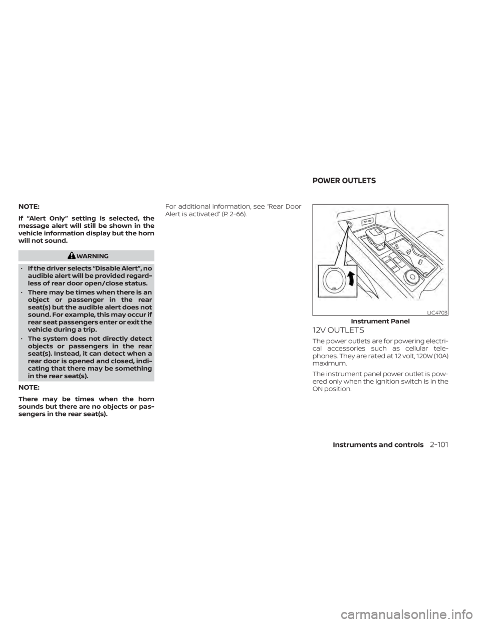
12V OUTLETS
The power outlets are for powering electri-
cal accessories such as cellular tele-
phones. They are rated at 12 volt, 120W (10A)
maximum.
The instrument panel power outlet is pow-
ered only when the ignition switch is in the
ON position.
LIC4703
Instrument Panel
POWER OUTLETS
Instruments and controls2-101
Page 211 of 665
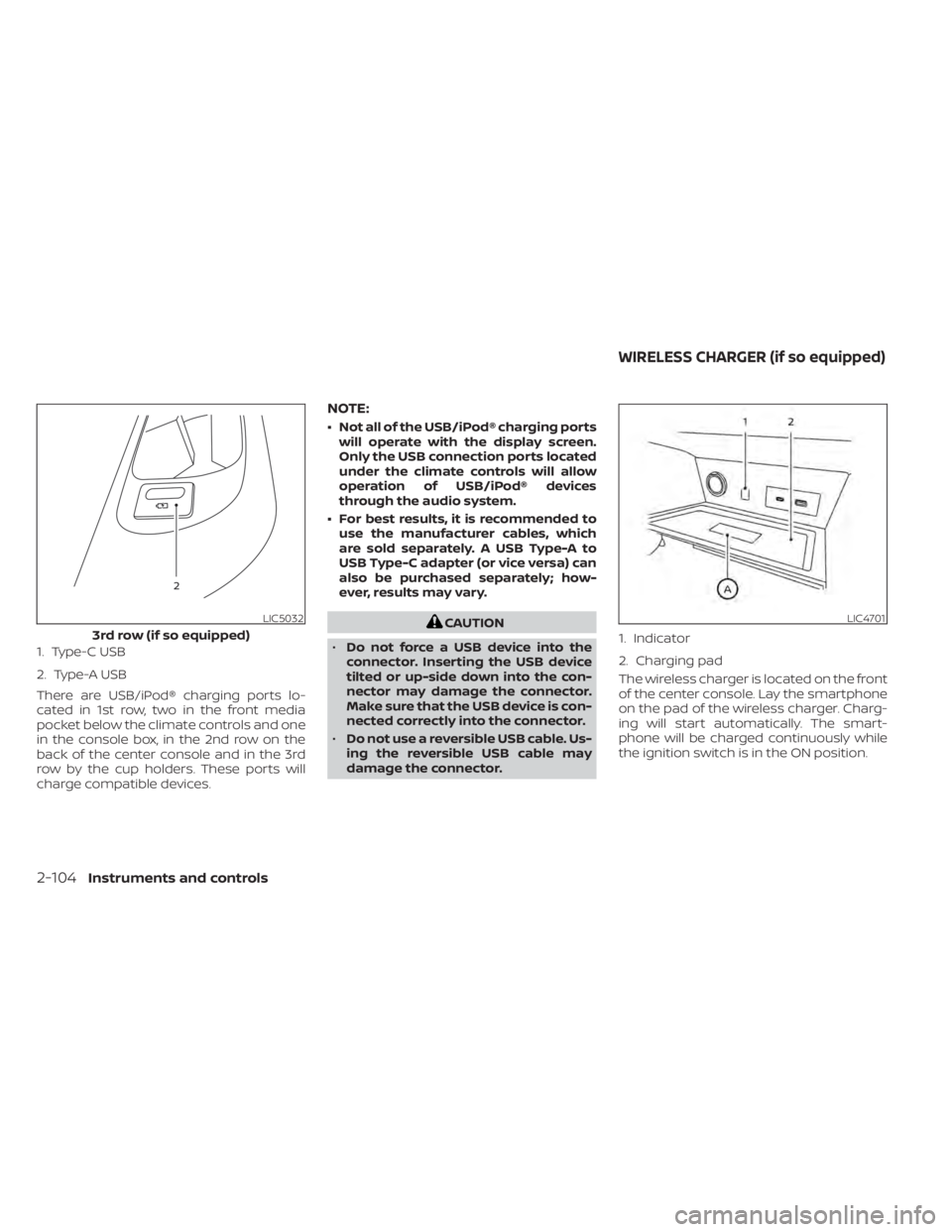
1. Type-C USB
2. Type-A USB
There are USB/iPod® charging ports lo-
cated in 1st row, two in the front media
pocket below the climate controls and one
in the console box, in the 2nd row on the
back of the center console and in the 3rd
row by the cup holders. These ports will
charge compatible devices.
NOTE:
• Not all of the USB/iPod® charging portswill operate with the display screen.
Only the USB connection ports located
under the climate controls will allow
operation of USB/iPod® devices
through the audio system.
• For best results, it is recommended to use the manufacturer cables, which
are sold separately. A USB Type-A to
USB Type-C adapter (or vice versa) can
also be purchased separately; how-
ever, results may vary.
CAUTION
• Do not force a USB device into the
connector. Inserting the USB device
tilted or up-side down into the con-
nector may damage the connector.
Make sure that the USB device is con-
nected correctly into the connector.
• Do not use a reversible USB cable. Us-
ing the reversible USB cable may
damage the connector. The wireless charger is located on the front
of the center console. Lay the smartphone
on the pad of the wireless charger. Charg-
ing will start automatically. The smart-
phone will be charged continuously while
the ignition switch is in the ON position.LIC5032
3rd row (if so equipped)
LIC4701
1. Indicator
2. Charging pad
WIRELESS CHARGER (if so equipped)
2-104Instruments and controls
Page 212 of 665
WARNING
• Never put metallic materials be-
tween the wireless charger and a
smartphone.
• Those who use a pacemaker or other
medical equipment should contact
the electric medical equipment
manufacturer for the possible influ-
ences before use.
• Never put cloth over the smartphone
during charging process.
• Never charge a smartphone when it
is wet.
• Never put metallic materials or small
goods such as a cigarette lighter, In-
telligent Key or memory drive.
CAUTION
• Do not put an RFID/NFC/credit card
between the wireless charger and a
smartphone. This could cause data
corruption in the card.
• Do not use the wireless charger with
dust accumulated or dirt on the pad.
• Do not hit the surface of the wireless
charger. •
Do not spill liquid (water, drinks, etc.)
on the charging pad.
• Do not use grease, oil or alcohol for
cleaning charging pad.
WIRELESS CHARGER INDICATOR
The indicator(1)willil luminate in orange
when the charging process is started.
When the charging has completed, the in-
dicator illuminates in green.
If a malfunction occurs or the charging
process has stopped, the indicator will
blink in orange for 8 seconds then turn off.
WIRELESS CHARGER OPERATION
To use the wireless charger, it is necessary
to seat the smartphone well within the
charging pad. To maximize charging per-
formance, ensure the smartphone is fully
seated on the center of the charging pad
over the "Qi" logo
OA. Because the location
of the power receiver may vary depending
on the smartphone, you will need to try and
find the area that suits your smartphone.
Because some smartphone cases or ac-
cessories may adversely affect charging,
remove them before wireless charging.
Turn off the vibration function of the smart-
phone before wireless charging.
NOTE:
• Only a Qi compatible smartphone can
be used.
• The smartphone may be warmed dur-
ing charging process and the charging
may stop by the protection function of
the wireless charger. This is not a mal-
function. If this occurs, restart charging
af ter the smartphone cooled down.
The indicator will blink in orange then
turn off.
• The wireless charging process may be
stopped by the status of the smart-
phone (battery temperature, etc.).
• If a radio noise interference occurs dur-
ing charging process, put the smart-
phone onto the center (“Qi” logo) posi-
tion of the wireless charger.
• The wireless charging process will stop
during process of searching the Intelli-
gent Key.
• The wireless charging process will not
be started when a USB (Universal Serial
Bus) cable is connected to the smart-
phone. The indicator may illuminate in
orange or blink if the smartphone is
put on the wireless charger with a USB
cable connected. However, charging is
not performed.
Instruments and controls2-105
Page 213 of 665
•Depending on the type of the smart-
phone, the indicator may remain illu-
minated in orange even when the
charging process has been completed.
FCC ID: BEJWC500MNM
IC: 2703H-WC500MNM
This device complies with part 15 of the
FCC Rules and RSS-Gen of IC Rules.
Operation is subject to the following two
conditions:
(1) This device may not cause harmful
interference, and
(2) This device must accept any interfer-
ence received, including interference
that may cause undesired operation.
Changes or modifications not expressly
approved by the party responsible for
compliance could void the user’s author-
ity to operate the equipment.
RF Radiation Exposure Statement: This
equipment complies with FCC RF Radia-
tion exposure limits set forth for an un-
controlled environment.
This device and its antenna must not be
co-located or operating in conjunction
with any other antenna or transmitter.
This equipment should be installed and
operated with a minimum distance of
15cm between the radiator and your
body. ISED Compliance Statement
This device complies with RSS-Gen of IC
Rules
Operation is subject to the following two
conditions:
(1) This device may not cause harmful
interference, and
(2) This device must accept any interfer-
ence received, including interference
that may cause undesired operation.
Changes or modifications made to this
device, not expressly approved by LG Ve-
hicle Components Company, will void the
user’s authority to operate the
equipment.
ISED RF Radiation Exposure Statement:
This equipment complies with ISED RF
Radiation exposure limits set forth for an
uncontrolled environment. This device
and its antenna must not be co-located
or operating in conjunction with any
other antenna or transmitter. This
equipment should be installed to oper-
ate with a minimum distance of 15 cm
between the radiator and the end-user’s
body and arms.
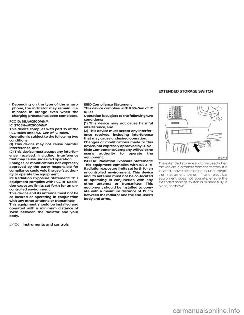
The extended storage switch is used when
the vehicle is in transit from the factory. It is
located above the brake pedal underneath
the instrument panel. If any electrical
equipment does not operate, ensure the
extended storage switch is pushed fully in
place, as shown.
LIC4753
EXTENDED STORAGE SWITCH
2-106Instruments and controls