Back NISSAN PATROL 1998 Y61 / 5.G Electrical System User Guide
[x] Cancel search | Manufacturer: NISSAN, Model Year: 1998, Model line: PATROL, Model: NISSAN PATROL 1998 Y61 / 5.GPages: 326, PDF Size: 11.36 MB
Page 97 of 326
System Description
Front interior room lamp timer is controlled by smart entrance control unit while interior room lamp switch is
in the ``DOOR'' position.
Smart entrance control unit does not control rear interior room lamp.
TIMER OPERATION
Interior room lamp timer keeps interior room lamp illuminated for about 15 seconds when:
+driver's door is unlocked while key is out of ignition key cylinder,
+key is withdrawn from ignition key cylinder while driver's door is closed, and
+driver's door is opened and then closed while ignition switch is not in the ``ON'' position.
The timer is cancelled, and interior room lamp turns off when:
+driver's door is locked, or
+ignition switch is turned ``ON''.
ON-OFF CONTROL
When the front driver side door, front passenger side door, rear LH door, rear RH door or back door is opened,
interior room lamp turns on.
When driver side door is opened and then closed while ignition switch is not in the ON position, interior room
lamp timer operates. (Timer does not operate when doors other than the driver side door is opened and
closed.)
INTERIOR ROOM LAMP Ð With Timer Ð
EL-93
Page 178 of 326
NATS Audio Link/LHD
DESCRIPTION
The link with the NATS IMMU implies that the radio can basically only be operated if connected to the match-
ing NATS IMMU to which the radio was initially ®tted on the production line.
Since radio operation is impossible after the link with the NATS is disrupted theft of the radio unit is basically
useless since special equipment is required to reset the radio.
Initialisation process for radios that are linked to the NATS IMMU
New radios will be delivered to the factories in the ``NEW'' state, i.e. ready to be linked with the vehicle's NATS.
When the radio in ``NEW'' state is ®rst switched on at the factory, it will start up communication with the vehi-
cle's immobiliser control unit (IMMU) and send a code (the ``Radio Code'') to the IMMU. The IMMU will then
store this code, which is unique to each radio, in its (permanent) memory.
Upon receipt of the code by the IMMU, the NATS will con®rm correct receipt of the radio code to the radio.
Hereafter, the radio will operate as normal.
During the initialisation process, ``NEW'' is displayed on the radio display. Normally though, communication
between Radio and IMMU takes such a short time (300 ms) that the radio seems to switch on directly with-
out showing ``NEW'' on its display.
Normal operation
Each time the radio is switched on afterwards, the radio code will be veri®ed between the radio unit and the
NATS before the radio becomes operational. During the code veri®cation process, ``WAIT'' is shown on the
radio display. Again, the communication takes such a short time (300 ms) that the radio seems to switch on
directly without showing ``WAIT'' on its display.
When the radio is locked
In case of a radio being linked with the vehicle's NATS (immobiliser system), disconnection of the link between
the radio and the IMMU will cause the radio to switch into the lock (``SECURE'') mode in which the radio unit
is fully inoperative. Hence, repair of the radio is basically impossible, unless the radio is reset to the ``NEW''
state for which special decoding equipment is required.
Both Blaupunkt and Clarion have provided their authorized service representatives with so called ``decoder
boxes'' which can bring the radio unit back to the ``NEW'' state, enabling the radio to be switched on after which
repair can be carried out. Subsequently, when the repaired radio is delivered to the ®nal user again, it will be
in the ``NEW'' state as to enable re-linking the radio to the vehicle's immobiliser system. As a result of the
above, repair of the radio can only be done by an authorized Blaupunkt or Clarion representative.
Note:
Radio manufacturer of Nissan Y61 models for Europe is ``Clarion''.
SERVICE PROCEDURE
Item Service procedure Description
Battery disconnection No additional action required. Ð
Radio needs repair Repair needs to be done by authorized represen-
tative of radio manufacturer since radio cannot
be operated unless it is reset to NEW state,
using special decoding equipment.Ð
Replacement of radio by new
partNo additional action required. Radio is delivered in NEW state.
Transferring radio to another
vehicle/replacement of radio
by an ``old'' partRadio needs to be reset to NEW state by autho-
rized representative of radio manufacturer.Ð
Replacement of IMMU by
new partNo additional action required. The new IMMU will be recognized by the radio
since a `blank' code is stored in the memory of
the IMMU. In case the radio recognizes this
`blank' code, it will request for input of the correct
CATS code after which the radio will switch back
to the initialisation process.
AUDIO
EL-174
Page 216 of 326
System Description
OUTLINE
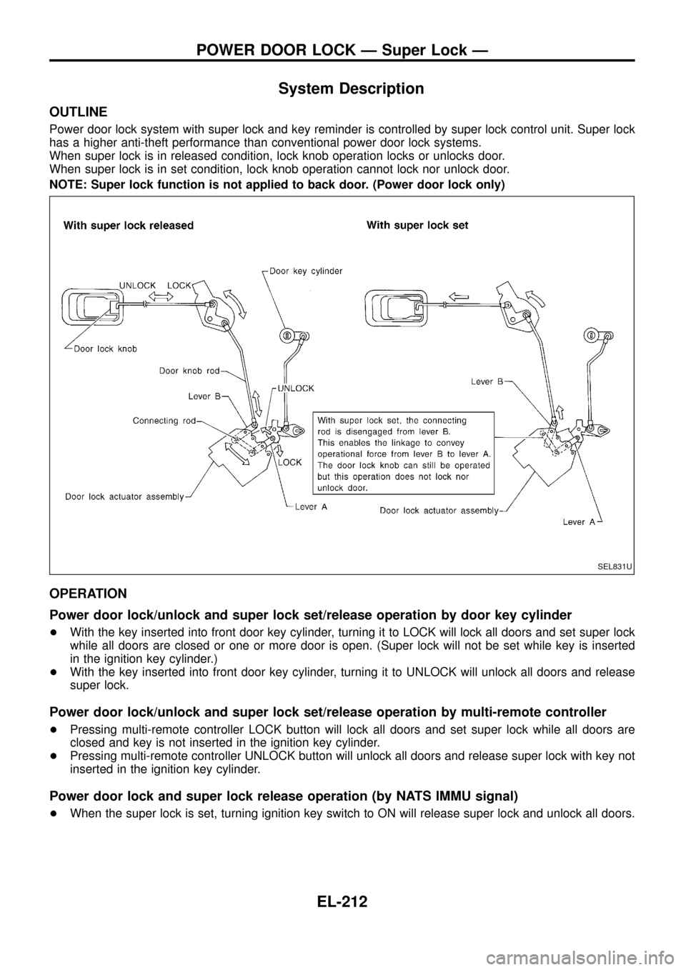
Power door lock system with super lock and key reminder is controlled by super lock control unit. Super lock
has a higher anti-theft performance than conventional power door lock systems.
When super lock is in released condition, lock knob operation locks or unlocks door.
When super lock is in set condition, lock knob operation cannot lock nor unlock door.
NOTE: Super lock function is not applied to back door. (Power door lock only)
OPERATION
Power door lock/unlock and super lock set/release operation by door key cylinder
+With the key inserted into front door key cylinder, turning it to LOCK will lock all doors and set super lock
while all doors are closed or one or more door is open. (Super lock will not be set while key is inserted
in the ignition key cylinder.)
+With the key inserted into front door key cylinder, turning it to UNLOCK will unlock all doors and release
super lock.
Power door lock/unlock and super lock set/release operation by multi-remote controller
+Pressing multi-remote controller LOCK button will lock all doors and set super lock while all doors are
closed and key is not inserted in the ignition key cylinder.
+Pressing multi-remote controller UNLOCK button will unlock all doors and release super lock with key not
inserted in the ignition key cylinder.
Power door lock and super lock release operation (by NATS IMMU signal)
+When the super lock is set, turning ignition key switch to ON will release super lock and unlock all doors.
SEL831U
POWER DOOR LOCK Ð Super Lock Ð
EL-212
Page 232 of 326
DIAGNOSTIC PROCEDURE 3
(Door lock actuator check)
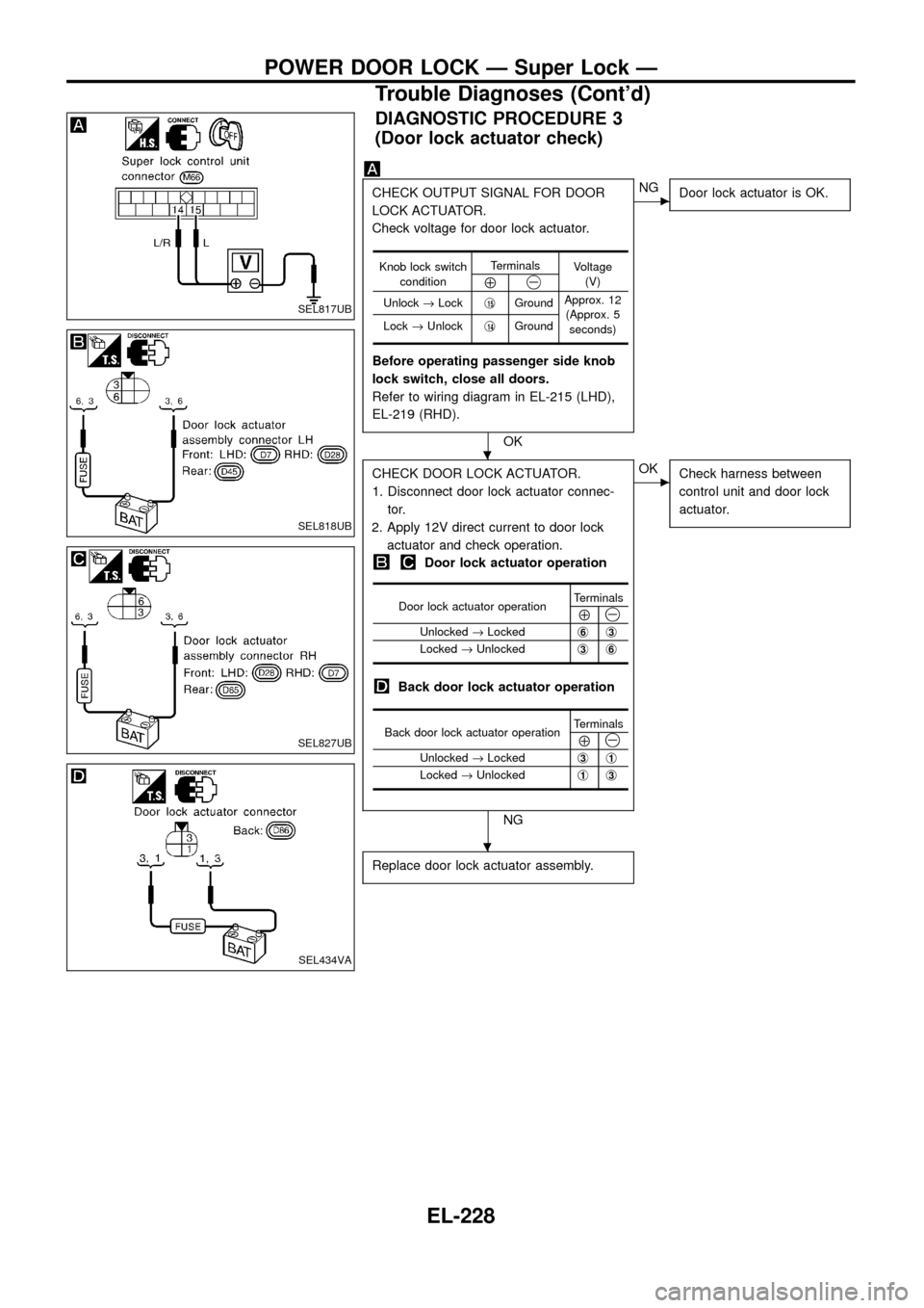
CHECK OUTPUT SIGNAL FOR DOOR
LOCK ACTUATOR.
Check voltage for door lock actuator.
Before operating passenger side knob
lock switch, close all doors.
Refer to wiring diagram in EL-215 (LHD),
EL-219 (RHD).
OK
cNG
Door lock actuator is OK.
CHECK DOOR LOCK ACTUATOR.
1. Disconnect door lock actuator connec-
tor.
2. Apply 12V direct current to door lock
actuator and check operation.
Door lock actuator operation
Back door lock actuator operation
NG
cOK
Check harness between
control unit and door lock
actuator.
Replace door lock actuator assembly.
Knob lock switch
conditionTerminals
Voltage
(V)
Å@
Unlock®Lockj15GroundApprox. 12
(Approx. 5
seconds) Lock®Unlockj
14Ground
Door lock actuator operationTerminalsÅ@Unlocked®Lockedj6j3
Locked®Unlockedj3j6
Back door lock actuator operationTerminalsÅ@Unlocked®Lockedj3j1
Locked®Unlockedj1j3
SEL817UB
SEL818UB
SEL827UB
SEL434VA
.
.
POWER DOOR LOCK Ð Super Lock Ð
Trouble Diagnoses (Cont'd)
EL-228
Page 317 of 326
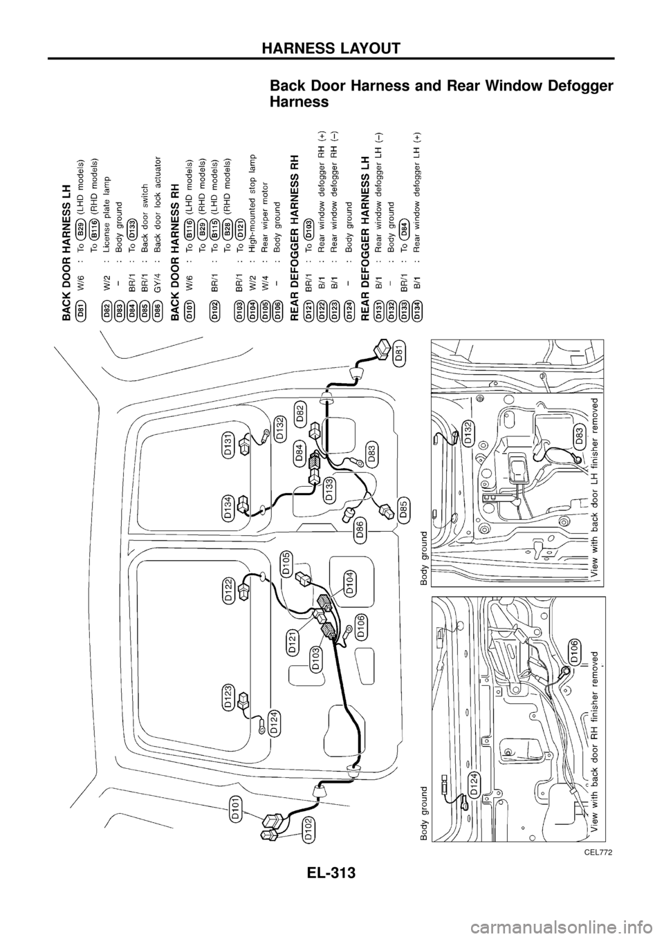
Back Door Harness and Rear Window Defogger
Harness
CEL772
HARNESS LAYOUT
EL-313
Page 318 of 326
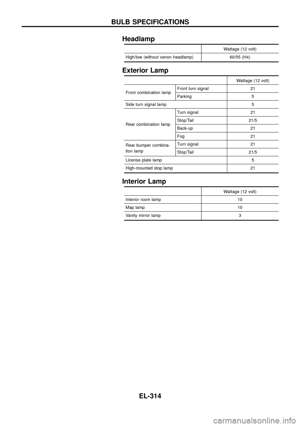
Headlamp
Wattage (12 volt)
High/low (without xenon headlamp) 60/55 (H4)
Exterior Lamp
Wattage (12 volt)
Front combination lampFront turn signal 21
Parking 5
Side turn signal lamp 5
Rear combination lampTurn signal 21
Stop/Tail 21/5
Back-up 21
Fog 21
Rear bumper combina-
tion lampTurn signal 21
Stop/Tail 21/5
License plate lamp 5
High-mounted stop lamp 21
Interior Lamp
Wattage (12 volt)
Interior room lamp 10
Map lamp 10
Vanity mirror lamp 3
BULB SPECIFICATIONS
EL-314
Page 319 of 326
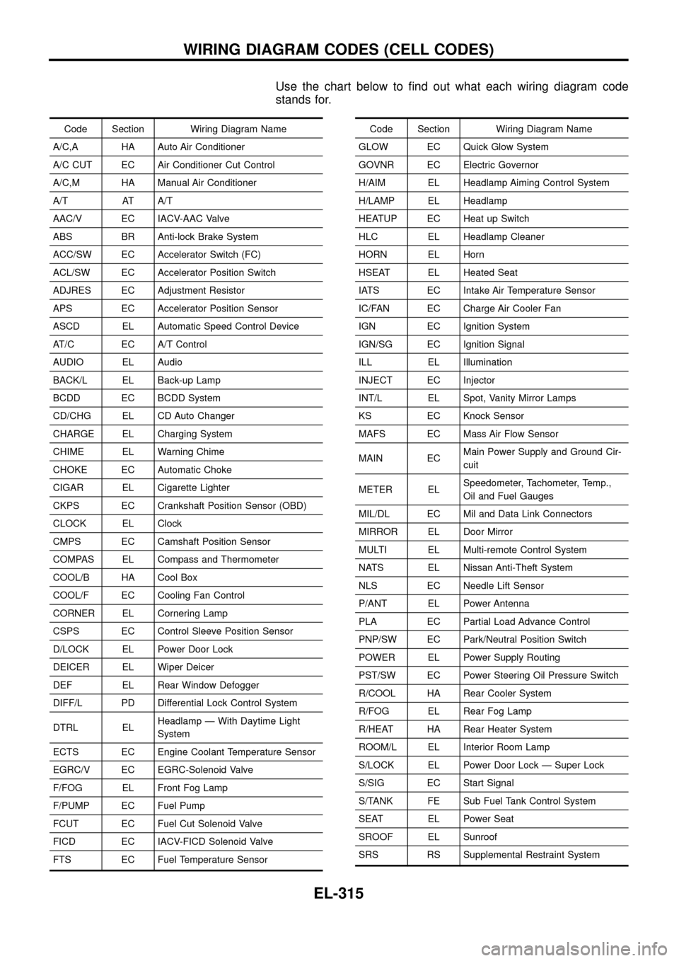
Use the chart below to ®nd out what each wiring diagram code
stands for.
Code Section Wiring Diagram Name
A/C,A HA Auto Air Conditioner
A/C CUT EC Air Conditioner Cut Control
A/C,M HA Manual Air Conditioner
A/T AT A/T
AAC/V EC IACV-AAC Valve
ABS BR Anti-lock Brake System
ACC/SW EC Accelerator Switch (FC)
ACL/SW EC Accelerator Position Switch
ADJRES EC Adjustment Resistor
APS EC Accelerator Position Sensor
ASCD EL Automatic Speed Control Device
AT/C EC A/T Control
AUDIO EL Audio
BACK/L EL Back-up Lamp
BCDD EC BCDD System
CD/CHG EL CD Auto Changer
CHARGE EL Charging System
CHIME EL Warning Chime
CHOKE EC Automatic Choke
CIGAR EL Cigarette Lighter
CKPS EC Crankshaft Position Sensor (OBD)
CLOCK EL Clock
CMPS EC Camshaft Position Sensor
COMPAS EL Compass and Thermometer
COOL/B HA Cool Box
COOL/F EC Cooling Fan Control
CORNER EL Cornering Lamp
CSPS EC Control Sleeve Position Sensor
D/LOCK EL Power Door Lock
DEICER EL Wiper Deicer
DEF EL Rear Window Defogger
DIFF/L PD Differential Lock Control System
DTRL ELHeadlamp Ð With Daytime Light
System
ECTS EC Engine Coolant Temperature Sensor
EGRC/V EC EGRC-Solenoid Valve
F/FOG EL Front Fog Lamp
F/PUMP EC Fuel Pump
FCUT EC Fuel Cut Solenoid Valve
FICD EC IACV-FICD Solenoid Valve
FTS EC Fuel Temperature SensorCode Section Wiring Diagram Name
GLOW EC Quick Glow System
GOVNR EC Electric Governor
H/AIM EL Headlamp Aiming Control System
H/LAMP EL Headlamp
HEATUP EC Heat up Switch
HLC EL Headlamp Cleaner
HORN EL Horn
HSEAT EL Heated Seat
IATS EC Intake Air Temperature Sensor
IC/FAN EC Charge Air Cooler Fan
IGN EC Ignition System
IGN/SG EC Ignition Signal
ILL EL Illumination
INJECT EC Injector
INT/L EL Spot, Vanity Mirror Lamps
KS EC Knock Sensor
MAFS EC Mass Air Flow Sensor
MAIN ECMain Power Supply and Ground Cir-
cuit
METER ELSpeedometer, Tachometer, Temp.,
Oil and Fuel Gauges
MIL/DL EC Mil and Data Link Connectors
MIRROR EL Door Mirror
MULTI EL Multi-remote Control System
NATS EL Nissan Anti-Theft System
NLS EC Needle Lift Sensor
P/ANT EL Power Antenna
PLA EC Partial Load Advance Control
PNP/SW EC Park/Neutral Position Switch
POWER EL Power Supply Routing
PST/SW EC Power Steering Oil Pressure Switch
R/COOL HA Rear Cooler System
R/FOG EL Rear Fog Lamp
R/HEAT HA Rear Heater System
ROOM/L EL Interior Room Lamp
S/LOCK EL Power Door Lock Ð Super Lock
S/SIG EC Start Signal
S/TANK FE Sub Fuel Tank Control System
SEAT EL Power Seat
SROOF EL Sunroof
SRS RS Supplemental Restraint System
WIRING DIAGRAM CODES (CELL CODES)
EL-315