NISSAN PATROL 1998 Y61 / 5.G Clutch Workshop Manual
Manufacturer: NISSAN, Model Year: 1998, Model line: PATROL, Model: NISSAN PATROL 1998 Y61 / 5.GPages: 17, PDF Size: 0.49 MB
Page 1 of 17

CLUTCH
SECTION
CL
CONTENTS
PRECAUTIONS AND PREPARATION............................1
Precautions ..................................................................1
Special Service Tools ..................................................1
Commercial Service Tools ...........................................2
NOISE, VIBRATION AND HARSHNESS (NVH)
TROUBLESHOOTING.....................................................3
NVH Troubleshooting Chart.........................................3
CLUTCH SYSTEM...........................................................4
INSPECTION AND ADJUSTMENT.................................5
Adjusting Clutch Pedal ................................................5
Air Bleeding Procedure................................................6HYDRAULIC CLUTCH CONTROL.................................7
Clutch Master Cylinder ................................................7
Clutch Operating Cylinder ...........................................8
Clutch Booster .............................................................9
CLUTCH RELEASE MECHANISM............................... 11
CLUTCH DISC AND CLUTCH COVER........................13
Clutch Disc.................................................................13
Clutch Cover and Flywheel .......................................14
SERVICE DATA AND SPECIFICATIONS (SDS)..........16
General Speci®cations ...............................................16
Inspection and Adjustment ........................................16
CL
Page 2 of 17

Precautions
+Recommended ¯uid is brake ¯uid ``DOT 3''.
+Do not reuse drained brake ¯uid.
+Be careful not to splash brake ¯uid on painted areas.
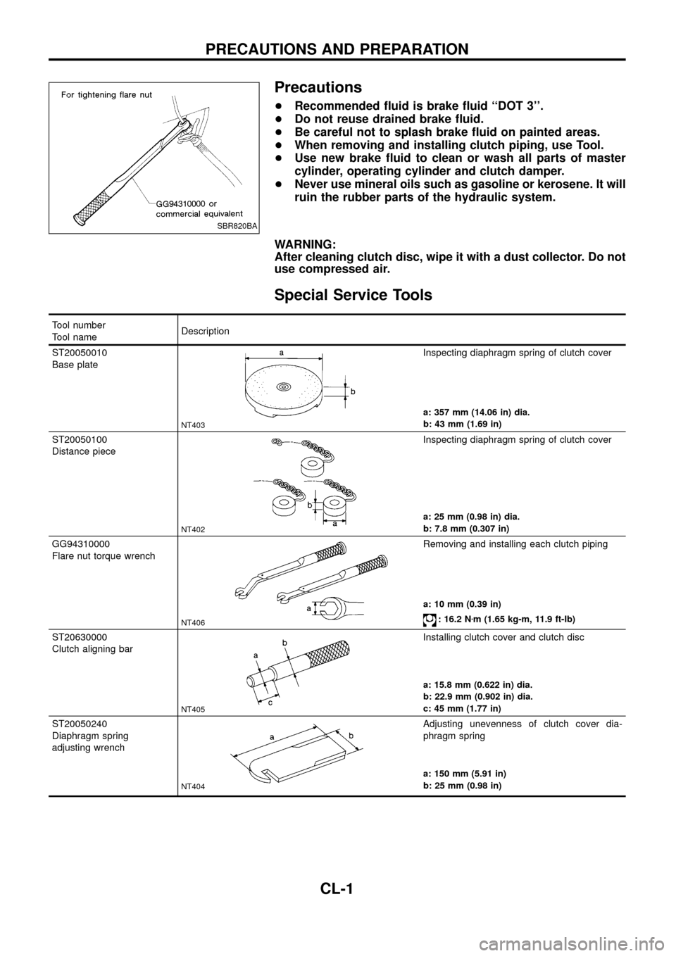
+When removing and installing clutch piping, use Tool.
+Use new brake ¯uid to clean or wash all parts of master
cylinder, operating cylinder and clutch damper.
+Never use mineral oils such as gasoline or kerosene. It will
ruin the rubber parts of the hydraulic system.
WARNING:
After cleaning clutch disc, wipe it with a dust collector. Do not
use compressed air.
Special Service Tools
Tool number
Tool nameDescription
ST20050010
Base plate
NT403
Inspecting diaphragm spring of clutch cover
a: 357 mm (14.06 in) dia.
b: 43 mm (1.69 in)
ST20050100
Distance piece
NT402
Inspecting diaphragm spring of clutch cover
a: 25 mm (0.98 in) dia.
b: 7.8 mm (0.307 in)
GG94310000
Flare nut torque wrench
NT406
Removing and installing each clutch piping
a: 10 mm (0.39 in)
: 16.2 Nzm (1.65 kg-m, 11.9 ft-lb)
ST20630000
Clutch aligning bar
NT405
Installing clutch cover and clutch disc
a: 15.8 mm (0.622 in) dia.
b: 22.9 mm (0.902 in) dia.
c: 45 mm (1.77 in)
ST20050240
Diaphragm spring
adjusting wrench
NT404
Adjusting unevenness of clutch cover dia-
phragm spring
a: 150 mm (5.91 in)
b: 25 mm (0.98 in)
SBR820BA
PRECAUTIONS AND PREPARATION
CL-1
Page 3 of 17

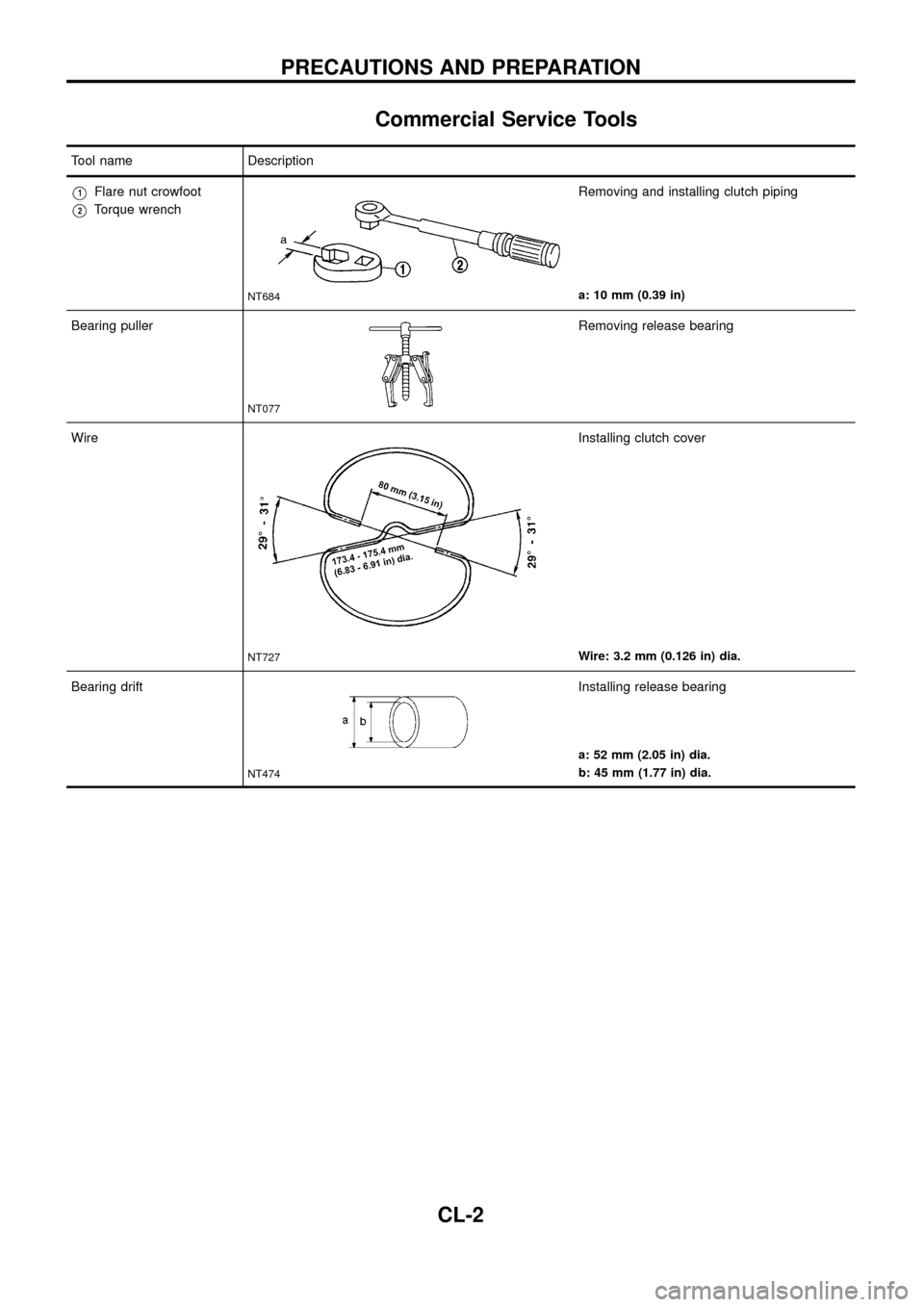
Commercial Service Tools
Tool name Description
V1Flare nut crowfoot
V2Torque wrench
NT684
Removing and installing clutch piping
a: 10 mm (0.39 in)
Bearing puller
NT077
Removing release bearing
Wire
NT727
Installing clutch cover
Wire: 3.2 mm (0.126 in) dia.
Bearing drift
NT474
Installing release bearing
a: 52 mm (2.05 in) dia.
b: 45 mm (1.77 in) dia.
PRECAUTIONS AND PREPARATION
CL-2
Page 4 of 17

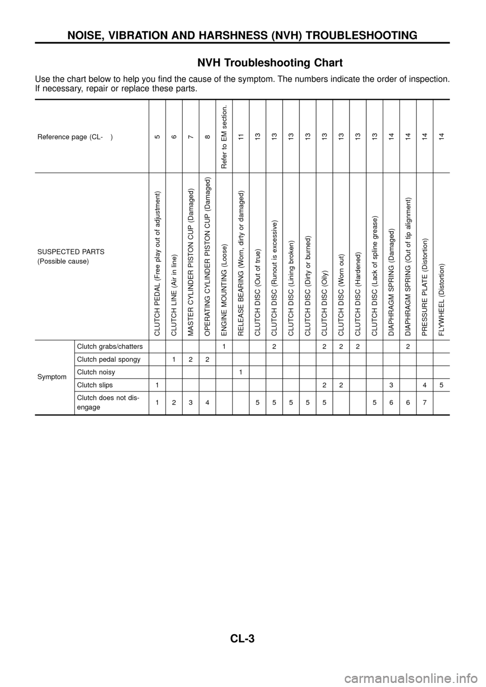
NVH Troubleshooting Chart
Use the chart below to help you ®nd the cause of the symptom. The numbers indicate the order of inspection.
If necessary, repair or replace these parts.
Reference page (CL- )5
6
7
8
Refer to EM section.
11
13
13
13
13
13
13
13
13
14
14
14
14
SUSPECTED PARTS
(Possible cause)
CLUTCH PEDAL (Free play out of adjustment)
CLUTCH LINE (Air in line)
MASTER CYLINDER PISTON CUP (Damaged)
OPERATING CYLINDER PISTON CUP (Damaged)
ENGINE MOUNTING (Loose)
RELEASE BEARING (Worn, dirty or damaged)
CLUTCH DISC (Out of true)
CLUTCH DISC (Runout is excessive)
CLUTCH DISC (Lining broken)
CLUTCH DISC (Dirty or burned)
CLUTCH DISC (Oily)
CLUTCH DISC (Worn out)
CLUTCH DISC (Hardened)
CLUTCH DISC (Lack of spline grease)
DIAPHRAGM SPRING (Damaged)
DIAPHRAGM SPRING (Out of tip alignment)
PRESSURE PLATE (Distortion)
FLYWHEEL (Distortion)
SymptomClutch grabs/chatters 1 2 2 2 2 2
Clutch pedal spongy 1 2 2
Clutch noisy 1
Clutch slips 1 2 2 3 4 5
Clutch does not dis-
engage1234 55555 5667
NOISE, VIBRATION AND HARSHNESS (NVH) TROUBLESHOOTING
CL-3
Page 5 of 17

SCL768
CLUTCH SYSTEM
CL-4
Page 6 of 17

Adjusting Clutch Pedal
1. Adjust pedal height with pedal stopper.
Pedal height ``H*'':
195 - 205 mm (7.68 - 8.07 in)
*: Measured from surface of dash reinforcement panel to
pedal pad
2. Adjust pedal free play with master cylinder push rod or clutch
booster input rod. Then tighten lock nut.
Pedal free play ``A'':
1.0 - 3.0 mm (0.039 - 0.118 in)
Pedal free play means the following total measured at position
of pedal pad:
+Play due to clevis pin and clevis pin hole in clutch pedal.
+Play due to piston and push rod.
+Push or step on clutch pedal until resistance is felt, and check
the distance the pedal moves.
SCL788
SCL702
INSPECTION AND ADJUSTMENT
CL-5
Page 7 of 17

Air Bleeding Procedure
1. Bleed air from clutch operating cylinder according to the follow-
ing procedure.
Carefully monitor ¯uid level at master cylinder during bleeding
operation.
a. Top up reservoir with recommended brake ¯uid.
b. Connect a transparent vinyl tube to air bleeder valve.
c. Slowly depress clutch pedal to its full stroke and release it
completely. Repeat this operation several times at 2 to 3 sec-
ond intervals.
d. Hold clutch pedal depressed, open bleeder valve to release air.
e. Close bleeder valve.
f. Release clutch pedal and wait at least 5 seconds.
g . Repeat steps c through e above until brake ¯uid ¯ows from air
bleeder valve without air bubbles.
2. Repeat the above bleeding procedure 1 several times.
SCL769
INSPECTION AND ADJUSTMENT
CL-6
Page 8 of 17

Clutch Master Cylinder
DISASSEMBLY AND ASSEMBLY
+When removing and installing stopper ring. Pry out or in with
screwdriver while pushing stopper.
INSPECTION
+Check cylinder and piston rubbing surface for uneven wear,
rust or damage. Replace if necessary.
+Check piston with piston cup for wear or damage. Replace if
necessary.
+Check return spring for wear or damage. Replace if necessary.
+Check reservoir for deformation or damage. Replace if neces-
sary.
+Check dust cover for cracks, deformation or damage. Replace
if necessary.
SCL770
HYDRAULIC CLUTCH CONTROL
CL-7
Page 9 of 17

Clutch Operating Cylinder
INSPECTION
+Check rubbing surface of cylinder for wear, rust or damage.
Replace if necessary.
+Check piston with piston cup for wear or damage. Replace if
necessary.
+Check dust cover for cracks, deformation or damage. Replace
if necessary.
+Check piston spring for wear or damage. Replace if necessary.
SCL786
HYDRAULIC CLUTCH CONTROL
CL-8
Page 10 of 17

Clutch Booster
INSPECTION
Hoses and connectors
+Check condition of vacuum hoses and connections.
+Check vacuum hoses and check valve for air tightness.
Vacuum hose check valve
1. Remove the vacuum hose.
2. Blow air through one end (booster side) of the vacuum hose
and make sure that air passage continuity exists.
3. Blow air through the other end (engine side) of the vacuum
hose and make sure that air passage continuity does not exist.
Check valve
1. Remove the vacuum hose.
2. Check the condition of the check valve using a handy vacuum
pump.
V1V2
Vacuum pump connected to the
engine sideVacuum pump connected to the booster
side
No vacuum pressure is applied.Vacuum drop is less than 1.3 kPa (13
mbar, 10 mmHg, 0.39 inHg) at a vacuum
pressure of þ66.7 kPa (þ667 mbar, þ500
mmHg, þ19.69 inHg).
SCL772
SCL782
SCL783
HYDRAULIC CLUTCH CONTROL
CL-9