Engine harness NISSAN PATROL 1998 Y61 / 5.G Electrical System User Guide
[x] Cancel search | Manufacturer: NISSAN, Model Year: 1998, Model line: PATROL, Model: NISSAN PATROL 1998 Y61 / 5.GPages: 326, PDF Size: 11.36 MB
Page 57 of 326
Trouble Diagnoses
Before conducting an alternator test, make sure that the battery is fully charged. A 30-volt voltmeter and suit-
able test probes are necessary for the test. The alternator can be checked easily by referring to the Inspec-
tion Table.
+Before starting, inspect the fusible link.
+Use fully charged battery.
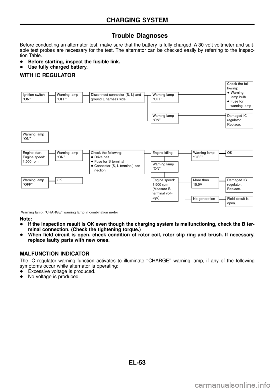
WITH IC REGULATOR
Check the fol-
lowing:
+Warning
lamp bulb
+Fuse for
warning lamp
Ignition switch
``ON''Warning lamp
``OFF''Disconnect connector (S, L) and
ground L harness side.Warning lamp
``OFF''
Warning lamp
``ON''Damaged IC
regulator.
Replace.
Warning lamp
``ON''
Engine start.
Engine speed:
1,500 rpmWarning lamp
``ON''Check the following:
+Drive belt
+Fuse for S terminal
+Connector (S, L terminal) con-
nectionEngine idlingWarning lamp
``OFF''OK
Warning lamp
``ON''
Warning lamp
``OFF''OKEngine speed:
1,500 rpm
(Measure B
terminal volt-
age)More than
15.5VDamaged IC
regulator.
Replace.
No generationField circuit is
open.
Warning lamp: ``CHARGE'' warning lamp in combination meter
Note:
+If the inspection result is OK even though the charging system is malfunctioning, check the B ter-
minal connection. (Check the tightening torque.)
+When ®eld circuit is open, check condition of rotor coil, rotor slip ring and brush. If necessary,
replace faulty parts with new ones.
MALFUNCTION INDICATOR
The IC regulator warning function activates to illuminate ``CHARGE'' warning lamp, if any of the following
symptoms occur while alternator is operating:
+Excessive voltage is produced.
+No voltage is produced.
CHARGING SYSTEM
EL-53
Page 67 of 326
Bulb Replacement
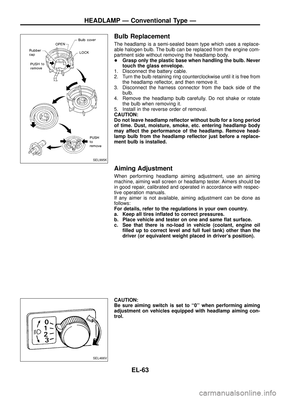
The headlamp is a semi-sealed beam type which uses a replace-
able halogen bulb. The bulb can be replaced from the engine com-
partment side without removing the headlamp body.
+Grasp only the plastic base when handling the bulb. Never
touch the glass envelope.
1. Disconnect the battery cable.
2. Turn the bulb retaining ring counterclockwise until it is free from
the headlamp re¯ector, and then remove it.
3. Disconnect the harness connector from the back side of the
bulb.
4. Remove the headlamp bulb carefully. Do not shake or rotate
the bulb when removing it.
5. Install in the reverse order of removal.
CAUTION:
Do not leave headlamp re¯ector without bulb for a long period
of time. Dust, moisture, smoke, etc. entering headlamp body
may affect the performance of the headlamp. Remove head-
lamp bulb from the headlamp re¯ector just before a replace-
ment bulb is installed.
Aiming Adjustment
When performing headlamp aiming adjustment, use an aiming
machine, aiming wall screen or headlamp tester. Aimers should be
in good repair, calibrated and operated in accordance with respec-
tive operation manuals.
If any aimer is not available, aiming adjustment can be done as
follows:
For details, refer to the regulations in your own country.
a. Keep all tires in¯ated to correct pressures.
b. Place vehicle and tester on one and same ¯at surface.
c. See that there is no-load in vehicle (coolant, engine oil
®lled up to correct level and full fuel tank) other than the
driver (or equivalent weight placed in driver's position).
CAUTION:
Be sure aiming switch is set to ``0'' when performing aiming
adjustment on vehicles equipped with headlamp aiming con-
trol.
SEL995K
SEL466V
HEADLAMP Ð Conventional Type Ð
EL-63
Page 115 of 326
SYMPTOM CHART
Symptom chart 1 (Malfunction is indicated in Diagnosis mode)
Symptom Possible causes Repair order
Speedometer and/or odo/trip
meter indicate(s) malfunction
in Diagnosis mode.+Speedometer (Uni®ed meter control unit)+Replace speedometer (uni®ed meter control unit).
Multiple meter/gauge indicate
malfunction in Diagnosis
mode.
One of tachometer/fuel gauge/
water temp. gauge indicates
malfunction in Diagnosis
mode.+Meter/Gauge
+Speedometer (Uni®ed meter control unit)1. Check resistance of meter/gauge indicating malfunction. If
the resistance is NG, replace the meter/gauge. Refer to
``METER/GAUGE RESISTANCE CHECK'', EL-114.
2. If the resistance is OK, replace speedometer (uni®ed meter
control unit).
Symptom chart 2 (No malfunction is indicated in Diagnosis mode)
Symptom Possible causes Repair order
Speedometer and odo/trip
meter are malfunctioning.1. Sensor
- Speedometer, Odo/Trip meter
2. FPC connector
3. Speedometer (Uni®ed meter control unit)1. Check vehicle speed sensor.
INSPECTION/VEHICLE SPEED SENSOR (Refer to EL-112.)
2. Check FPC connector. Refer to ``Flexible Print Circuit
(FPC)'', EL-109.
3. Replace speedometer (uni®ed meter control unit).
Multiple meter/gauge are mal-
functioning. (except
speedometer, odo/trip meter)1. FPC connector
2. Speedometer (Uni®ed meter control unit)1. Check FPC connector. Refer to ``Flexible Print Circuit
(FPC)'', EL-109.
2. Replace speedometer (uni®ed meter control unit).
One of tachometer/fuel gauge/
water temp. gauge is malfunc-
tioning.1. Sensor/Engine revolution signal
- Tachometer
- Fuel gauge
- Water temp. gauge
2. FPC connector
3. Speedometer (Uni®ed meter control unit)1. Check the sensor for malfunctioning meter/gauge.
INSPECTION/ENGINE REVOLUTION SIGNAL (Refer to
EL-113.)
INSPECTION/FUEL TANK GAUGE (Refer to EL-113.)
INSPECTION/THERMAL TRANSMITTER (Refer to EL-114.)
2. Check FPC connector. Refer to ``Flexible Print Circuit
(FPC)'', EL-109.
3. Replace speedometer (uni®ed meter control unit).
Before starting trouble diagnoses above, perform PRELIMINARY CHECK, EL-110.
POWER SUPPLY AND GROUND CIRCUIT CHECK
Power supply circuit check
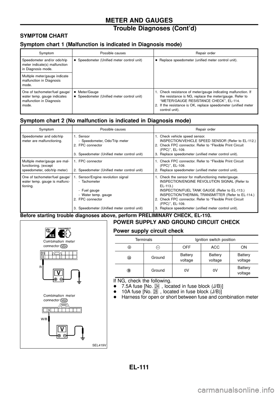
Terminals Ignition switch position
Å@OFF ACC ON
j
33GroundBattery
voltageBattery
voltageBattery
voltage
j
9Ground 0V 0VBattery
voltage
If NG, check the following.
+7.5A fuse [No.
24, located in fuse block (J/B)]
+10A fuse [No.
28, located in fuse block (J/B)]
+Harness for open or short between fuse and combination meter
SEL419V
METER AND GAUGES
Trouble Diagnoses (Cont'd)
EL-111
Page 117 of 326
INSPECTION/ENGINE REVOLUTION SIGNAL
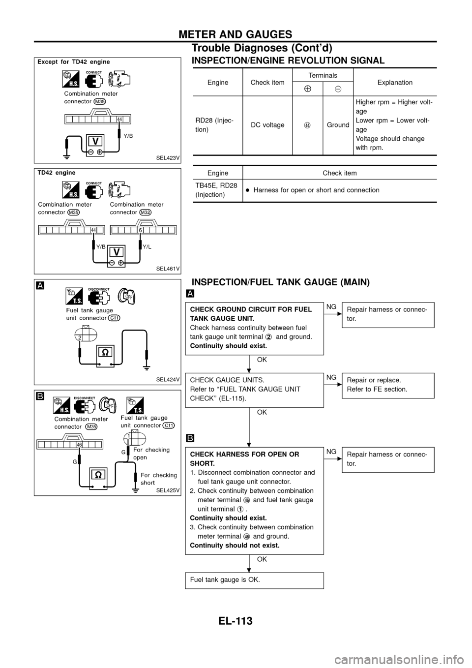
Engine Check itemTerminals
ExplanationÅ@
RD28 (Injec-
tion)DC voltagej
44GroundHigher rpm = Higher volt-
age
Lower rpm = Lower volt-
age
Voltage should change
with rpm.
Engine Check item
TB45E, RD28
(Injection)+Harness for open or short and connection
INSPECTION/FUEL TANK GAUGE (MAIN)
CHECK GROUND CIRCUIT FOR FUEL
TANK GAUGE UNIT.
Check harness continuity between fuel
tank gauge unit terminalj
2and ground.
Continuity should exist.
OK
cNG
Repair harness or connec-
tor.
CHECK GAUGE UNITS.
Refer to ``FUEL TANK GAUGE UNIT
CHECK'' (EL-115).
OK
cNG
Repair or replace.
Refer to FE section.
CHECK HARNESS FOR OPEN OR
SHORT.
1. Disconnect combination connector and
fuel tank gauge unit connector.
2. Check continuity between combination
meter terminalj
46and fuel tank gauge
unit terminalj
1.
Continuity should exist.
3. Check continuity between combination
meter terminalj
46and ground.
Continuity should not exist.
OK
cNG
Repair harness or connec-
tor.
Fuel tank gauge is OK.
SEL423V
SEL461V
SEL424V
SEL425V
.
.
.
METER AND GAUGES
Trouble Diagnoses (Cont'd)
EL-113
Page 122 of 326
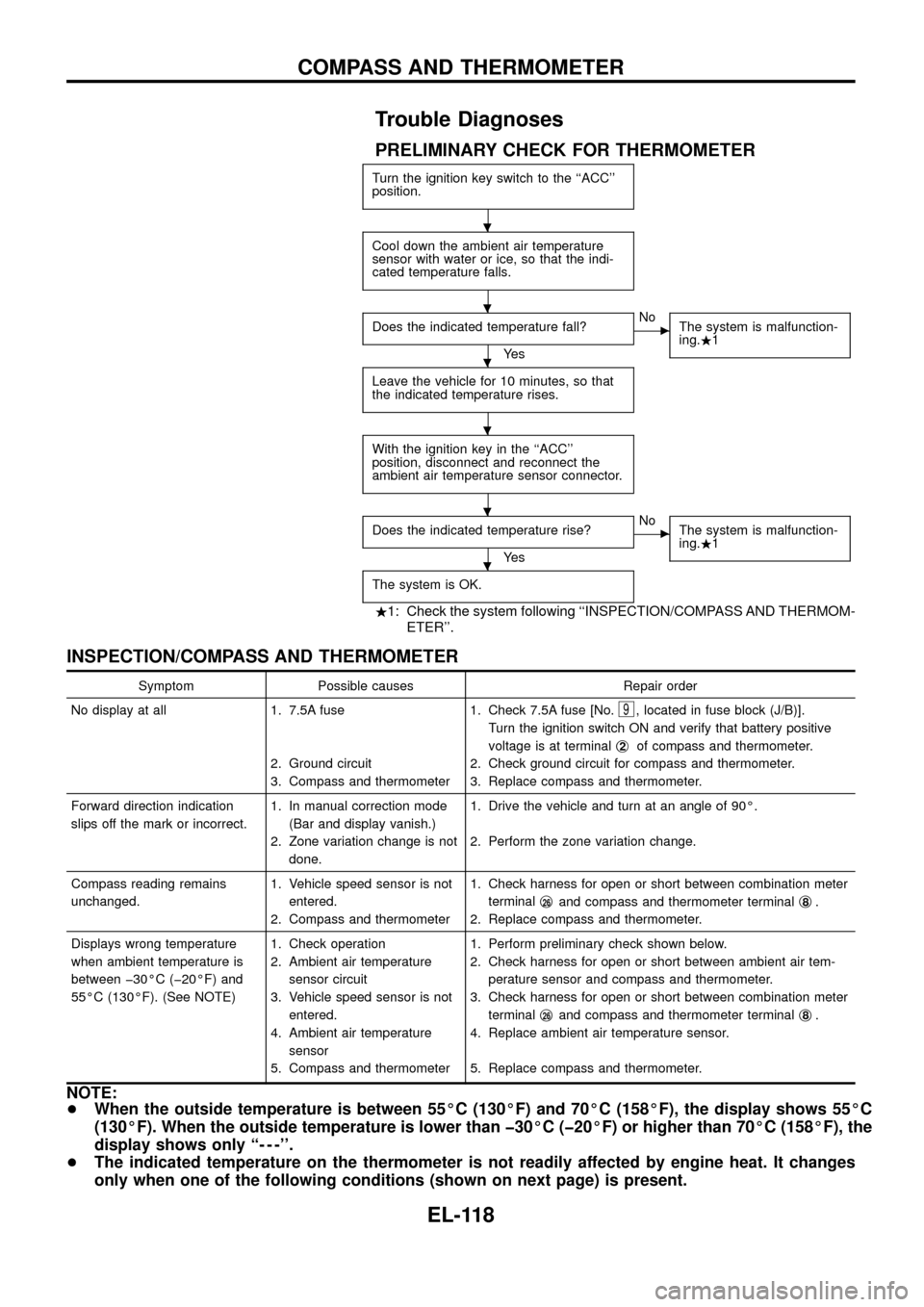
Trouble Diagnoses
PRELIMINARY CHECK FOR THERMOMETER
Turn the ignition key switch to the ``ACC''
position.
Cool down the ambient air temperature
sensor with water or ice, so that the indi-
cated temperature falls.
Does the indicated temperature fall?
Ye s
cNo
The system is malfunction-
ing..1
Leave the vehicle for 10 minutes, so that
the indicated temperature rises.
With the ignition key in the ``ACC''
position, disconnect and reconnect the
ambient air temperature sensor connector.
Does the indicated temperature rise?
Ye s
cNo
The system is malfunction-
ing..1
The system is OK.
.1: Check the system following ``INSPECTION/COMPASS AND THERMOM-
ETER''.
INSPECTION/COMPASS AND THERMOMETER
Symptom Possible causes Repair order
No display at all 1. 7.5A fuse
2. Ground circuit
3. Compass and thermometer1. Check 7.5A fuse [No.
9, located in fuse block (J/B)].
Turn the ignition switch ON and verify that battery positive
voltage is at terminalj
2of compass and thermometer.
2. Check ground circuit for compass and thermometer.
3. Replace compass and thermometer.
Forward direction indication
slips off the mark or incorrect.1. In manual correction mode
(Bar and display vanish.)
2. Zone variation change is not
done.1. Drive the vehicle and turn at an angle of 90É.
2. Perform the zone variation change.
Compass reading remains
unchanged.1. Vehicle speed sensor is not
entered.
2. Compass and thermometer1. Check harness for open or short between combination meter
terminalj
26and compass and thermometer terminalj8.
2. Replace compass and thermometer.
Displays wrong temperature
when ambient temperature is
between þ30ÉC (þ20ÉF) and
55ÉC (130ÉF). (See NOTE)1. Check operation
2. Ambient air temperature
sensor circuit
3. Vehicle speed sensor is not
entered.
4. Ambient air temperature
sensor
5. Compass and thermometer1. Perform preliminary check shown below.
2. Check harness for open or short between ambient air tem-
perature sensor and compass and thermometer.
3. Check harness for open or short between combination meter
terminalj
26and compass and thermometer terminalj8.
4. Replace ambient air temperature sensor.
5. Replace compass and thermometer.
NOTE:
+When the outside temperature is between 55ÉC (130ÉF) and 70ÉC (158ÉF), the display shows 55ÉC
(130ÉF). When the outside temperature is lower than þ30ÉC (þ20ÉF) or higher than 70ÉC (158ÉF), the
display shows only ``- - -''.
+The indicated temperature on the thermometer is not readily affected by engine heat. It changes
only when one of the following conditions (shown on next page) is present.
.
.
.
.
.
.
COMPASS AND THERMOMETER
EL-118
Page 176 of 326
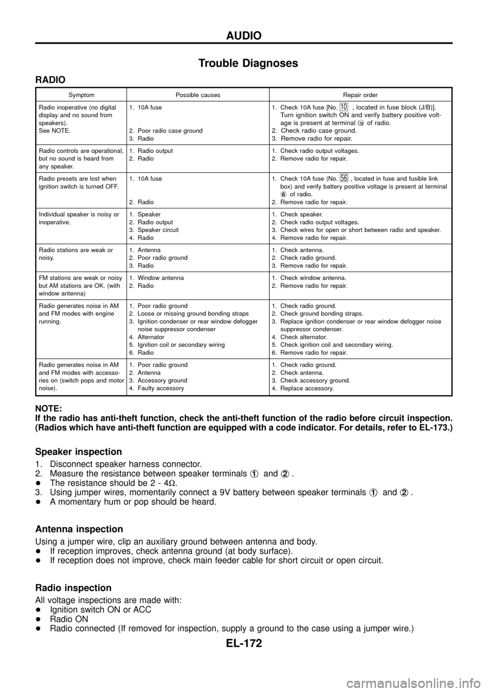
Trouble Diagnoses
RADIO
Symptom Possible causes Repair order
Radio inoperative (no digital
display and no sound from
speakers).
See NOTE.1. 10A fuse
2. Poor radio case ground
3. Radio1. Check 10A fuse [No.
10, located in fuse block (J/B)].
Turn ignition switch ON and verify battery positive volt-
age is present at terminalj
10of radio.
2. Check radio case ground.
3. Remove radio for repair.
Radio controls are operational,
but no sound is heard from
any speaker.1. Radio output
2. Radio1. Check radio output voltages.
2. Remove radio for repair.
Radio presets are lost when
ignition switch is turned OFF.1. 10A fuse
2. Radio1. Check 10A fuse (No.
56, located in fuse and fusible link
box) and verify battery positive voltage is present at terminal
j
6of radio.
2. Remove radio for repair.
Individual speaker is noisy or
inoperative.1. Speaker
2. Radio output
3. Speaker circuit
4. Radio1. Check speaker.
2. Check radio output voltages.
3. Check wires for open or short between radio and speaker.
4. Remove radio for repair.
Radio stations are weak or
noisy.1. Antenna
2. Poor radio ground
3. Radio1. Check antenna.
2. Check radio ground.
3. Remove radio for repair.
FM stations are weak or noisy
but AM stations are OK. (with
window antenna)1. Window antenna
2. Radio1. Check window antenna.
2. Remove radio for repair.
Radio generates noise in AM
and FM modes with engine
running.1. Poor radio ground
2. Loose or missing ground bonding straps
3. Ignition condenser or rear window defogger
noise suppressor condenser
4. Alternator
5. Ignition coil or secondary wiring
6. Radio1. Check radio ground.
2. Check ground bonding straps.
3. Replace ignition condenser or rear window defogger noise
suppressor condenser.
4. Check alternator.
5. Check ignition coil and secondary wiring.
6. Remove radio for repair.
Radio generates noise in AM
and FM modes with accesso-
ries on (switch pops and motor
noise).1. Poor radio ground
2. Antenna
3. Accessory ground
4. Faulty accessory1. Check radio ground.
2. Check antenna.
3. Check accessory ground.
4. Replace accessory.
NOTE:
If the radio has anti-theft function, check the anti-theft function of the radio before circuit inspection.
(Radios which have anti-theft function are equipped with a code indicator. For details, refer to EL-173.)
Speaker inspection
1. Disconnect speaker harness connector.
2. Measure the resistance between speaker terminalsj
1andj2.
+The resistance should be2-4W.
3. Using jumper wires, momentarily connect a 9V battery between speaker terminalsj
1andj2.
+A momentary hum or pop should be heard.
Antenna inspection
Using a jumper wire, clip an auxiliary ground between antenna and body.
+If reception improves, check antenna ground (at body surface).
+If reception does not improve, check main feeder cable for short circuit or open circuit.
Radio inspection
All voltage inspections are made with:
+Ignition switch ON or ACC
+Radio ON
+Radio connected (If removed for inspection, supply a ground to the case using a jumper wire.)
AUDIO
EL-172
Page 235 of 326
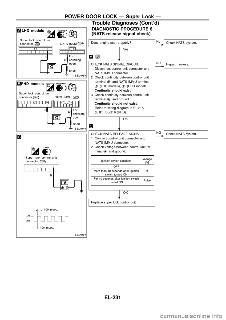
DIAGNOSTIC PROCEDURE 6
(NATS release signal check)
Does engine start properly?
Ye s
cNo
Check NATS system.
CHECK NATS SIGNAL CIRCUIT.
1. Disconnect control unit connector and
NATS IMMU connector.
2. Check continuity between control unit
terminalj
9and NATS IMMU terminal
j
3(LHD models),j7(RHD models).
Continuity should exist.
3. Check continuity between control unit
terminalj
9and ground.
Continuity should not exist.
Refer to wiring diagram in EL-215
(LHD), EL-219 (RHD).
OK
cNG
Repair harness.
CHECK NATS RELEASE SIGNAL.
1. Connect control unit connector and
NATS IMMU connector.
2. Check voltage between control unit ter-
minalj
9and ground.
OK
cNG
Check NATS system.
Replace super lock control unit.
Ignition switch conditionVoltage
[V]
OFF
5
More than 10 seconds after ignition
switch turned ON
For 10 seconds after ignition switch
turned ONPulse
SEL493V
SEL494V
SEL495V
.
.
.
POWER DOOR LOCK Ð Super Lock Ð
Trouble Diagnoses (Cont'd)
EL-231
Page 251 of 326
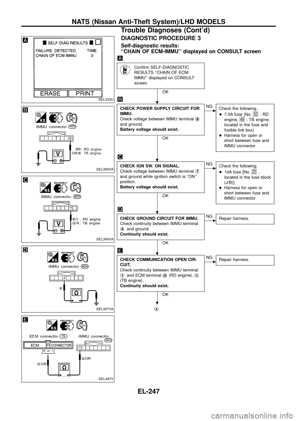
DIAGNOSTIC PROCEDURE 3
Self-diagnostic results:
``CHAIN OF ECM-IMMU'' displayed on CONSULT screen
Con®rm SELF-DIAGNOSTIC
RESULTS ``CHAIN OF ECM-
IMMU'' displayed on CONSULT
screen.
OK
CHECK POWER SUPPLY CIRCUIT FOR
IMMU.
Check voltage between IMMU terminalj
8
and ground.
Battery voltage should exist.
OK
cNG
Check the following.
+7.5A fuse (No.
50:RD
engine,
49: TB engine,
located in the fuse and
fusible link box)
+Harness for open or
short between fuse and
IMMU connector
CHECK IGN SW. ON SIGNAL.
Check voltage between IMMU terminalj
7
and ground while ignition switch is ``ON''
position.
Battery voltage should exist.
OK
cNG
Check the following.
+10A fuse [No.
25,
located in the fuse block
(J/B)]
+Harness for open or
short between fuse and
IMMU connector
CHECK GROUND CIRCUIT FOR IMMU.
Check continuity between IMMU terminal
j
4and ground.
Continuity should exist.
OK
cNG
Repair harness.
CHECK COMMUNICATION OPEN CIR-
CUIT.
Check continuity between IMMU terminal
j
1and ECM terminalj55(RD engine),j11
(TB engine).
Continuity should exist.
OK
cNG
Repair harness.
jA
SEL333U
SEL395VA
SEL396VA
SEL397VA
SEL497V
.
.
.
.
.
NATS (Nissan Anti-Theft System)/LHD MODELS
Trouble Diagnoses (Cont'd)
EL-247
Page 269 of 326
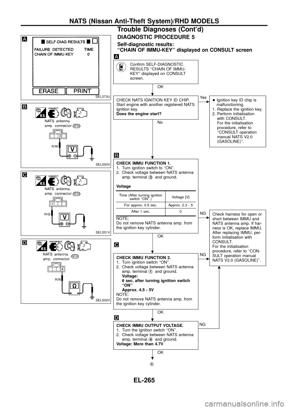
DIAGNOSTIC PROCEDURE 5
Self-diagnostic results:
``CHAIN OF IMMU-KEY'' displayed on CONSULT screen
Con®rm SELF-DIAGNOSTIC
RESULTS ``CHAIN OF IMMU-
KEY'' displayed on CONSULT
screen.
OK
CHECK NATS IGNITION KEY ID CHIP.
Start engine with another registered NATS
ignition key.
Does the engine start?
No
cYe s
+Ignition key ID chip is
malfunctioning.
1. Replace the ignition key.
2. Perform initialisation
with CONSULT.
For the initialisation
procedure, refer to
``CONSULT operation
manual NATS V2.0
(GASOLINE)''.
CHECK IMMU FUNCTION 1.
1. Turn ignition switch to ``ON''.
2. Check voltage between NATS antenna
amp. terminalj
3and ground.
Voltage
NOTE:
Do not remove NATS antenna amp. from
the ignition key cylinder.
OK
cNG
Check harness for open or
short between IMMU and
NATS antenna amp. If har-
ness is OK, replace IMMU.
After replacing IMMU, per-
form initialisation with
CONSULT.
For the initialisation
procedure, refer to ``CON-
SULT operation manual
NATS V2.0 (GASOLINE)''.
CHECK IMMU FUNCTION 2.
1. Turn ignition switch ``ON''.
2. Check voltage between NATS antenna
amp. terminalj
1and ground.
Voltage:
6 sec. after turning ignition switch
``ON''
Approx. 4.5 - 5V
NOTE:
Do not remove NATS antenna amp. from
the ignition key cylinder.
OK
cNG
CHECK IMMU OUTPUT VOLTAGE.
1. Turn the ignition switch ``ON''.
2. Check voltage between NATS antenna
amp. terminalj
4and ground.
Voltage: More than 4.7V
OK
m
NG
j
A
Time (After turning ignition
switch ``ON''.)Voltage [V]
For approx. 0.5 sec. Approx. 2.3 - 5
After 1 sec. 0
SEL373U
SEL550V
SEL551V
SEL502V
.
.
.
.
.
NATS (Nissan Anti-Theft System)/RHD MODELS
Trouble Diagnoses (Cont'd)
EL-265
Page 271 of 326
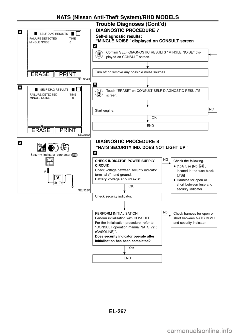
DIAGNOSTIC PROCEDURE 7
Self-diagnostic results:
``MINGLE NOISE'' displayed on CONSULT screen
Con®rm SELF-DIAGNOSTIC RESULTS ``MINGLE NOISE'' dis-
played on CONSULT screen.b
Turn off or remove any possible noise sources.
Touch ``ERASE'' on CONSULT SELF-DIAGNOSTIC RESULTS
screen.
Start engine.
OKNG
END
DIAGNOSTIC PROCEDURE 8
``NATS SECURITY IND. DOES NOT LIGHT UP''
CHECK INDICATOR POWER SUPPLY
CIRCUIT.
Check voltage between security indicator
terminalj
1and ground.
Battery voltage should exist.
OK
cNG
Check the following.
+7.5A fuse [No.
24,
located in the fuse block
(J/B)]
+Harness for open or
short between fuse and
security indicator
Check security indicator.
PERFORM INITIALISATION.
Perform initialisation with CONSULT.
For the initialisation procedure, refer to
``CONSULT operation manual NATS V2.0
(GASOLINE)''.
Does security indicator operate after
initialisation has been completed?
Ye s
cNo
Check harness for open or
short between NATS IMMU
and security indicator.
END
SEL384U
SEL385U
SEL552V
.
.
.
.
.
.
.
NATS (Nissan Anti-Theft System)/RHD MODELS
Trouble Diagnoses (Cont'd)
EL-267