NISSAN PATROL 1998 Y61 / 5.G Electrical System Owner's Manual
PATROL 1998 Y61 / 5.G
NISSAN
NISSAN
https://www.carmanualsonline.info/img/5/616/w960_616-0.png
NISSAN PATROL 1998 Y61 / 5.G Electrical System Owner's Manual
Page 152 of 326
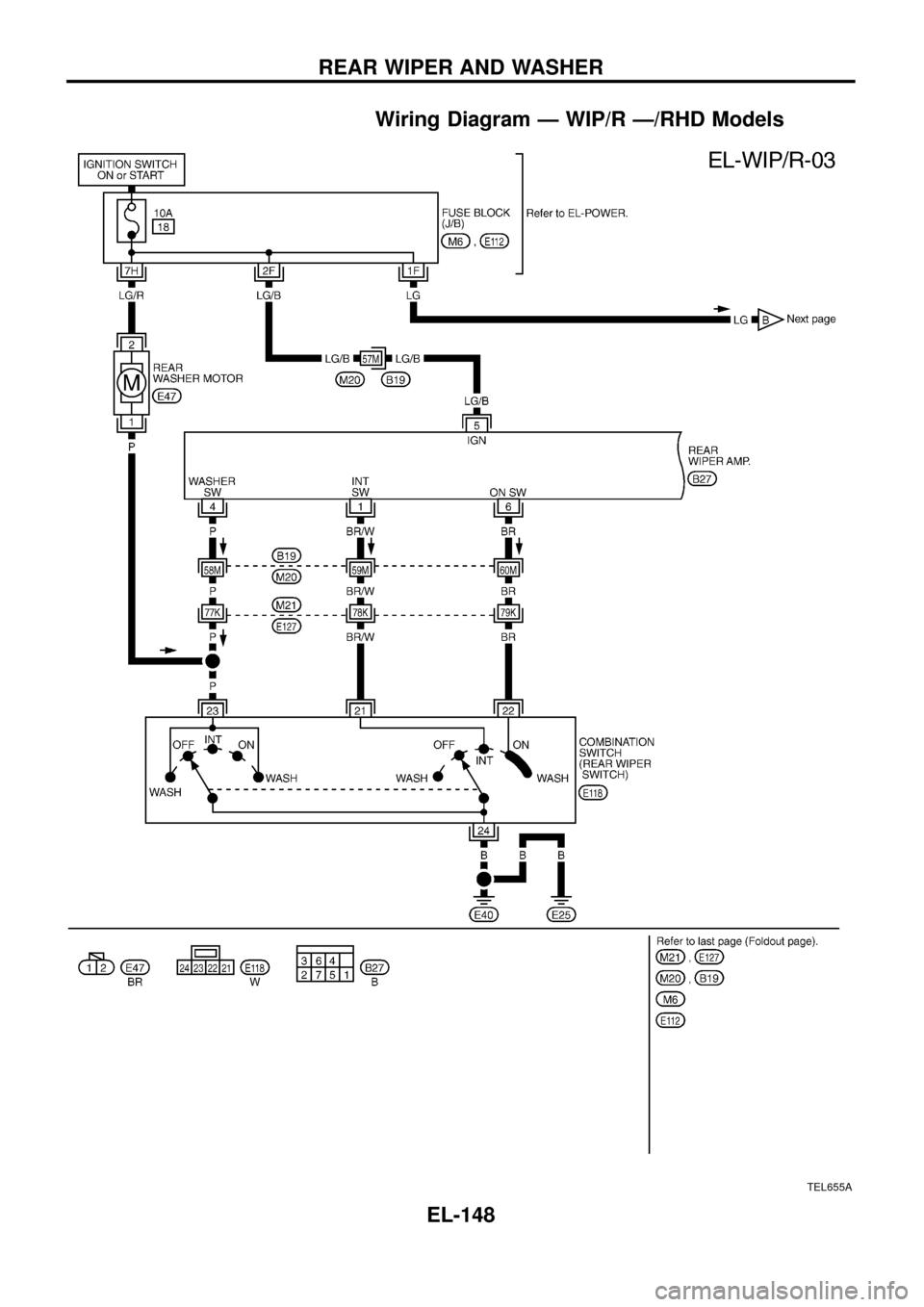
Wiring Diagram Ð WIP/R Ð/RHD Models
TEL655A
REAR WIPER AND WASHER
EL-148
Page 153 of 326
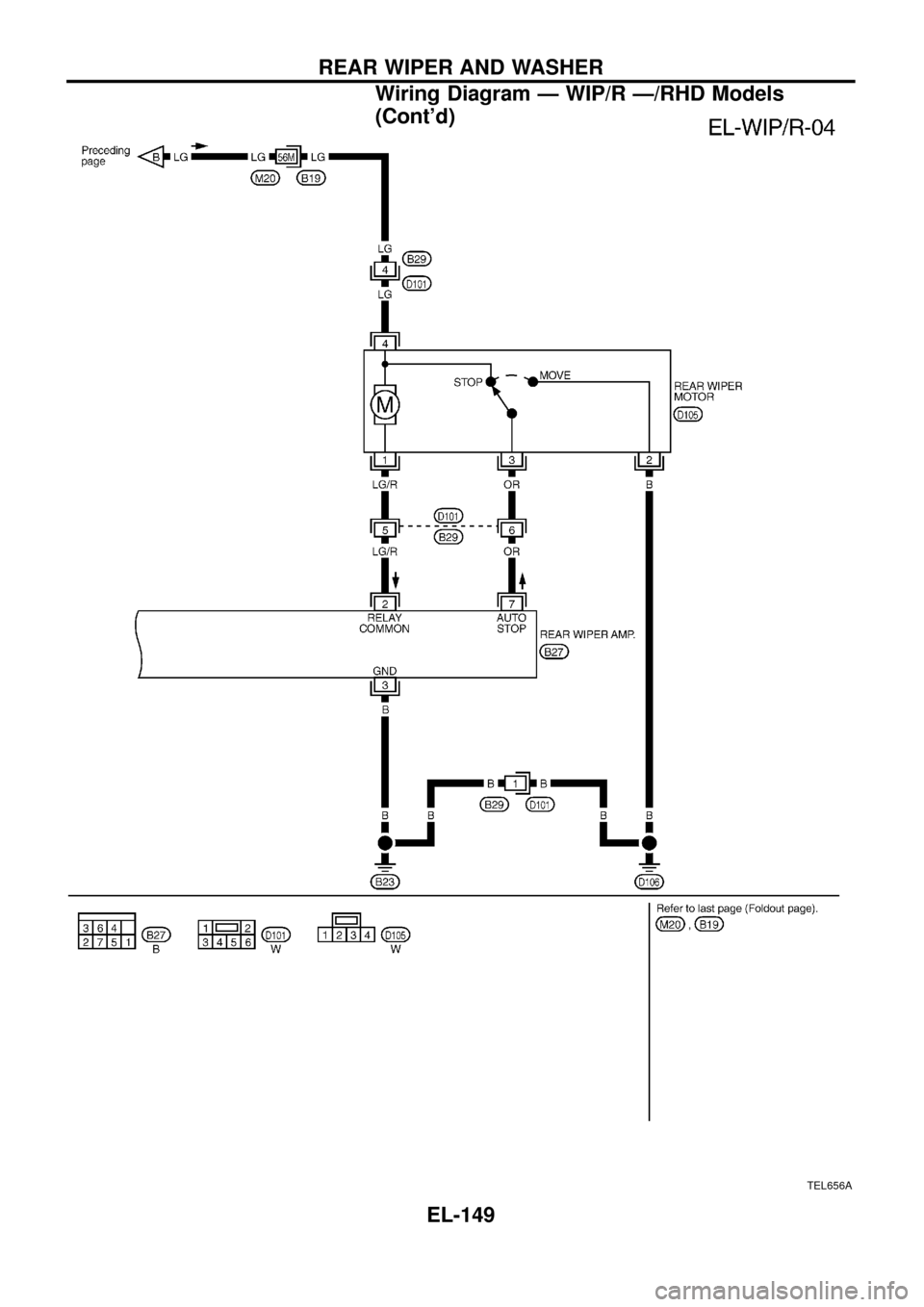
TEL656A
REAR WIPER AND WASHER
Wiring Diagram Ð WIP/R Ð/RHD Models
(Cont'd)
EL-149
Page 154 of 326
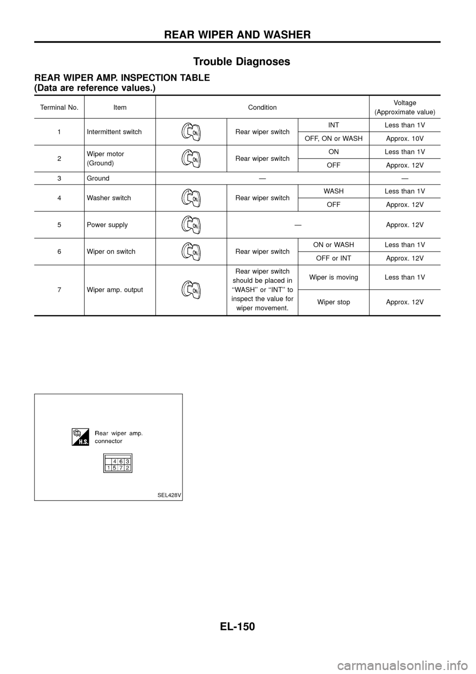
Trouble Diagnoses
REAR WIPER AMP. INSPECTION TABLE
(Data are reference values.)
Terminal No. Item ConditionVoltage
(Approximate value)
1 Intermittent switch
Rear wiper switchINT Less than 1V
OFF, ON or WASH Approx. 10V
2Wiper motor
(Ground)
Rear wiper switchON Less than 1V
OFF Approx. 12V
3 Ground Ð Ð
4 Washer switch
Rear wiper switchWASH Less than 1V
OFF Approx. 12V
5 Power supply
Ð Approx. 12V
6 Wiper on switch
Rear wiper switchON or WASH Less than 1V
OFF or INT Approx. 12V
7 Wiper amp. output
Rear wiper switch
should be placed in
``WASH'' or ``INT'' to
inspect the value for
wiper movement.Wiper is moving Less than 1V
Wiper stop Approx. 12V
SEL428V
REAR WIPER AND WASHER
EL-150
Page 155 of 326
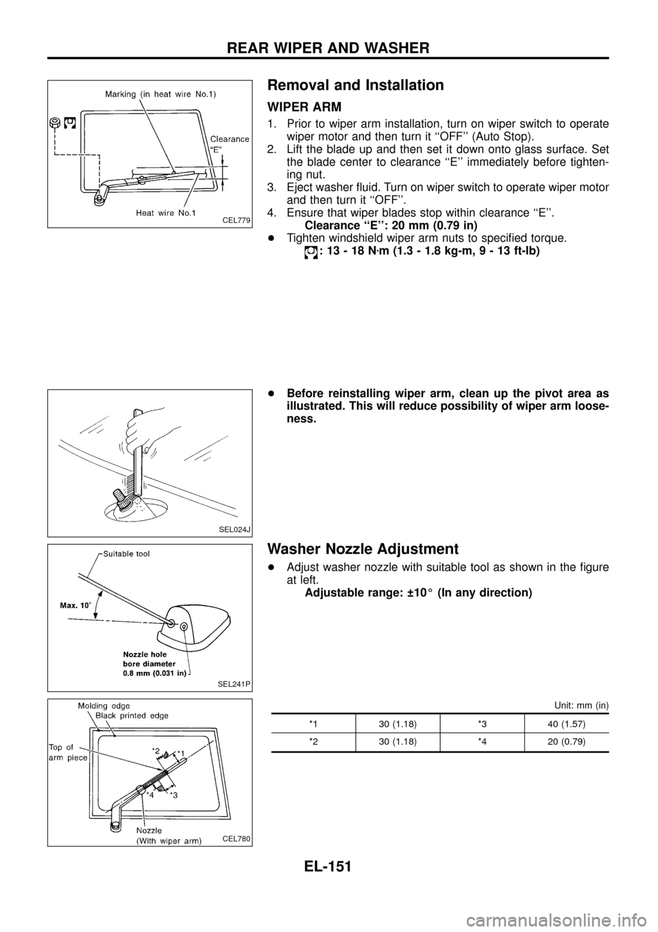
Removal and Installation
WIPER ARM
1. Prior to wiper arm installation, turn on wiper switch to operate
wiper motor and then turn it ``OFF'' (Auto Stop).
2. Lift the blade up and then set it down onto glass surface. Set
the blade center to clearance ``E'' immediately before tighten-
ing nut.
3. Eject washer ¯uid. Turn on wiper switch to operate wiper motor
and then turn it ``OFF''.
4. Ensure that wiper blades stop within clearance ``E''.
Clearance ``E'': 20 mm (0.79 in)
+Tighten windshield wiper arm nuts to speci®ed torque.
:13-18Nzm (1.3 - 1.8 kg-m,9-13ft-lb)
+Before reinstalling wiper arm, clean up the pivot area as
illustrated. This will reduce possibility of wiper arm loose-
ness.
Washer Nozzle Adjustment
+Adjust washer nozzle with suitable tool as shown in the ®gure
at left.
Adjustable range: 10É (In any direction)
Unit: mm (in)
*1 30 (1.18) *3 40 (1.57)
*2 30 (1.18) *4 20 (0.79)
CEL779
SEL024J
SEL241P
CEL780
REAR WIPER AND WASHER
EL-151
Page 156 of 326
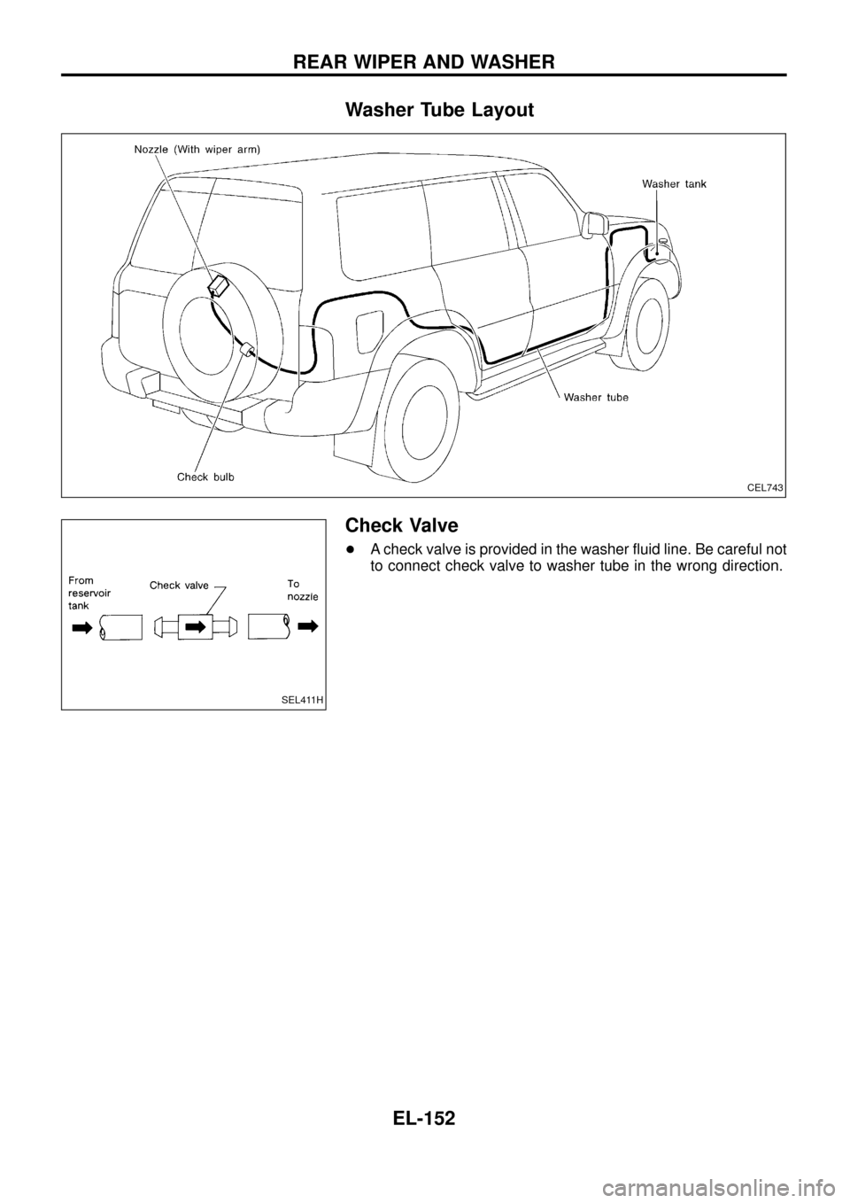
Washer Tube Layout
Check Valve
+A check valve is provided in the washer ¯uid line. Be careful not
to connect check valve to washer tube in the wrong direction.
CEL743
SEL411H
REAR WIPER AND WASHER
EL-152
Page 162 of 326
System Description
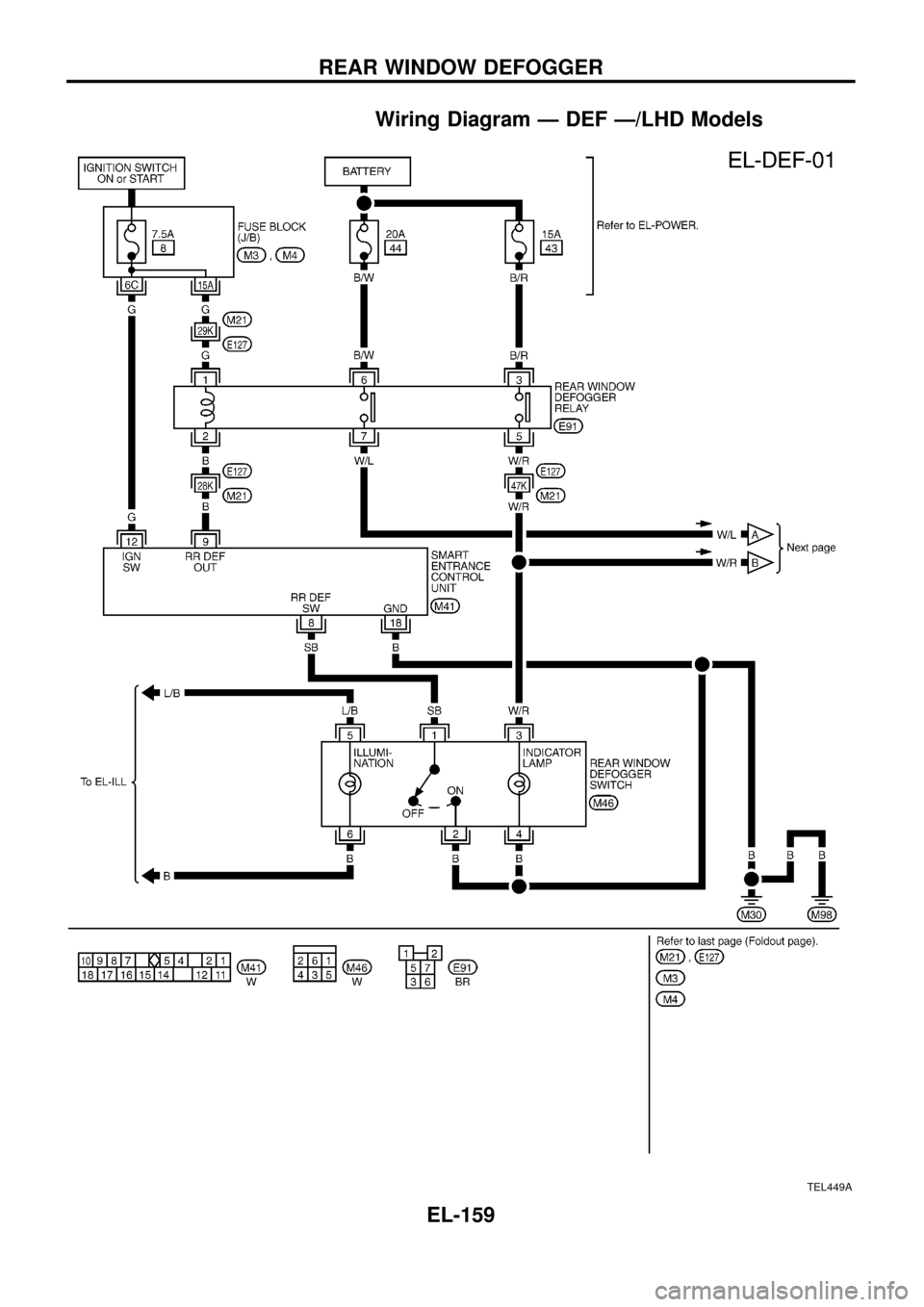
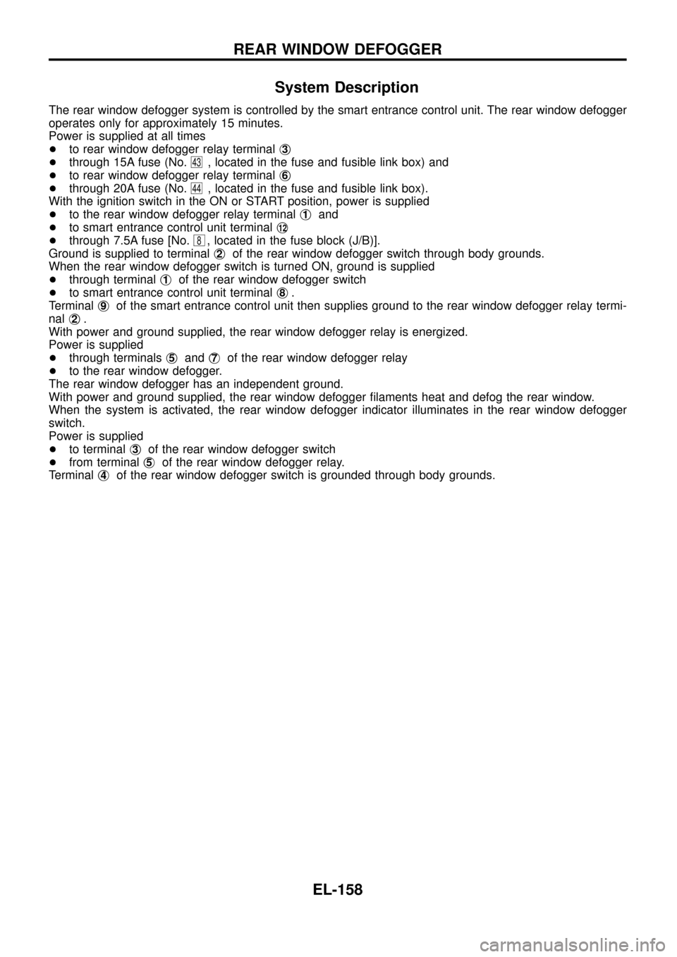
The rear window defogger system is controlled by the smart entrance control unit. The rear window defogger
operates only for approximately 15 minutes.
Power is supplied at all times
+to rear window defogger relay terminalj
3
+through 15A fuse (No.43, located in the fuse and fusible link box) and
+to rear window defogger relay terminalj
6
+through 20A fuse (No.44, located in the fuse and fusible link box).
With the ignition switch in the ON or START position, power is supplied
+to the rear window defogger relay terminalj
1and
+to smart entrance control unit terminalj
12
+through 7.5A fuse [No.8, located in the fuse block (J/B)].
Ground is supplied to terminalj
2of the rear window defogger switch through body grounds.
When the rear window defogger switch is turned ON, ground is supplied
+through terminalj
1of the rear window defogger switch
+to smart entrance control unit terminalj
8.
Terminalj
9of the smart entrance control unit then supplies ground to the rear window defogger relay termi-
nalj
2.
With power and ground supplied, the rear window defogger relay is energized.
Power is supplied
+through terminalsj
5andj7of the rear window defogger relay
+to the rear window defogger.
The rear window defogger has an independent ground.
With power and ground supplied, the rear window defogger ®laments heat and defog the rear window.
When the system is activated, the rear window defogger indicator illuminates in the rear window defogger
switch.
Power is supplied
+to terminalj
3of the rear window defogger switch
+from terminalj
5of the rear window defogger relay.
Terminalj
4of the rear window defogger switch is grounded through body grounds.
REAR WINDOW DEFOGGER
EL-158
Page 163 of 326
Wiring Diagram Ð DEF Ð/LHD Models
TEL449A
REAR WINDOW DEFOGGER
EL-159
Page 164 of 326
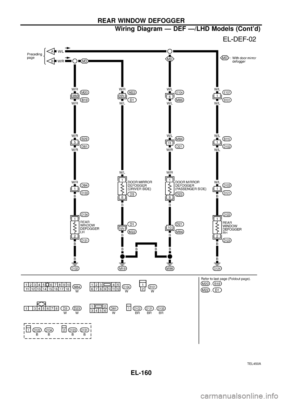
TEL450A
REAR WINDOW DEFOGGER
Wiring Diagram Ð DEF Ð/LHD Models (Cont'd)
EL-160
Page 165 of 326
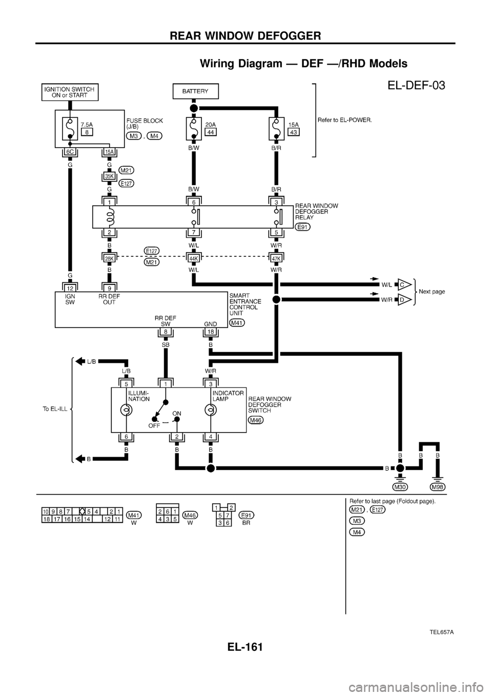
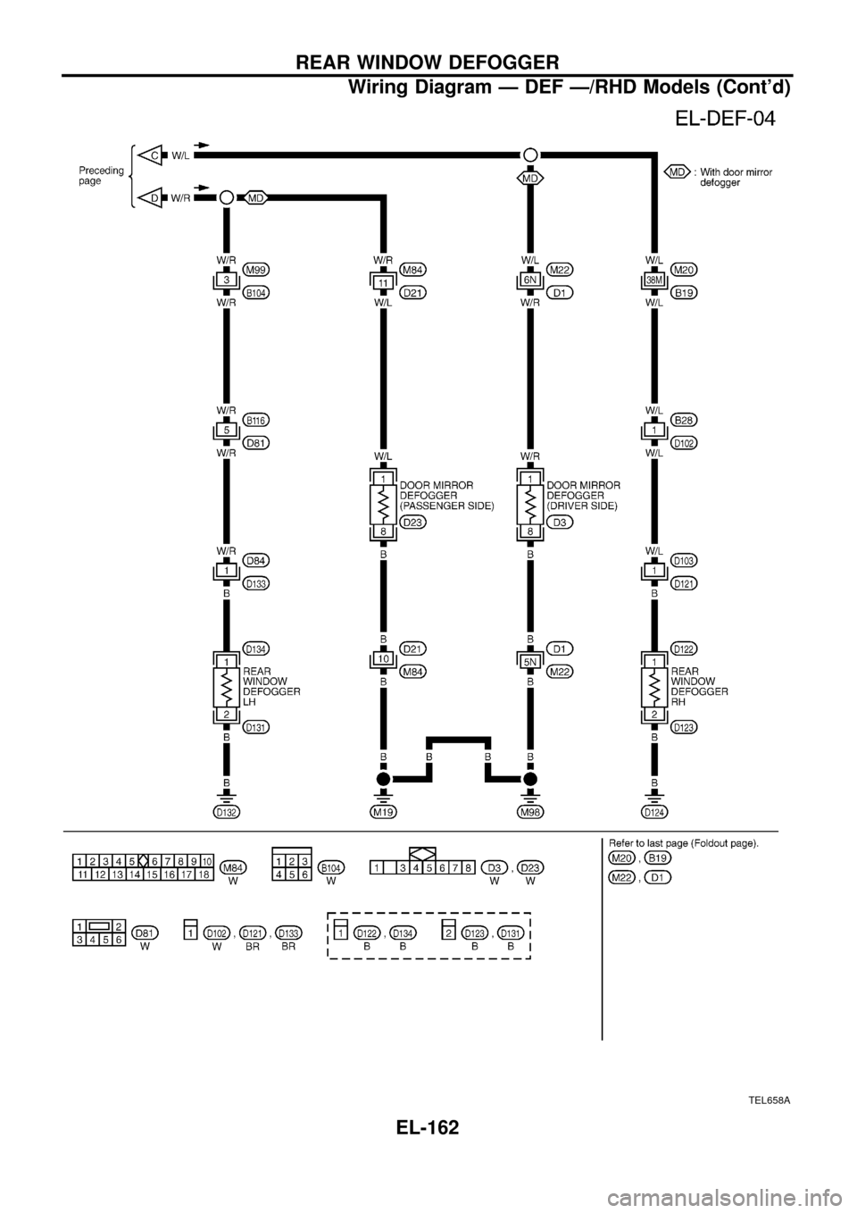
Wiring Diagram Ð DEF Ð/RHD Models
TEL657A
REAR WINDOW DEFOGGER
EL-161
Page 166 of 326
TEL658A
REAR WINDOW DEFOGGER
Wiring Diagram Ð DEF Ð/RHD Models (Cont'd)
EL-162
