door lock NISSAN PATROL 1998 Y61 / 5.G Electrical System Workshop Manual
[x] Cancel search | Manufacturer: NISSAN, Model Year: 1998, Model line: PATROL, Model: NISSAN PATROL 1998 Y61 / 5.GPages: 326, PDF Size: 11.36 MB
Page 3 of 326
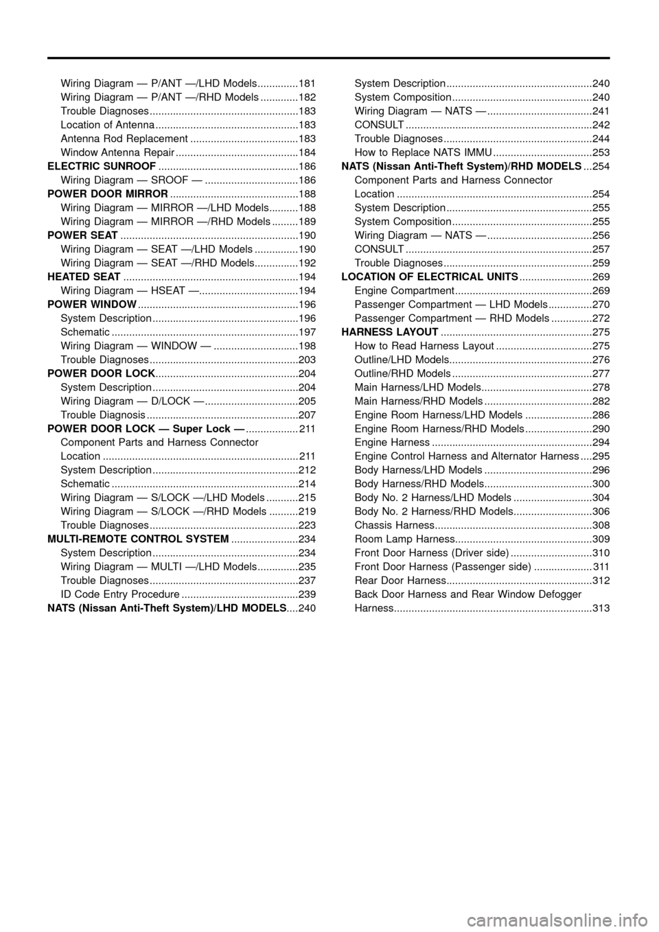
Wiring Diagram Ð P/ANT Ð/LHD Models..............181
Wiring Diagram Ð P/ANT Ð/RHD Models .............182
Trouble Diagnoses...................................................183
Location of Antenna .................................................183
Antenna Rod Replacement .....................................183
Window Antenna Repair ..........................................184
ELECTRIC SUNROOF................................................186
Wiring Diagram Ð SROOF Ð ................................186
POWER DOOR MIRROR............................................188
Wiring Diagram Ð MIRROR Ð/LHD Models..........188
Wiring Diagram Ð MIRROR Ð/RHD Models .........189
POWER SEAT.............................................................190
Wiring Diagram Ð SEAT Ð/LHD Models ...............190
Wiring Diagram Ð SEAT Ð/RHD Models...............192
HEATED SEAT............................................................194
Wiring Diagram Ð HSEAT Ð..................................194
POWER WINDOW.......................................................196
System Description ..................................................196
Schematic ................................................................197
Wiring Diagram Ð WINDOW Ð .............................198
Trouble Diagnoses...................................................203
POWER DOOR LOCK.................................................204
System Description ..................................................204
Wiring Diagram Ð D/LOCK Ð ................................205
Trouble Diagnosis ....................................................207
POWER DOOR LOCK Ð Super Lock Ð.................. 211
Component Parts and Harness Connector
Location ................................................................... 211
System Description ..................................................212
Schematic ................................................................214
Wiring Diagram Ð S/LOCK Ð/LHD Models ...........215
Wiring Diagram Ð S/LOCK Ð/RHD Models ..........219
Trouble Diagnoses...................................................223
MULTI-REMOTE CONTROL SYSTEM.......................234
System Description ..................................................234
Wiring Diagram Ð MULTI Ð/LHD Models..............235
Trouble Diagnoses...................................................237
ID Code Entry Procedure ........................................239
NATS (Nissan Anti-Theft System)/LHD MODELS....240System Description ..................................................240
System Composition ................................................240
Wiring Diagram Ð NATS Ð ....................................241
CONSULT ................................................................242
Trouble Diagnoses...................................................244
How to Replace NATS IMMU ..................................253
NATS (Nissan Anti-Theft System)/RHD MODELS...254
Component Parts and Harness Connector
Location ...................................................................254
System Description ..................................................255
System Composition ................................................255
Wiring Diagram Ð NATS Ð ....................................256
CONSULT ................................................................257
Trouble Diagnoses...................................................259
LOCATION OF ELECTRICAL UNITS.........................269
Engine Compartment ...............................................269
Passenger Compartment Ð LHD Models ...............270
Passenger Compartment Ð RHD Models ..............272
HARNESS LAYOUT....................................................275
How to Read Harness Layout .................................275
Outline/LHD Models.................................................276
Outline/RHD Models ................................................277
Main Harness/LHD Models......................................278
Main Harness/RHD Models .....................................282
Engine Room Harness/LHD Models .......................286
Engine Room Harness/RHD Models .......................290
Engine Harness .......................................................294
Engine Control Harness and Alternator Harness ....295
Body Harness/LHD Models .....................................296
Body Harness/RHD Models.....................................300
Body No. 2 Harness/LHD Models ...........................304
Body No. 2 Harness/RHD Models...........................306
Chassis Harness......................................................308
Room Lamp Harness...............................................309
Front Door Harness (Driver side) ............................310
Front Door Harness (Passenger side) .................... 311
Rear Door Harness..................................................312
Back Door Harness and Rear Window Defogger
Harness....................................................................313
Page 97 of 326
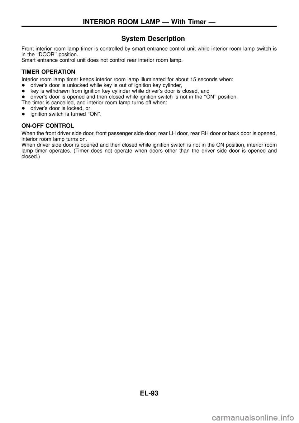
System Description
Front interior room lamp timer is controlled by smart entrance control unit while interior room lamp switch is
in the ``DOOR'' position.
Smart entrance control unit does not control rear interior room lamp.
TIMER OPERATION
Interior room lamp timer keeps interior room lamp illuminated for about 15 seconds when:
+driver's door is unlocked while key is out of ignition key cylinder,
+key is withdrawn from ignition key cylinder while driver's door is closed, and
+driver's door is opened and then closed while ignition switch is not in the ``ON'' position.
The timer is cancelled, and interior room lamp turns off when:
+driver's door is locked, or
+ignition switch is turned ``ON''.
ON-OFF CONTROL
When the front driver side door, front passenger side door, rear LH door, rear RH door or back door is opened,
interior room lamp turns on.
When driver side door is opened and then closed while ignition switch is not in the ON position, interior room
lamp timer operates. (Timer does not operate when doors other than the driver side door is opened and
closed.)
INTERIOR ROOM LAMP Ð With Timer Ð
EL-93
Page 104 of 326
Trouble Diagnoses
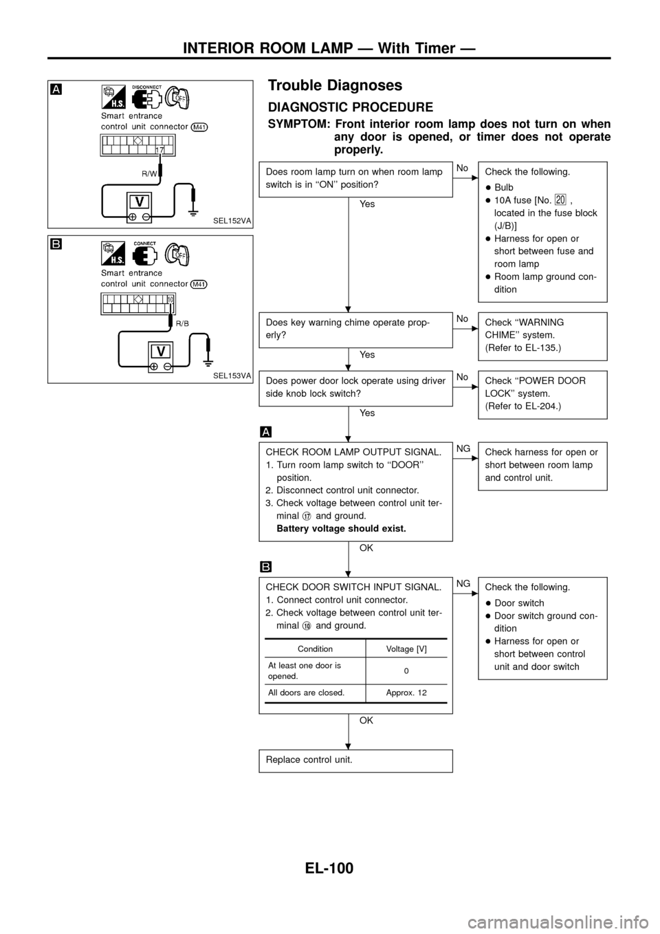
DIAGNOSTIC PROCEDURE
SYMPTOM: Front interior room lamp does not turn on when
any door is opened, or timer does not operate
properly.
Does room lamp turn on when room lamp
switch is in ``ON'' position?
Ye s
cNo
Check the following.
+Bulb
+10A fuse [No.
20,
located in the fuse block
(J/B)]
+Harness for open or
short between fuse and
room lamp
+Room lamp ground con-
dition
Does key warning chime operate prop-
erly?
Ye s
cNo
Check ``WARNING
CHIME'' system.
(Refer to EL-135.)
Does power door lock operate using driver
side knob lock switch?
Ye s
cNo
Check ``POWER DOOR
LOCK'' system.
(Refer to EL-204.)
CHECK ROOM LAMP OUTPUT SIGNAL.
1. Turn room lamp switch to ``DOOR''
position.
2. Disconnect control unit connector.
3. Check voltage between control unit ter-
minalj
17and ground.
Battery voltage should exist.
OK
cNG
Check harness for open or
short between room lamp
and control unit.
CHECK DOOR SWITCH INPUT SIGNAL.
1. Connect control unit connector.
2. Check voltage between control unit ter-
minalj
10and ground.
OK
cNG
Check the following.
+Door switch
+Door switch ground con-
dition
+Harness for open or
short between control
unit and door switch
Replace control unit.
Condition Voltage [V]
At least one door is
opened.0
All doors are closed. Approx. 12
SEL152VA
SEL153VA
.
.
.
.
.
INTERIOR ROOM LAMP Ð With Timer Ð
EL-100
Page 143 of 326
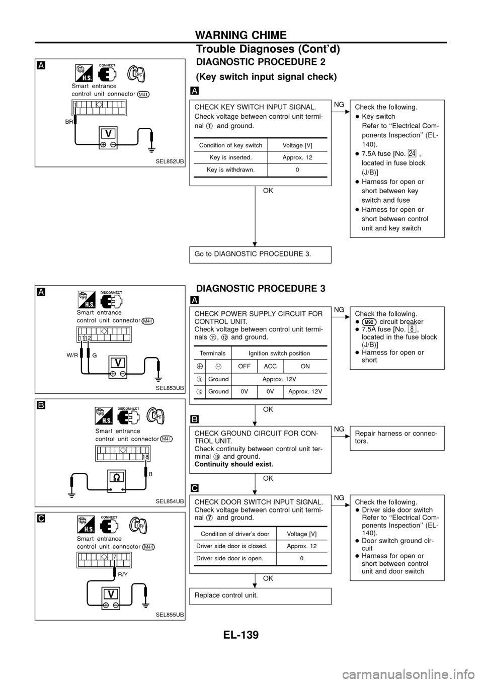
DIAGNOSTIC PROCEDURE 2
(Key switch input signal check)
CHECK KEY SWITCH INPUT SIGNAL.
Check voltage between control unit termi-
nalj
1and ground.
OK
cNG
Check the following.
+Key switch
Refer to ``Electrical Com-
ponents Inspection'' (EL-
140).
+7.5A fuse [No.
24,
located in fuse block
(J/B)]
+Harness for open or
short between key
switch and fuse
+Harness for open or
short between control
unit and key switch
Go to DIAGNOSTIC PROCEDURE 3.
Condition of key switch Voltage [V]
Key is inserted. Approx. 12
Key is withdrawn. 0
DIAGNOSTIC PROCEDURE 3
CHECK POWER SUPPLY CIRCUIT FOR
CONTROL UNIT.
Check voltage between control unit termi-
nalsj
11,j12and ground.
OK
cNG
Check the following.
+
M92circuit breaker
+7.5A fuse [No.8,
located in the fuse block
(J/B)]
+Harness for open or
short
CHECK GROUND CIRCUIT FOR CON-
TROL UNIT.
Check continuity between control unit ter-
minalj
18and ground.
Continuity should exist.
OK
cNG
Repair harness or connec-
tors.
CHECK DOOR SWITCH INPUT SIGNAL.
Check voltage between control unit termi-
nalj
7and ground.
OK
cNG
Check the following.
+Driver side door switch
Refer to ``Electrical Com-
ponents Inspection'' (EL-
140).
+Door switch ground cir-
cuit
+Harness for open or
short between control
unit and door switch
Replace control unit.
Terminals Ignition switch position
Å@OFF ACC ON
j
11Ground Approx. 12V
j
12Ground 0V 0V Approx. 12V
Condition of driver's door Voltage [V]
Driver side door is closed. Approx. 12
Driver side door is open. 0
SEL852UB
SEL853UB
SEL854UB
SEL855UB
.
.
.
.
WARNING CHIME
Trouble Diagnoses (Cont'd)
EL-139
Page 200 of 326
![NISSAN PATROL 1998 Y61 / 5.G Electrical System Workshop Manual System Description
With ignition switch in ON or START position, power is supplied
+through 7.5A fuse [No.
8, located in the fuse block (J/B)]
+to power window relay terminalj
1.
The power window rela NISSAN PATROL 1998 Y61 / 5.G Electrical System Workshop Manual System Description
With ignition switch in ON or START position, power is supplied
+through 7.5A fuse [No.
8, located in the fuse block (J/B)]
+to power window relay terminalj
1.
The power window rela](/img/5/616/w960_616-199.png)
System Description
With ignition switch in ON or START position, power is supplied
+through 7.5A fuse [No.
8, located in the fuse block (J/B)]
+to power window relay terminalj
1.
The power window relay is energized and power is supplied
+through power window relay terminalj
5
+to power window main switch terminalj1,
+to power window sub switch terminalj
5.
MANUAL OPERATION
NOTE:
Numbers in parentheses are terminal numbers, when power window switch is pressed in the UP and DOWN
positions respectively.
Driver side
When the driver side switch in the power window main switch is pressed in the up position, power is supplied
+to driver side power window regulator terminal (j
2,j1)
+through power window main switch terminal (j
9,j8).
Ground is supplied
+to driver side power window regulator terminal (j
1,j2)
+through power window main switch terminal (j
8,j9).
Then, the motor raises or lowers the window until the switch is released.
Passenger side
MAIN SWITCH OPERATION
Power is supplied
+through power window main switch (j
5,j6)
+to front power window sub-switch (j
3,j4).
The subsequent operation is the same as the sub-switch operation.
SUB-SWITCH OPERATION
Power is supplied
+through front power window sub-switch (j
1,j2)
+to passenger side power window regulator (j
2,j1).
Ground is supplied
+to passenger side power window regulator (j
1,j2)
+through front power window sub-switch (j
2,j1)
+to front power window sub-switch (j
4,j3)
+through power window main switch (j
6,j5).
Then, the motor raises or lowers the window until the switch is released.
Rear door
Rear door windows will raise and lower in the same manner as passenger side door window.
AUTO OPERATION
The power window AUTO feature enables the driver to open or close the driver's window without holding the
window switch in the respective position.
When the AUTO switch in the main switch is pressed and released, the driver's window will travel to the fully
open or closed position.
POWER WINDOW LOCK
The power window lock is designed to lock operation of all windows except for driver's door window.
When the lock switch is pressed to lock position, ground of the sub-switches in the power window main switch
is disconnected. This prevents the power window motors from operating.
POWER WINDOW
EL-196
Page 208 of 326
System Description
Power is supplied at all times
+through 40A fusible link (Letter
e, located in the fuse and fusible link box)
+to circuit breaker terminalj
1
+through circuit breaker terminalj2
+to smart entrance control unit terminalj11.
Ground is supplied to smart entrance control unit terminalj
18through body grounds.
INPUT
When the door lock & unlock switch (power window main switch) is in LOCKED position, ground signal is
supplied
+to smart entrance control unit terminalj
4
+through door lock & unlock switch terminalj14.
When the door lock & unlock switch (power window main switch) is in UNLOCKED position, ground signal is
supplied
+to smart entrance control unit terminalj
5
+through door lock & unlock switch terminalj7.
Driver side door key cylinder and driver side lock knob are connected to driver side door lock switch with a
rod. When driver side door lock switch is in UNLOCKED position, ground signal is supplied
+to smart entrance control unit terminalj
2
+through driver side door lock switch terminalj1(without multi-remote control system) or
+through driver side door lock actuator terminalj
2(with multi-remote control system).
When driver side door lock switch is in LOCKED position, ground signal is interrupted.
Door lock operates according to the conditions of the door lock & unlock switch (power window main switch)
and driver side door lock switch.
OUTPUT
Unlock
Ground is supplied
+to passenger side door lock actuator, rear door lock actuator LH and RH terminalj
3
+through smart entrance control unit terminalj15.
Power is supplied
+to passenger side door lock actuator, rear door lock actuator LH and RH terminalj
1
+through smart entrance control unit terminalj16.
Then, the doors are unlocked.
Lock
Ground is supplied
+to passenger side door lock actuator, rear door lock actuator LH and RH terminalj
1
+through smart entrance control unit terminalj16.
Power is supplied
+to passenger side door lock actuator, rear door lock actuator LH and RH terminalj
3
+through smart entrance control unit terminalj15.
Then, the doors are locked.
POWER DOOR LOCK
EL-204
Page 209 of 326
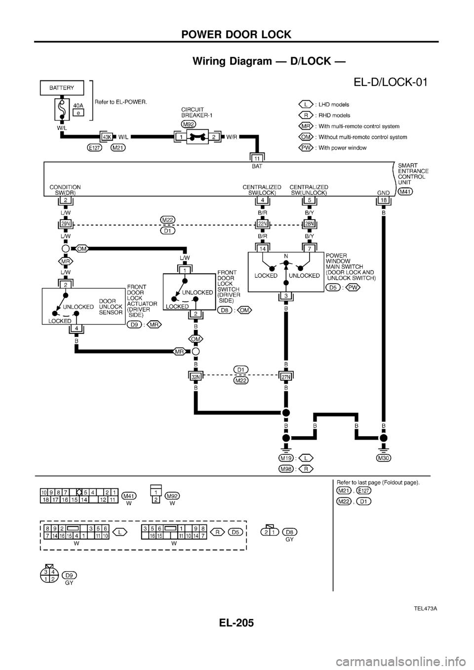
Wiring Diagram Ð D/LOCK Ð
TEL473A
POWER DOOR LOCK
EL-205
Page 210 of 326
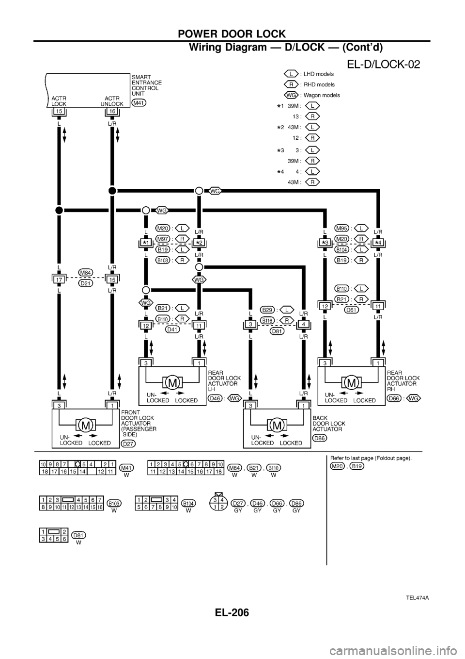
TEL474A
POWER DOOR LOCK
Wiring Diagram Ð D/LOCK Ð (Cont'd)
EL-206
Page 211 of 326
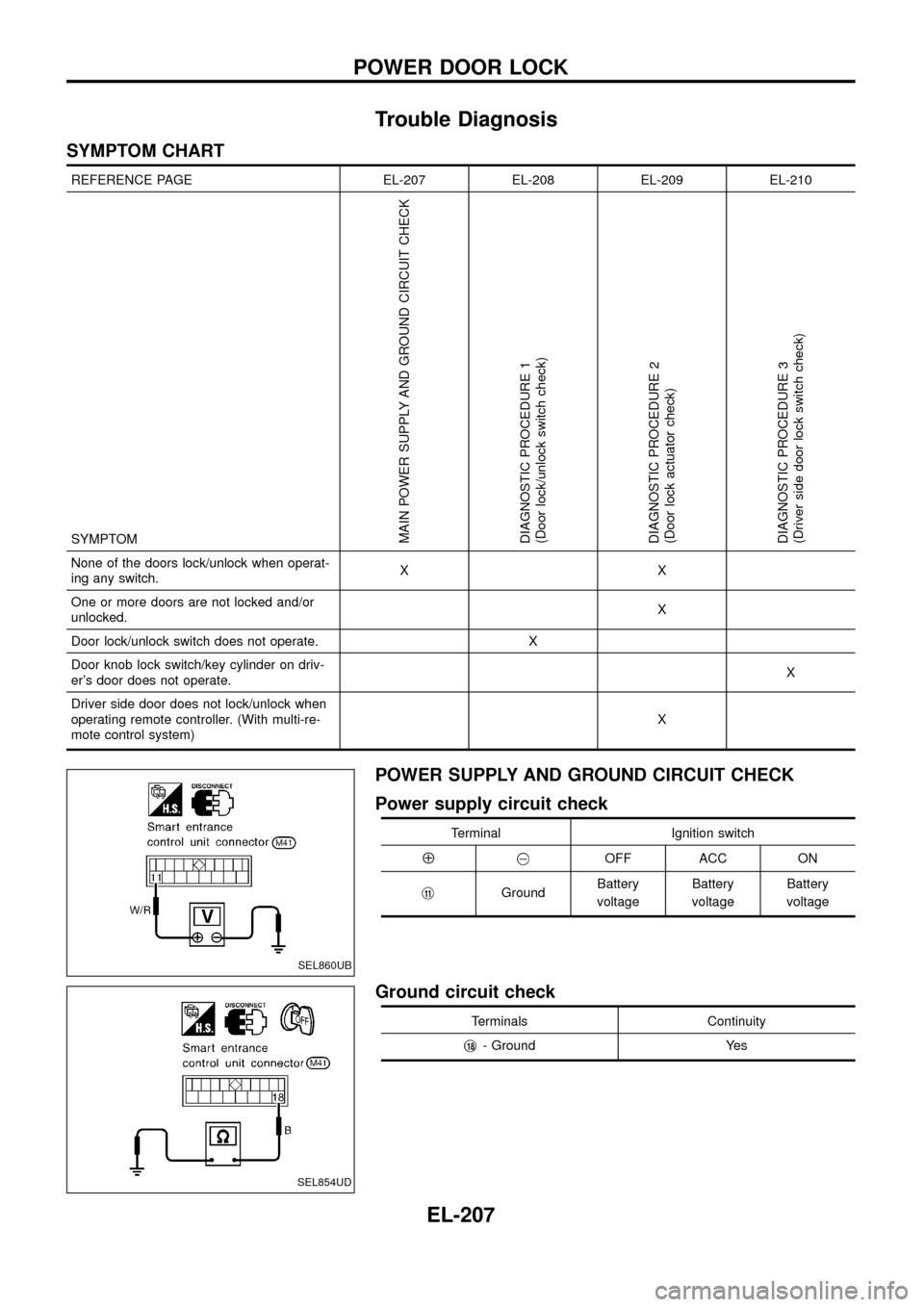
Trouble Diagnosis
SYMPTOM CHART
REFERENCE PAGE EL-207 EL-208 EL-209 EL-210
SYMPTOM
MAIN POWER SUPPLY AND GROUND CIRCUIT CHECK
DIAGNOSTIC PROCEDURE 1
(Door lock/unlock switch check)
DIAGNOSTIC PROCEDURE 2
(Door lock actuator check)
DIAGNOSTIC PROCEDURE 3
(Driver side door lock switch check)
None of the doors lock/unlock when operat-
ing any switch.XX
One or more doors are not locked and/or
unlocked.X
Door lock/unlock switch does not operate. X
Door knob lock switch/key cylinder on driv-
er's door does not operate.X
Driver side door does not lock/unlock when
operating remote controller. (With multi-re-
mote control system)X
POWER SUPPLY AND GROUND CIRCUIT CHECK
Power supply circuit check
Terminal Ignition switch
Å@OFF ACC ON
j
11GroundBattery
voltageBattery
voltageBattery
voltage
Ground circuit check
Terminals Continuity
j
18- Ground Yes
SEL860UB
SEL854UD
POWER DOOR LOCK
EL-207
Page 212 of 326
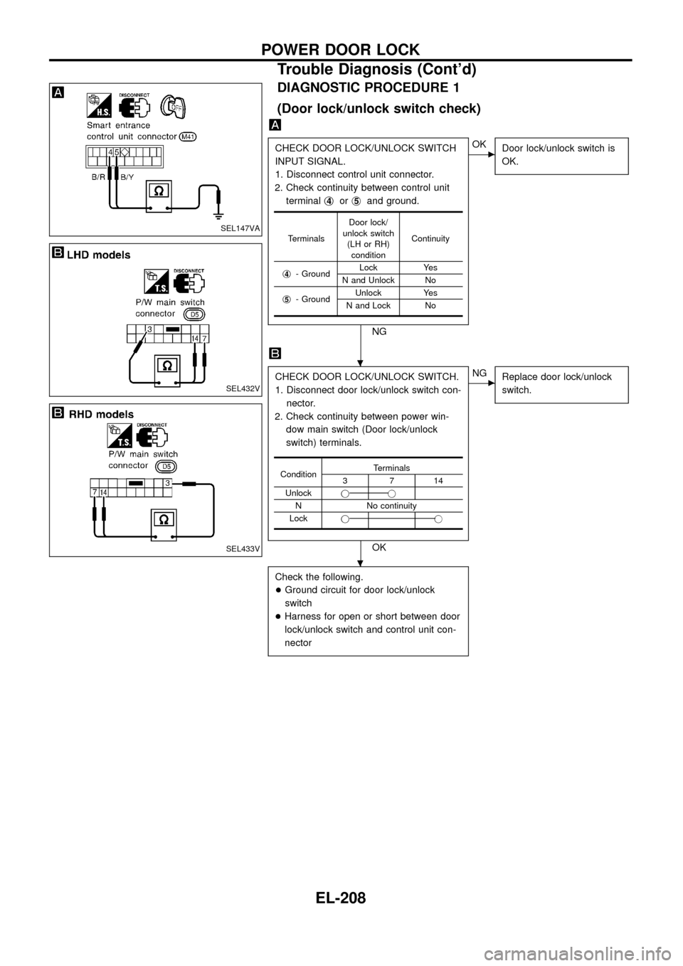
DIAGNOSTIC PROCEDURE 1
(Door lock/unlock switch check)
CHECK DOOR LOCK/UNLOCK SWITCH
INPUT SIGNAL.
1. Disconnect control unit connector.
2. Check continuity between control unit
terminalj
4orj5and ground.
NG
cOK
Door lock/unlock switch is
OK.
CHECK DOOR LOCK/UNLOCK SWITCH.
1. Disconnect door lock/unlock switch con-
nector.
2. Check continuity between power win-
dow main switch (Door lock/unlock
switch) terminals.
OK
cNG
Replace door lock/unlock
switch.
Check the following.
+Ground circuit for door lock/unlock
switch
+Harness for open or short between door
lock/unlock switch and control unit con-
nector
TerminalsDoor lock/
unlock switch
(LH or RH)
conditionContinuity
j
4- GroundLock Yes
N and Unlock No
j
5- GroundUnlock Yes
N and Lock No
ConditionTerminals3714
Unlockjj
N No continuity
Lockjj
SEL147VA
SEL432V
SEL433V
.
.
POWER DOOR LOCK
Trouble Diagnosis (Cont'd)
EL-208