change time NISSAN PATROL 1998 Y61 / 5.G Engine Control Workshop Manual
[x] Cancel search | Manufacturer: NISSAN, Model Year: 1998, Model line: PATROL, Model: NISSAN PATROL 1998 Y61 / 5.GPages: 192, PDF Size: 4.28 MB
Page 27 of 192
Test and Adjustment
WARNING:
When using nozzle tester, be careful not to allow diesel fuel
sprayed from nozzle to contact your hands or body, and make
sure your eyes are properly protected with goggles.
INJECTION PRESSURE TEST
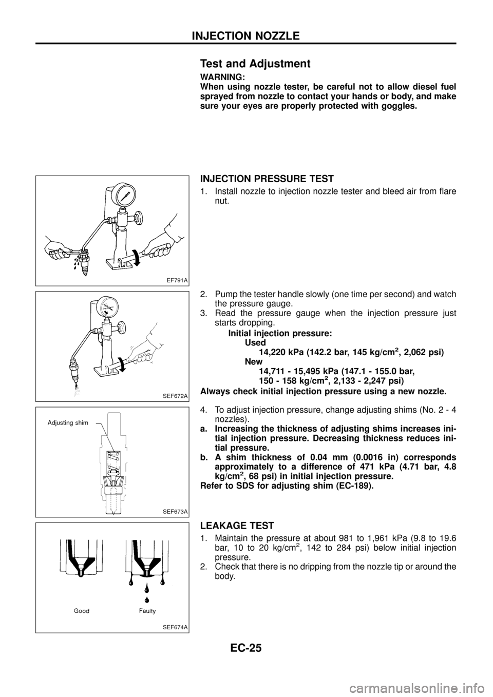
1. Install nozzle to injection nozzle tester and bleed air from ¯are
nut.
2. Pump the tester handle slowly (one time per second) and watch
the pressure gauge.
3. Read the pressure gauge when the injection pressure just
starts dropping.
Initial injection pressure:
Used
14,220 kPa (142.2 bar, 145 kg/cm
2, 2,062 psi)
New
14,711 - 15,495 kPa (147.1 - 155.0 bar,
150 - 158 kg/cm
2, 2,133 - 2,247 psi)
Always check initial injection pressure using a new nozzle.
4. To adjust injection pressure, change adjusting shims (No. 2 - 4
nozzles).
a. Increasing the thickness of adjusting shims increases ini-
tial injection pressure. Decreasing thickness reduces ini-
tial pressure.
b. A shim thickness of 0.04 mm (0.0016 in) corresponds
approximately to a difference of 471 kPa (4.71 bar, 4.8
kg/cm
2, 68 psi) in initial injection pressure.
Refer to SDS for adjusting shim (EC-189).
LEAKAGE TEST
1. Maintain the pressure at about 981 to 1,961 kPa (9.8 to 19.6
bar, 10 to 20 kg/cm2, 142 to 284 psi) below initial injection
pressure.
2. Check that there is no dripping from the nozzle tip or around the
body.
EF791A
SEF672A
SEF673A
Adjusting shim
SEF674A
INJECTION NOZZLE
EC-25
Page 32 of 192
DTC and MIL Detection Logic
When a malfunction is detected for the ®rst time, the malfunction (DTC) is stored in the ECM memory.
The MIL will light up each time the ECM detects malfunction. However, if the same malfunction is experienced
in two consecutive driving patterns and the engine is still running, the MIL will stay lit up. For diagnostic items
causing the MIL to light up, refer to ``DIAGNOSTIC TROUBLE CODE INDEX'', EC-1.
Diagnostic Trouble Code (DTC)
HOW TO READ DTC
The diagnostic trouble code can be read by the following methods.
1. The number of blinks of the malfunction indicator lamp in the Diagnostic Test Mode II (Self-Diagnostic
Results) Examples: 11, 13, 14, etc.
These DTCs are controlled by NISSAN.
2. CONSULT Examples: ``CAM POS SEN (PUMP)'', etc.
+Output of the trouble code means that the indicated circuit has a malfunction. However, in the Mode
II it does not indicate whether the malfunction is still occurring or occurred in the past and returned
to normal.
CONSULT can identify them. Therefore, using CONSULT (if available) is recommended.
HOW TO ERASE DTC
The diagnostic trouble code can be erased by the following methods.
Selecting ``ERASE'' in the ``SELF-DIAG RESULTS'' mode with CONSULT.
Changing the diagnostic test mode from Diagnostic Test Mode II to Mode I. (Refer to EC-32.)
+If the battery terminal is disconnected, the diagnostic trouble code will be lost within 24 hours.
+When you erase the DTC, using CONSULT is easier and quicker than switching the diagnostic test
modes.
HOW TO ERASE DTC (With CONSULT)
1. If the ignition switch stays ``ON'' after repair work, be sure to turn ignition switch ``OFF'' once. Wait at least
5 seconds and then turn it ``ON'' (Engine stopped) again.
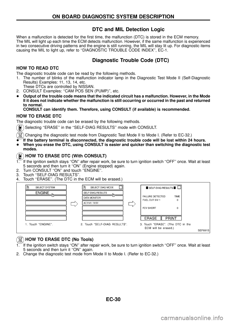
2. Turn CONSULT ``ON'' and touch ``ENGINE''.
3. Touch ``SELF-DIAG RESULTS''.
4. Touch ``ERASE''. (The DTC in the ECM will be erased.)
HOW TO ERASE DTC (No Tools)
1. If the ignition switch stays ``ON'' after repair work, be sure to turn ignition switch ``OFF'' once. Wait at least
5 seconds and then turn it ``ON'' again.
2. Change the diagnostic test mode from Mode II to Mode I. (Refer to EC-32.)
SEF691S
ON BOARD DIAGNOSTIC SYSTEM DESCRIPTION
EC-30
Page 36 of 192
DIAGNOSTIC TEST MODE IÐBULB CHECK
In this mode, the MALFUNCTION INDICATOR LAMP on the instrument panel should stay ON. If it remains
OFF, check the bulb. Refer to EL section (``WARNING LAMPS AND CHIME'') or see EC-188.
DIAGNOSTIC TEST MODE IÐMALFUNCTION WARNING
MALFUNCTION
INDICATOR LAMPCondition
ONWhen the malfunction is detected or the ECM's CPU is malfunctioning. (Refer to ``MIL Illumination'' of the
``DIAGNOSTIC TROUBLE CODE INDEX'', EC-1.)
OFF No malfunction.
+These Diagnostic Trouble Code Numbers are clari®ed in Diagnostic Test Mode II (SELF-DIAGNOSTIC
RESULTS).
DIAGNOSTIC TEST MODE IIÐSELF-DIAGNOSTIC RESULTS
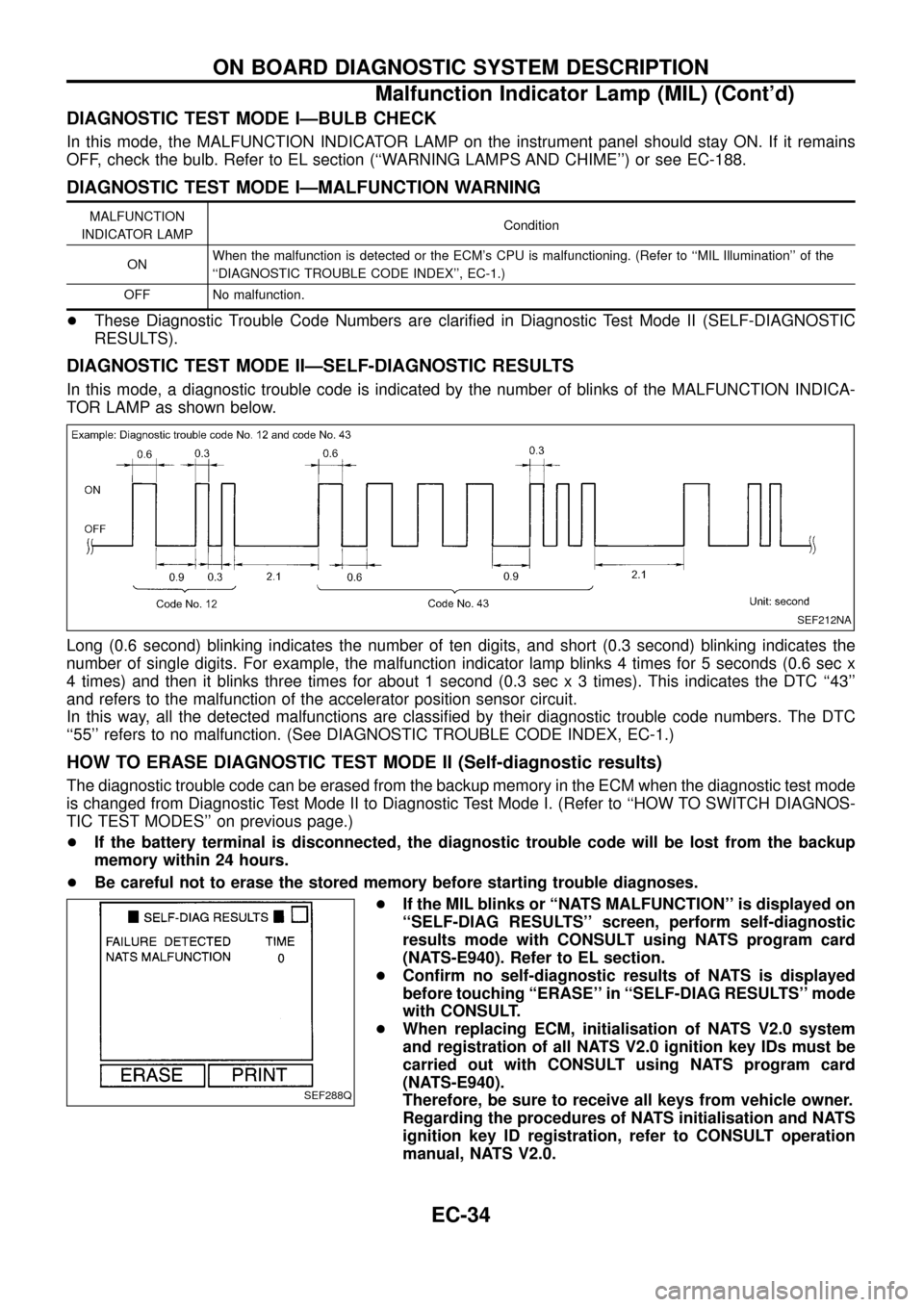
In this mode, a diagnostic trouble code is indicated by the number of blinks of the MALFUNCTION INDICA-
TOR LAMP as shown below.
Long (0.6 second) blinking indicates the number of ten digits, and short (0.3 second) blinking indicates the
number of single digits. For example, the malfunction indicator lamp blinks 4 times for 5 seconds (0.6 sec x
4 times) and then it blinks three times for about 1 second (0.3 sec x 3 times). This indicates the DTC ``43''
and refers to the malfunction of the accelerator position sensor circuit.
In this way, all the detected malfunctions are classi®ed by their diagnostic trouble code numbers. The DTC
``55'' refers to no malfunction. (See DIAGNOSTIC TROUBLE CODE INDEX, EC-1.)
HOW TO ERASE DIAGNOSTIC TEST MODE II (Self-diagnostic results)
The diagnostic trouble code can be erased from the backup memory in the ECM when the diagnostic test mode
is changed from Diagnostic Test Mode II to Diagnostic Test Mode I. (Refer to ``HOW TO SWITCH DIAGNOS-
TIC TEST MODES'' on previous page.)
+If the battery terminal is disconnected, the diagnostic trouble code will be lost from the backup
memory within 24 hours.
+Be careful not to erase the stored memory before starting trouble diagnoses.
+If the MIL blinks or ``NATS MALFUNCTION'' is displayed on
``SELF-DIAG RESULTS'' screen, perform self-diagnostic
results mode with CONSULT using NATS program card
(NATS-E940). Refer to EL section.
+Con®rm no self-diagnostic results of NATS is displayed
before touching ``ERASE'' in ``SELF-DIAG RESULTS'' mode
with CONSULT.
+When replacing ECM, initialisation of NATS V2.0 system
and registration of all NATS V2.0 ignition key IDs must be
carried out with CONSULT using NATS program card
(NATS-E940).
Therefore, be sure to receive all keys from vehicle owner.
Regarding the procedures of NATS initialisation and NATS
ignition key ID registration, refer to CONSULT operation
manual, NATS V2.0.
SEF212NA
SEF288Q
ON BOARD DIAGNOSTIC SYSTEM DESCRIPTION
Malfunction Indicator Lamp (MIL) (Cont'd)
EC-34
Page 103 of 192
Injection Timing Control Valve
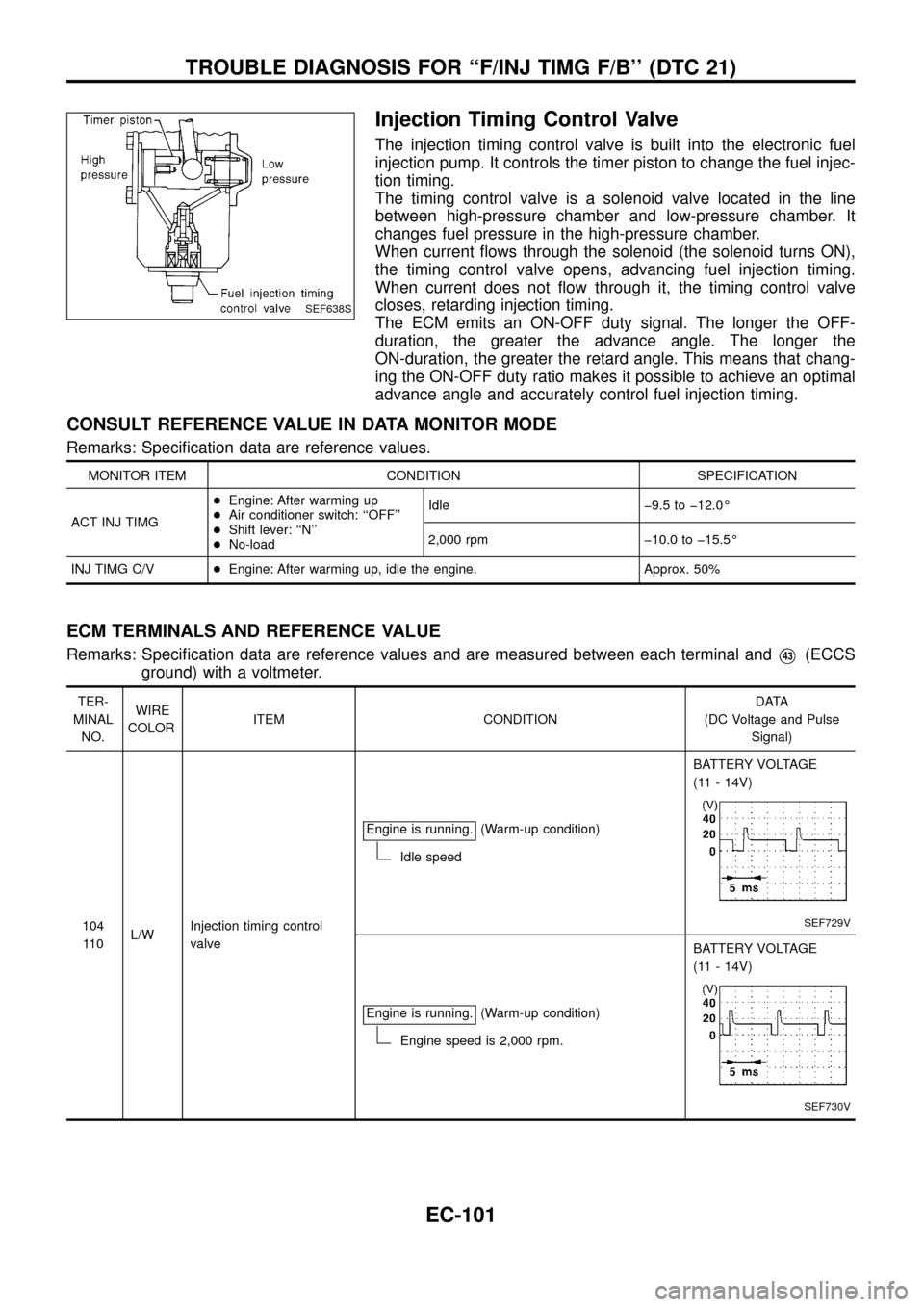
The injection timing control valve is built into the electronic fuel
injection pump. It controls the timer piston to change the fuel injec-
tion timing.
The timing control valve is a solenoid valve located in the line
between high-pressure chamber and low-pressure chamber. It
changes fuel pressure in the high-pressure chamber.
When current ¯ows through the solenoid (the solenoid turns ON),
the timing control valve opens, advancing fuel injection timing.
When current does not ¯ow through it, the timing control valve
closes, retarding injection timing.
The ECM emits an ON-OFF duty signal. The longer the OFF-
duration, the greater the advance angle. The longer the
ON-duration, the greater the retard angle. This means that chang-
ing the ON-OFF duty ratio makes it possible to achieve an optimal
advance angle and accurately control fuel injection timing.
CONSULT REFERENCE VALUE IN DATA MONITOR MODE
Remarks: Speci®cation data are reference values.
MONITOR ITEM CONDITION SPECIFICATION
ACT INJ TIMG+Engine: After warming up
+Air conditioner switch: ``OFF''
+Shift lever: ``N''
+No-loadIdle þ9.5 to þ12.0É
2,000 rpm þ10.0 to þ15.5É
INJ TIMG C/V+Engine: After warming up, idle the engine. Approx. 50%
ECM TERMINALS AND REFERENCE VALUE
Remarks: Speci®cation data are reference values and are measured between each terminal andV43(ECCS
ground) with a voltmeter.
TER-
MINAL
NO.WIRE
COLORITEM CONDITIONDATA
(DC Voltage and Pulse
Signal)
104
11 0L/WInjection timing control
valveEngine is running.
(Warm-up condition)
Idle speedBATTERY VOLTAGE
(11 - 14V)
SEF729V
Engine is running.(Warm-up condition)
Engine speed is 2,000 rpm.BATTERY VOLTAGE
(11 - 14V)
SEF730V
SEF638S
TROUBLE DIAGNOSIS FOR ``F/INJ TIMG F/B'' (DTC 21)
EC-101
Page 156 of 192
jA
CHECK COMPONENTS
(Glow relay, Glow plug).
Refer to ``COMPONENT INSPECTION'',
EC-155.
OK
cNG
Replace malfunctioning
component(s).
Disconnect and reconnect harness connec-
tors in the circuit. Then retest.
Trouble is not ®xed.
Check ECM pin terminals for damage and
check the connection of ECM harness con-
nector. Reconnect ECM harness connector
and retest.
INSPECTION END
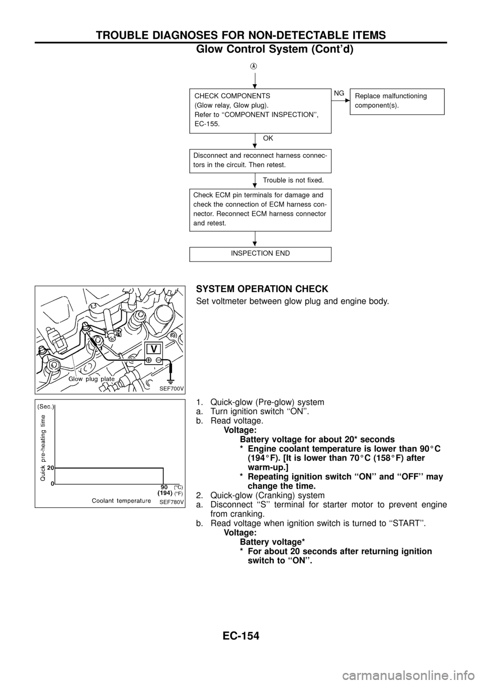
SYSTEM OPERATION CHECK
Set voltmeter between glow plug and engine body.
1. Quick-glow (Pre-glow) system
a. Turn ignition switch ``ON''.
b. Read voltage.
Voltage:
Battery voltage for about 20* seconds
* Engine coolant temperature is lower than 90ÉC
(194ÉF). [It is lower than 70ÉC (158ÉF) after
warm-up.]
* Repeating ignition switch ``ON'' and ``OFF'' may
change the time.
2. Quick-glow (Cranking) system
a. Disconnect ``S'' terminal for starter motor to prevent engine
from cranking.
b. Read voltage when ignition switch is turned to ``START''.
Voltage:
Battery voltage*
* For about 20 seconds after returning ignition
switch to ``ON''.
SEF700V
SEF780V
.
.
.
.
TROUBLE DIAGNOSES FOR NON-DETECTABLE ITEMS
Glow Control System (Cont'd)
EC-154