light NISSAN PATROL 1998 Y61 / 5.G General Information Workshop Manual
[x] Cancel search | Manufacturer: NISSAN, Model Year: 1998, Model line: PATROL, Model: NISSAN PATROL 1998 Y61 / 5.GPages: 47, PDF Size: 1.07 MB
Page 11 of 47

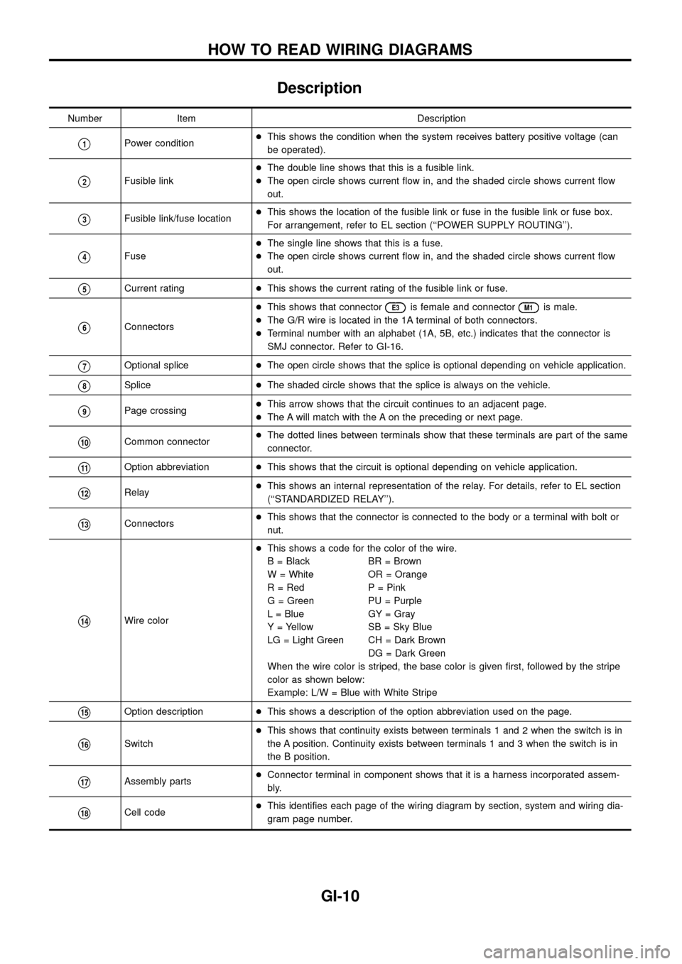
Description
Number Item Description
V1Power condition+This shows the condition when the system receives battery positive voltage (can
be operated).
V2Fusible link+The double line shows that this is a fusible link.
+The open circle shows current ¯ow in, and the shaded circle shows current ¯ow
out.
V3Fusible link/fuse location+This shows the location of the fusible link or fuse in the fusible link or fuse box.
For arrangement, refer to EL section (``POWER SUPPLY ROUTING'').
V4Fuse+The single line shows that this is a fuse.
+The open circle shows current ¯ow in, and the shaded circle shows current ¯ow
out.
V5Current rating+This shows the current rating of the fusible link or fuse.
V6Connectors+This shows that connector
E3is female and connectorM1is male.
+The G/R wire is located in the 1A terminal of both connectors.
+Terminal number with an alphabet (1A, 5B, etc.) indicates that the connector is
SMJ connector. Refer to GI-16.
V7Optional splice+The open circle shows that the splice is optional depending on vehicle application.
V8Splice+The shaded circle shows that the splice is always on the vehicle.
V9Page crossing+This arrow shows that the circuit continues to an adjacent page.
+The A will match with the A on the preceding or next page.
V10Common connector+The dotted lines between terminals show that these terminals are part of the same
connector.
V11Option abbreviation+This shows that the circuit is optional depending on vehicle application.
V12Relay+This shows an internal representation of the relay. For details, refer to EL section
(``STANDARDIZED RELAY'').
V13Connectors+This shows that the connector is connected to the body or a terminal with bolt or
nut.
V14Wire color+This shows a code for the color of the wire.
B = Black BR = Brown
W = White OR = Orange
R = Red P = Pink
G = Green PU = Purple
L = Blue GY = Gray
Y = Yellow SB = Sky Blue
LG = Light Green CH = Dark Brown
DG = Dark Green
When the wire color is striped, the base color is given ®rst, followed by the stripe
color as shown below:
Example: L/W = Blue with White Stripe
V15Option description+This shows a description of the option abbreviation used on the page.
V16Switch+This shows that continuity exists between terminals 1 and 2 when the switch is in
the A position. Continuity exists between terminals 1 and 3 when the switch is in
the B position.
V17Assembly parts+Connector terminal in component shows that it is a harness incorporated assem-
bly.
V18Cell code+This identi®es each page of the wiring diagram by section, system and wiring dia-
gram page number.
HOW TO READ WIRING DIAGRAMS
GI-10
Page 22 of 47

Incident Simulation Tests
INTRODUCTION
Sometimes the symptom is not present when the vehicle is brought in for service. If possible, re-create the
conditions present at the time of the incident. Doing so may help avoid a No Trouble Found Diagnosis. The
following section illustrates ways to simulate the conditions/environment under which the owner experiences
an electrical incident.
The section is broken into the six following topics:
+Vehicle vibration
+Heat sensitive
+Freezing
+Water intrusion
+Electrical load
+Cold or hot start up
Get a thorough description of the incident from the customer. It is important for simulating the conditions of
the problem.
VEHICLE VIBRATION
The problem may occur or become worse while driving on a rough road or when engine is vibrating (idle with
A/C on). In such a case, you will want to check for a vibration related condition. Refer to the illustration below.
Connectors & harness
Determine which connectors and wiring harness would affect the electrical system you are inspecting.Gen-
tlyshake each connector and harness while monitoring the system for the incident you are trying to dupli-
cate. This test may indicate a loose or poor electrical connection.
Hint
Connectors can be exposed to moisture. It is possible to get a thin ®lm of corrosion on the connector termi-
nals. A visual inspection may not reveal this without disconnecting the connector. If the problem occurs
intermittently, perhaps the problem is caused by corrosion. It is a good idea to disconnect, inspect and clean
the terminals on related connectors in the system.
Sensors & relays
Gentlyapply a slight vibration to sensors and relays in the system you are inspecting.
This test may indicate a loose or poorly mounted sensor or relay.
SGI839
HOW TO PERFORM EFFICIENT DIAGNOSIS FOR AN ELECTRICAL INCIDENT
GI-21
Page 28 of 47

VOLTAGE DROP TESTS
Voltage drop tests are often used to ®nd components or circuits which have excessive resistance. A voltage
drop in a circuit is caused by a resistancewhen the circuit is in operation.
Check the wire in the illustration. When measuring resistance with ohmmeter, contact by a single strand of
wire will give reading of 0 ohms. This would indicate a good circuit. When the circuit operates, this single strand
of wire is not able to carry the current. The single strand will have a high resistance to the current. This will
be picked up as a slight voltage drop.
Unwanted resistance can be caused by many situations as follows:
Undersized wiring (single strand example)
Corrosion on switch contacts
Loose wire connections or splices.
If repairs are needed always use wire that is of the same or larger gauge.
Measuring voltage drop Ð Accumulated method
1. Connect the voltmeter across the connector or part of the circuit you want to check. The positive lead of
the voltmeter should be closer to power and the negative lead closer to ground.
2. Operate the circuit.
3. The voltmeter will indicate how many volts are being used to ``push'' current through that part of the cir-
cuit.
Note in the illustration that there is an excessive 4.1 volt drop between the battery and the bulb.
Measuring voltage drop Ð Step by step
The step by step method is most useful for isolating excessive drops in low voltage systems (such as those
in ``Computer Controlled Systems'').
Circuits in the ``Computer Controlled System'' operate on very low amperage.
The (Computer Controlled) system operations can be adversely affected by any variation in resistance in the
system. Such resistance variation may be caused by poor connection, improper installation, improper wire
gauge or corrosion.
The step by step voltage drop test can identify a component or wire with too much resistance.
SGI974
HOW TO PERFORM EFFICIENT DIAGNOSIS FOR AN ELECTRICAL INCIDENT
Circuit Inspection (Cont'd)
GI-27
Page 30 of 47

CONTROL UNIT CIRCUIT TEST
System Description: When the switch is ON, the control unit lights up the lamp.
AGI059
HOW TO PERFORM EFFICIENT DIAGNOSIS FOR AN ELECTRICAL INCIDENT
Circuit Inspection (Cont'd)
GI-29
Page 45 of 47

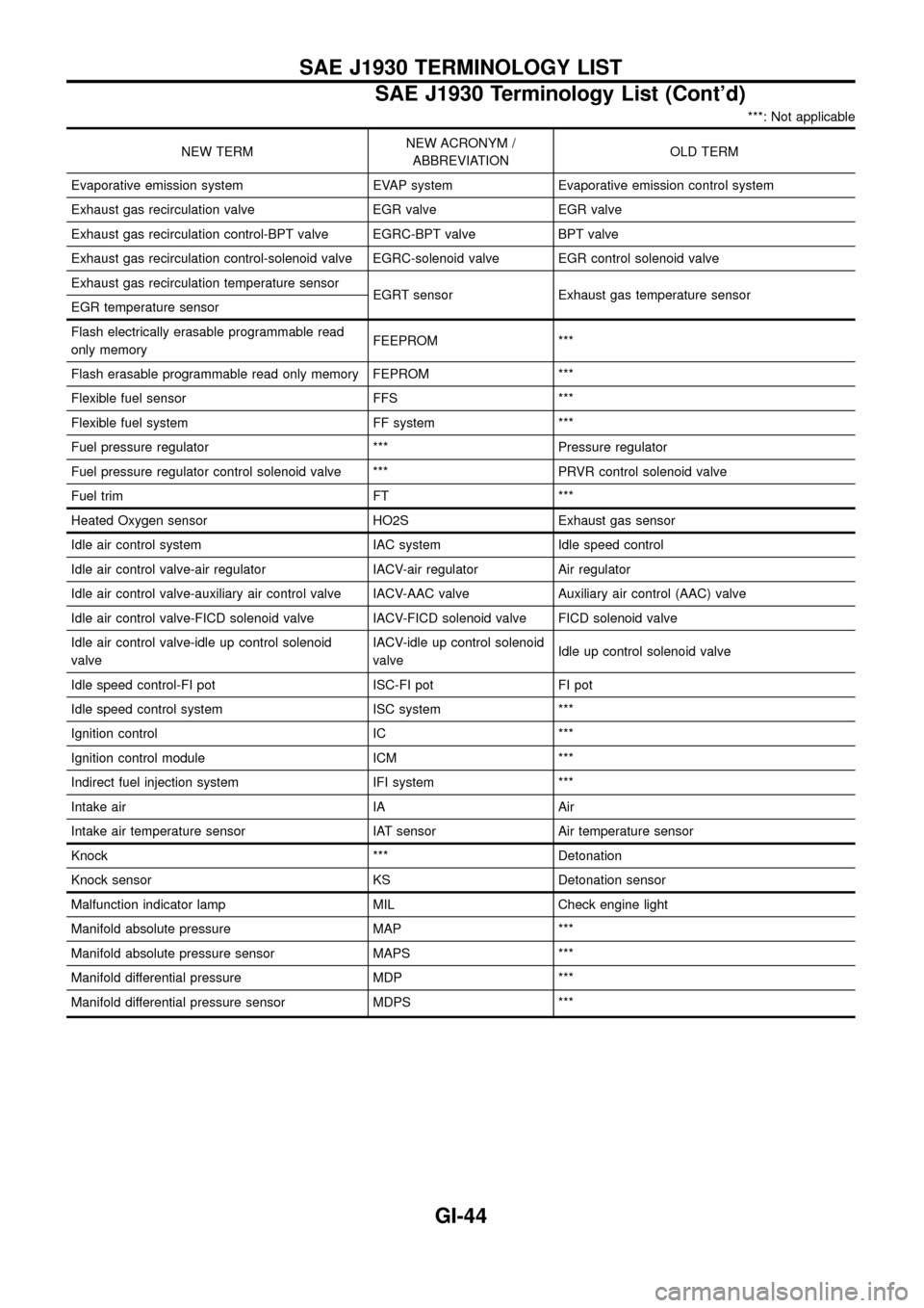
***: Not applicable
NEW TERMNEW ACRONYM /
ABBREVIATIONOLD TERM
Evaporative emission system EVAP system Evaporative emission control system
Exhaust gas recirculation valve EGR valve EGR valve
Exhaust gas recirculation control-BPT valve EGRC-BPT valve BPT valve
Exhaust gas recirculation control-solenoid valve EGRC-solenoid valve EGR control solenoid valve
Exhaust gas recirculation temperature sensor
EGRT sensor Exhaust gas temperature sensor
EGR temperature sensor
Flash electrically erasable programmable read
only memoryFEEPROM ***
Flash erasable programmable read only memory FEPROM ***
Flexible fuel sensor FFS ***
Flexible fuel system FF system ***
Fuel pressure regulator *** Pressure regulator
Fuel pressure regulator control solenoid valve *** PRVR control solenoid valve
Fuel trim FT ***
Heated Oxygen sensor HO2S Exhaust gas sensor
Idle air control system IAC system Idle speed control
Idle air control valve-air regulator IACV-air regulator Air regulator
Idle air control valve-auxiliary air control valve IACV-AAC valve Auxiliary air control (AAC) valve
Idle air control valve-FICD solenoid valve IACV-FICD solenoid valve FICD solenoid valve
Idle air control valve-idle up control solenoid
valveIACV-idle up control solenoid
valveIdle up control solenoid valve
Idle speed control-FI pot ISC-FI pot FI pot
Idle speed control system ISC system ***
Ignition control IC ***
Ignition control module ICM ***
Indirect fuel injection system IFI system ***
Intake air IA Air
Intake air temperature sensor IAT sensor Air temperature sensor
Knock *** Detonation
Knock sensor KS Detonation sensor
Malfunction indicator lamp MIL Check engine light
Manifold absolute pressure MAP ***
Manifold absolute pressure sensor MAPS ***
Manifold differential pressure MDP ***
Manifold differential pressure sensor MDPS ***
SAE J1930 TERMINOLOGY LIST
SAE J1930 Terminology List (Cont'd)
GI-44