NISSAN PATROL 1998 Y61 / 5.G Body Workshop Manual
Manufacturer: NISSAN, Model Year: 1998, Model line: PATROL, Model: NISSAN PATROL 1998 Y61 / 5.GPages: 55, PDF Size: 2.76 MB
Page 1 of 55
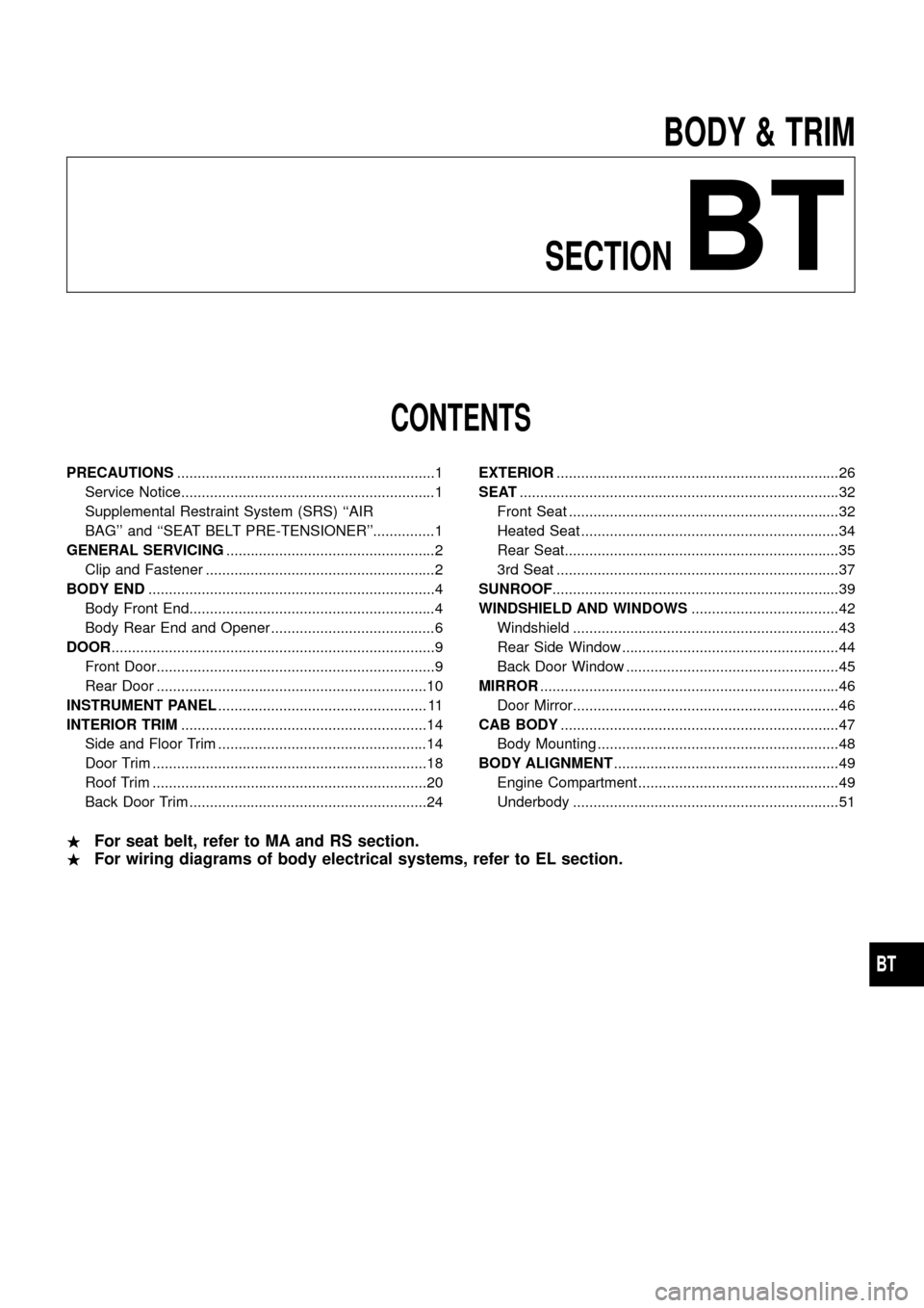
BODY & TRIM
SECTION
BT
CONTENTS
PRECAUTIONS ...............................................................1
Service Notice..............................................................1
Supplemental Restraint System (SRS) ``AIR
BAG''and``SEATBELTPRE-TENSIONER''...............1
GENERAL SERVICING ...................................................2
Clip and Fastener ........................................................2
BODY END ......................................................................4
Body Front End............................................................4
Body Rear End and Opener ........................................6
DOOR ........................................................................\
.......9
Front Door....................................................................9
Rear Door ..................................................................10
INSTRUMENT PANEL ................................................... 11
INTERIOR TRIM ............................................................14
Side and Floor Trim ...................................................14
Door Trim ...................................................................18
Roof Trim ...................................................................20
Back Door Trim ..........................................................24 EXTERIOR
.....................................................................26
SEAT ........................................................................\
......32
Front Seat ..................................................................32
Heated Seat ...............................................................34
Rear Seat...................................................................35
3rd Seat .....................................................................37
SUNROOF ......................................................................39
WINDSHIELD AND WINDOWS ....................................42
Windshield .................................................................43
Rear Side Window .....................................................44
Back Door Window ....................................................45
MIRROR ........................................................................\
.46
Door Mirror.................................................................46
CAB BODY ....................................................................47
Body Mounting ...........................................................48
BODY ALIGNMENT .......................................................49
Engine Compartment .................................................49
Underbody .................................................................51
. For seat belt, refer to MA and RS section.
. For wiring diagrams of body electrical systems, refer to EL section.
BT
Page 2 of 55
Service Notice
+When removing or installing various parts, place a cloth or padding onto the vehicle body to prevent
scratches.
+Handle trim, molding, instruments, grille, etc. carefully during removing or installing. Be careful not to soil
or damage them.
+Apply sealing compound where necessary when installing parts.
+When applying sealing compound, be careful that the sealing compound does not protrude from parts.
+When replacing any metal parts (for example body outer panel, members, etc.), be sure to take rust pre-
vention measures.
Supplemental Restraint System (SRS) ``AIR
BAG'' and ``SEAT BELT PRE-TENSIONER''
The Supplemental Restraint System such as ``AIR BAG'' and ``SEAT BELT PRE-TENSIONER'' used along with
a seat belt, helps to reduce the risk or severity of injury to the driver and front passenger in a frontal collision.
The SRS system composition which is available to NISSAN MODEL Y61 is as follows (The composition var-
ies according to the destination.):
Driver air bag module (located in the center of the steering wheel), front passenger air bag module (located
on the instrument panel on passenger side), seat belt pre-tensioner, a diagnosis sensor unit, warning lamp,
wiring harness and spiral cable.
Information necessary to service the system safely is included in theRS sectionof this Service Manual.
WARNING:
+To avoid rendering the SRS inoperative, which could increase the risk of personal injury or death
in the event of a collision which would result in air bag in¯ation, all maintenance must be performed
by an authorized NISSAN dealer.
+Improper maintenance, including incorrect removal and installation of the SRS, can lead to per-
sonal injury caused by unintentional activation of the system. For removal of Spiral Cable and Air
Bag Module, see the RS section.
+Do not use electrical test equipment on any circuit related to the SRS unless instructed to in this
Service Manual. Spiral cable and wiring harnesses covered with yellow insulation either just before
the harness connectors or for the complete harness are related to the SRS.
PRECAUTIONS
BT-1
Page 3 of 55
Clip and Fastener
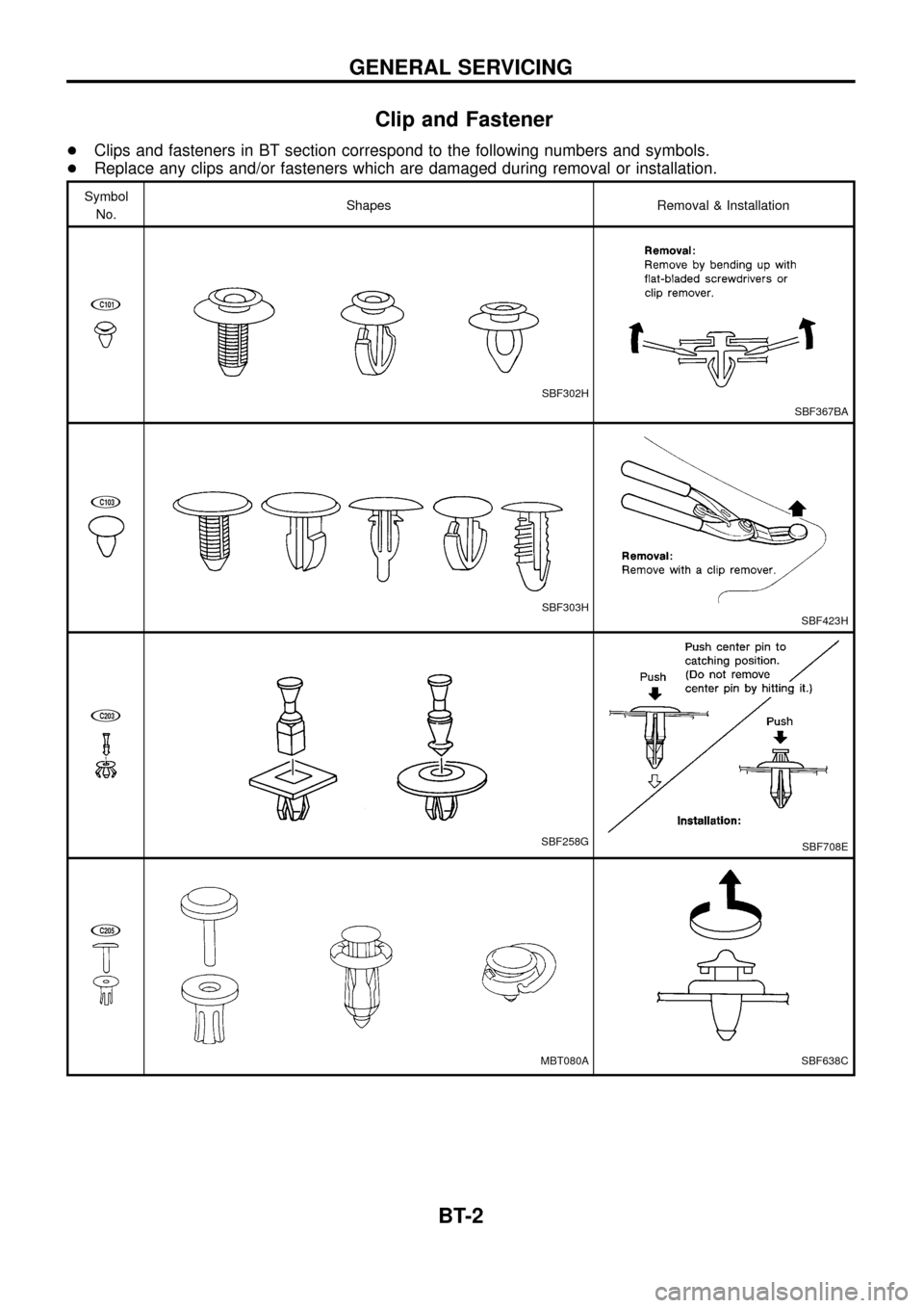
+Clips and fasteners in BT section correspond to the following numbers and symbols.
+Replace any clips and/or fasteners which are damaged during removal or installation.
Symbol
No.Shapes Removal & Installation
jC101
SBF302H
SBF367BA
jC103
SBF303HSBF423H
jC203
SBF258GSBF708E
jC205
MBT080ASBF638C
GENERAL SERVICING
BT-2
Page 4 of 55
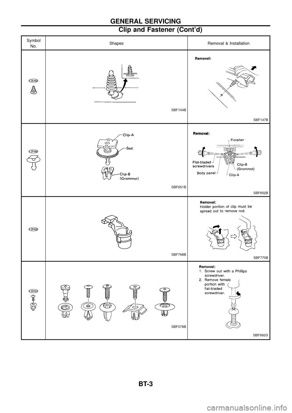
Symbol
No.Shapes Removal & Installation
jCE103
SBF104B
SBF147B
jCF109
SBF651B
SBF652B
jCR103
SBF768BSBF770B
jCS101
SBF078B
SBF992G
GENERAL SERVICING
Clip and Fastener (Cont'd)
BT-3
Page 5 of 55
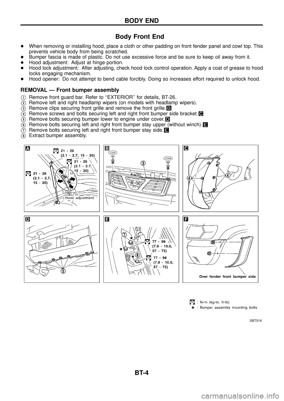
Body Front End
+When removing or installing hood, place a cloth or other padding on front fender panel and cowl top. This
prevents vehicle body from being scratched.
+Bumper fascia is made of plastic. Do not use excessive force and be sure to keep oil away from it.
+Hood adjustment: Adjust at hinge portion.
+Hood lock adjustment: After adjusting, check hood lock control operation. Apply a coat of grease to hood
locks engaging mechanism.
+Hood opener: Do not attempt to bend cable forcibly. Doing so increases effort required to unlock hood.
REMOVAL Ð Front bumper assembly
V1Remove front guard bar. Refer to ``EXTERIOR'' for details, BT-26.
V2Remove left and right headlamp wipers (on models with headlamp wipers).
V3Remove clips securing front grille and remove the front grille.
V4Remove screws and bolts securing left and right front bumper side bracket.
V5Remove bolts securing bumper lower to engine under cover.
V6Remove bolts securing left and right front bumper stay upper (without winch).
V7Remove bolts securing left and right front bumper stay side.
V8Extract bumper assembly.
SBT518
BODY END
BT-4
Page 6 of 55
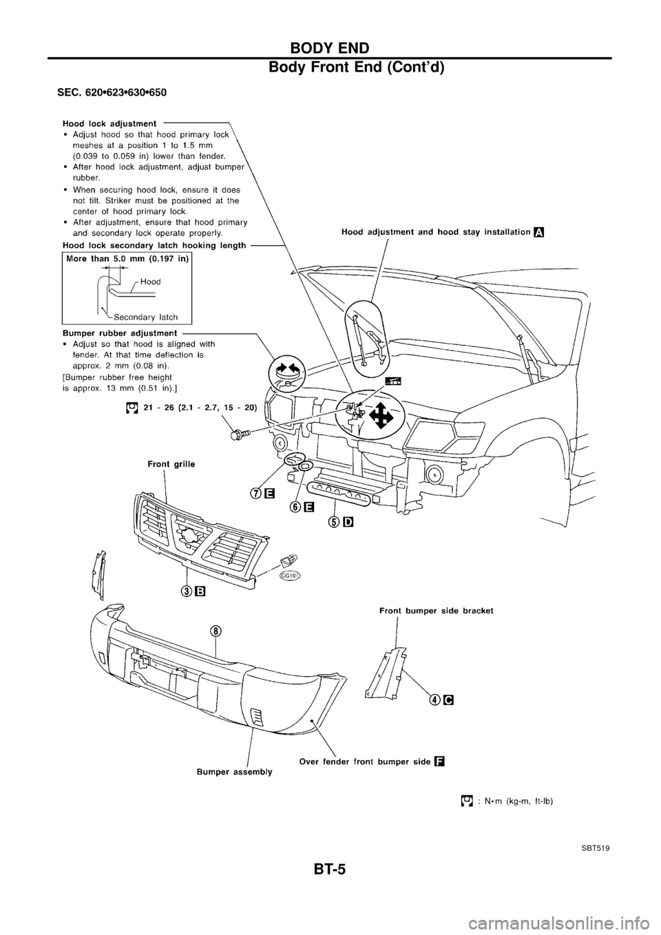
SBT519
BODY END
Body Front End (Cont'd)
BT-5
Page 7 of 55
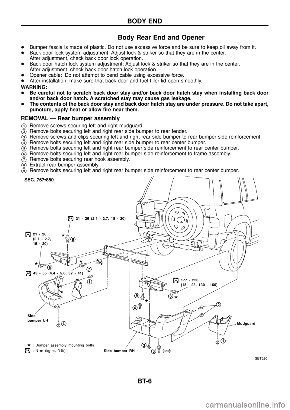
Body Rear End and Opener
+Bumper fascia is made of plastic. Do not use excessive force and be sure to keep oil away from it.
+Back door lock system adjustment: Adjust lock & striker so that they are in the center.
After adjustment, check back door lock operation.
+Back door hatch lock system adjustment: Adjust lock & striker so that they are in the center.
After adjustment, check back door hatch lock operation.
+Opener cable: Do not attempt to bend cable using excessive force.
+After installation, make sure that back door and fuel ®ller lid open smoothly.
WARNING:
+Be careful not to scratch back door stay and/or back door hatch stay when installing back door
and/or back door hatch. A scratched stay may cause gas leakage.
+The contents of the back door stay and back door hatch stay are under pressure. Do not take apart,
puncture, apply heat or allow ®re near them.
REMOVAL Ð Rear bumper assembly
V1Remove screws securing left and right mudguard.
V2Remove bolts securing left and right rear side bumper to rear fender.
V3Remove screws and clips securing left and right rear side bumper to rear bumper side reinforcement.
V4Remove bolts securing left and right rear side bumper to rear center bumper.
V5Remove bolts securing left and right rear bumper side reinforcement to rear center bumper.
V6Remove bolts securing left and right rear bumper side reinforcement to frame assembly.
V7Remove bolts securing rear hook assembly.
V8Extract rear bumper assembly.
V9Remove bolts securing left and right rear bumper side reinforcement to rear center bumper.
SBT520
BODY END
BT-6
Page 8 of 55
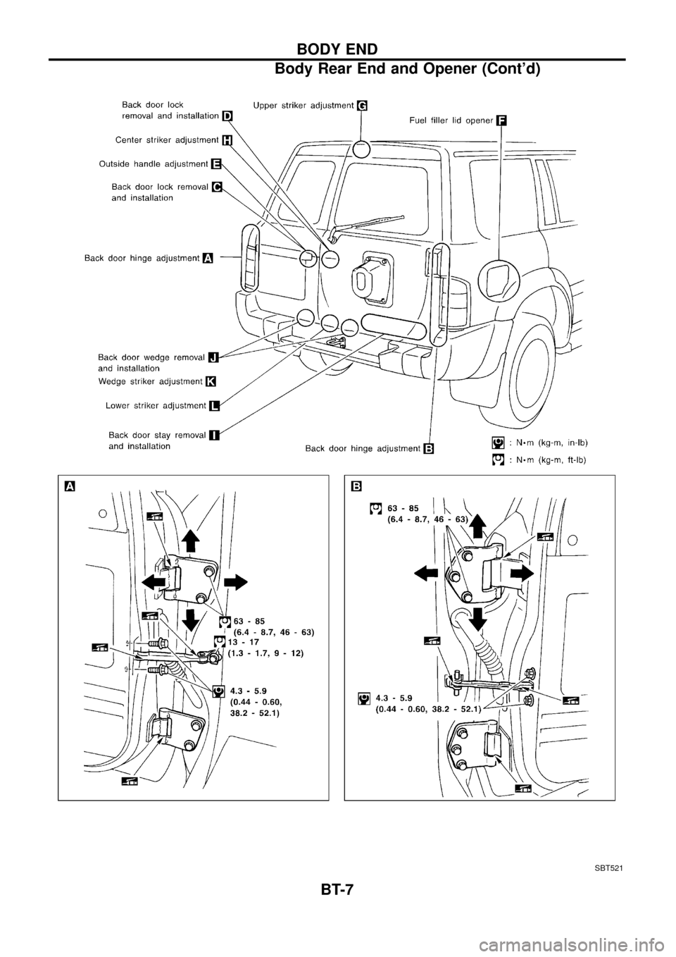
SBT521
BODY END
Body Rear End and Opener (Cont'd)
BT-7
Page 9 of 55
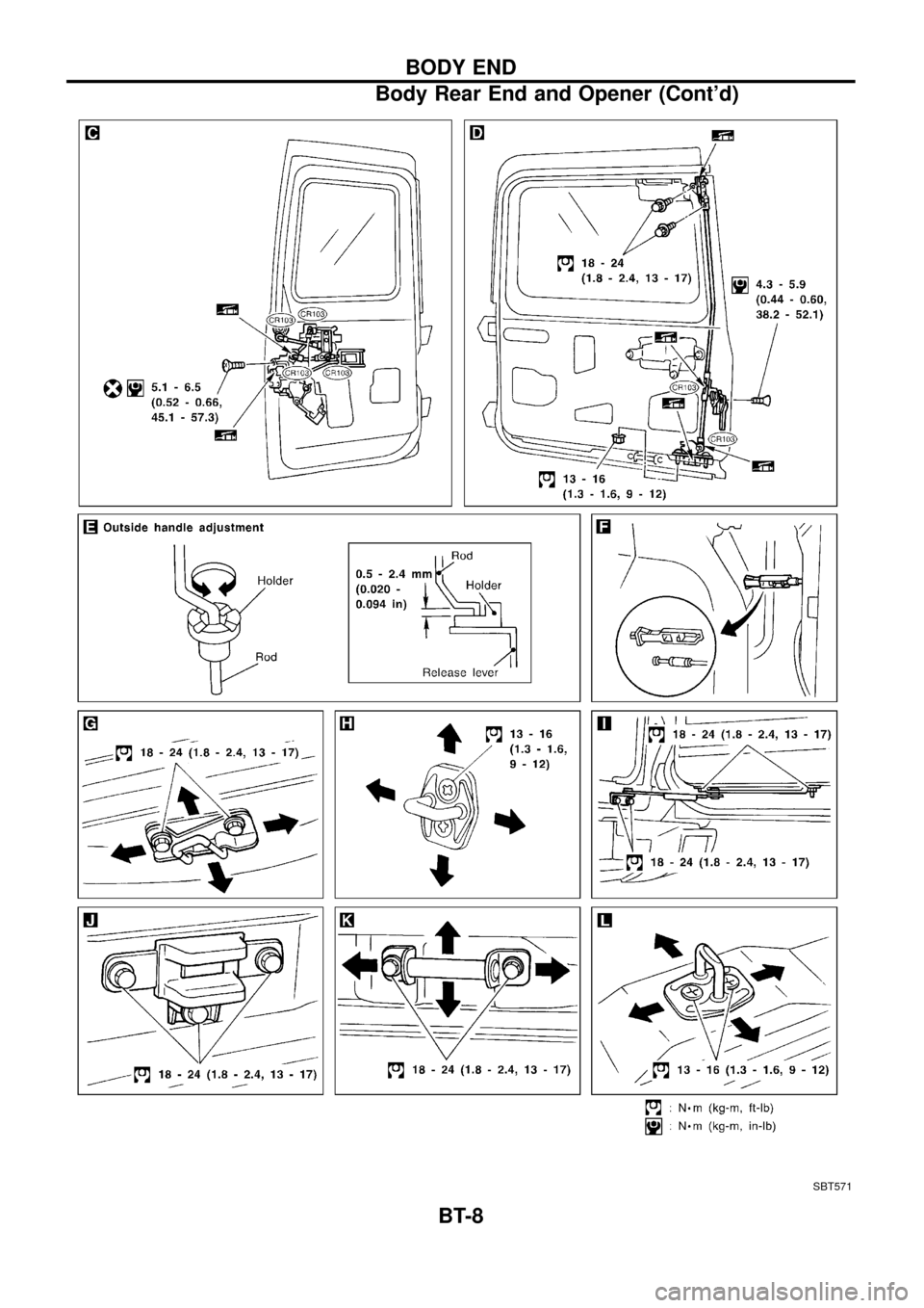
SBT571
BODY END
Body Rear End and Opener (Cont'd)
BT-8
Page 10 of 55
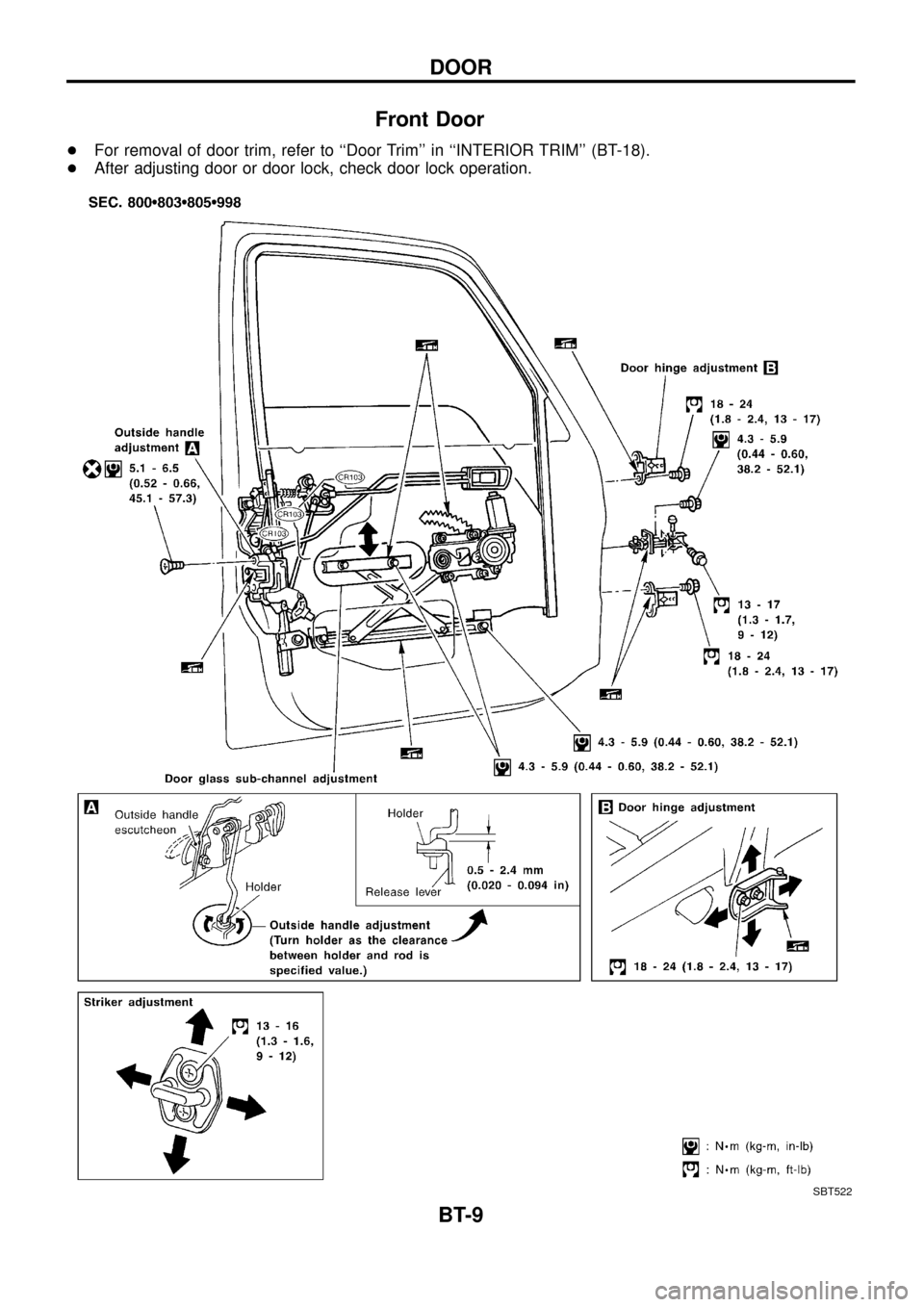
Front Door
+For removal of door trim, refer to ``Door Trim'' in ``INTERIOR TRIM'' (BT-18).
+After adjusting door or door lock, check door lock operation.
SBT522
DOOR
BT-9