NISSAN PATROL 2000 Electronic Owner's Manual
Manufacturer: NISSAN, Model Year: 2000, Model line: PATROL, Model: NISSAN PATROL 2000Pages: 1033, PDF Size: 30.71 MB
Page 21 of 1033
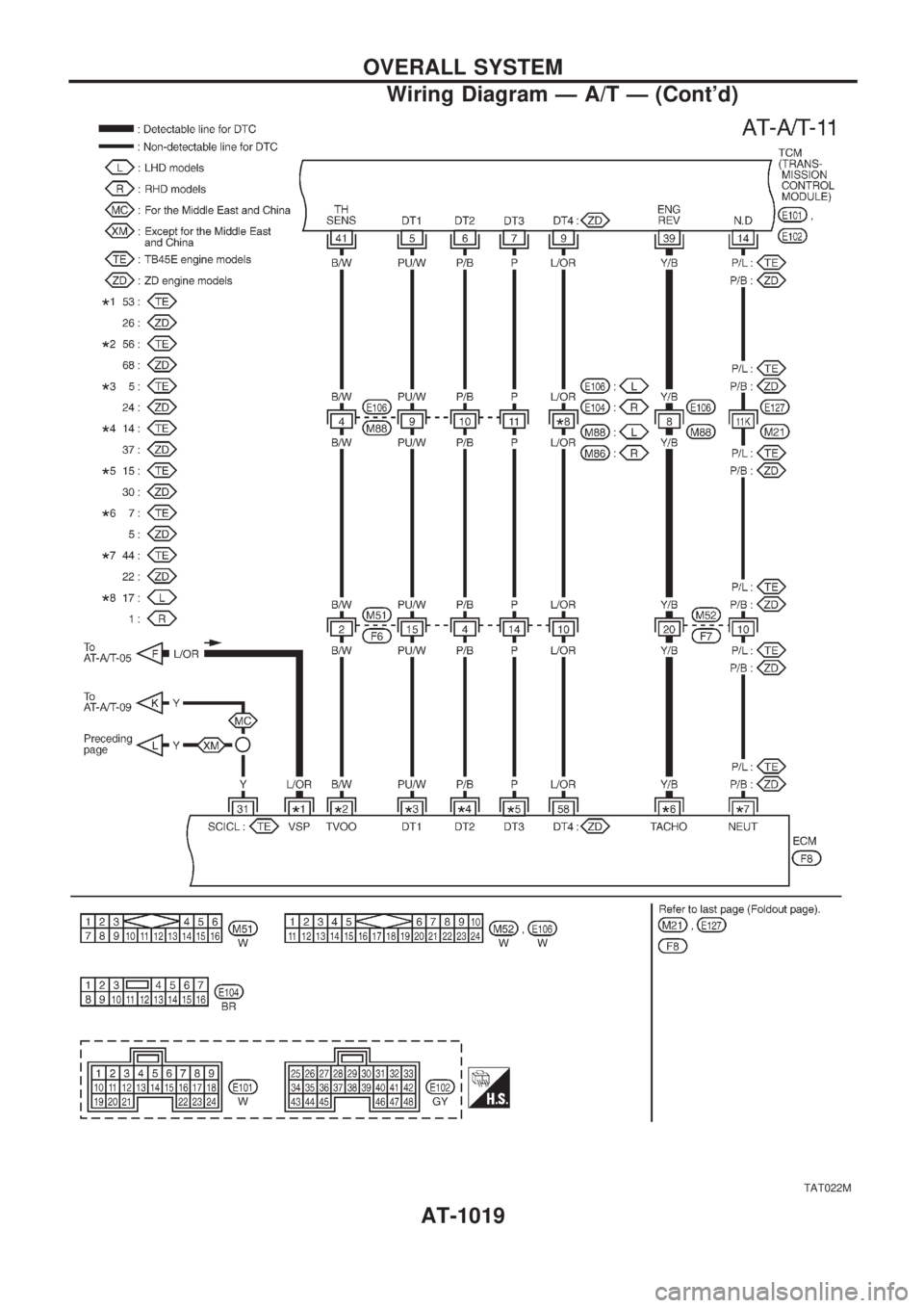
TAT022M
OVERALL SYSTEM
Wiring Diagram Ð A/T Ð (Cont'd)
AT-1019
Page 22 of 1033
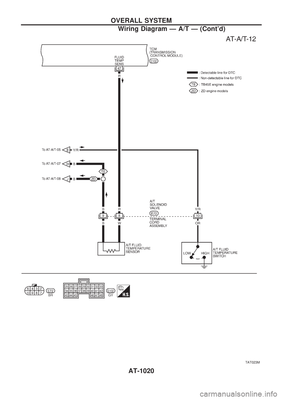
TAT023M
OVERALL SYSTEM
Wiring Diagram Ð A/T Ð (Cont'd)
AT-1020
Page 23 of 1033
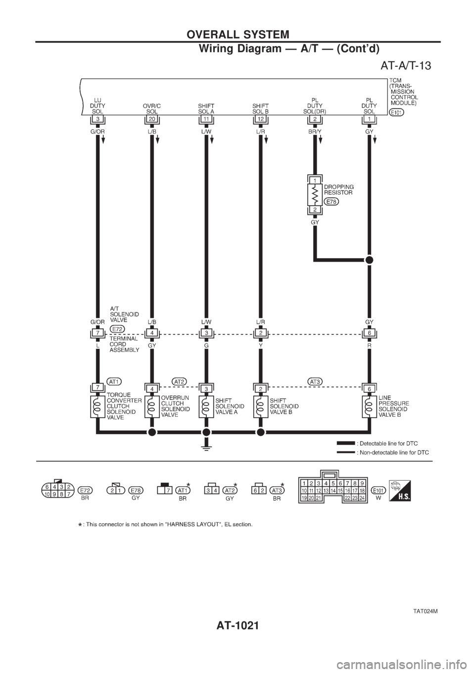
TAT024M
OVERALL SYSTEM
Wiring Diagram Ð A/T Ð (Cont'd)
AT-1021
Page 24 of 1033
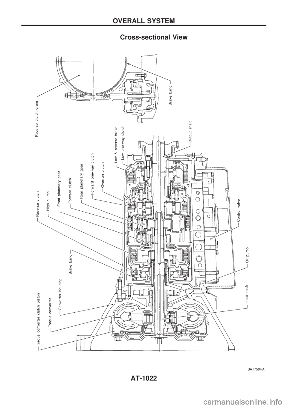
Cross-sectional View
SAT750HA
OVERALL SYSTEM
AT-1022
Page 25 of 1033
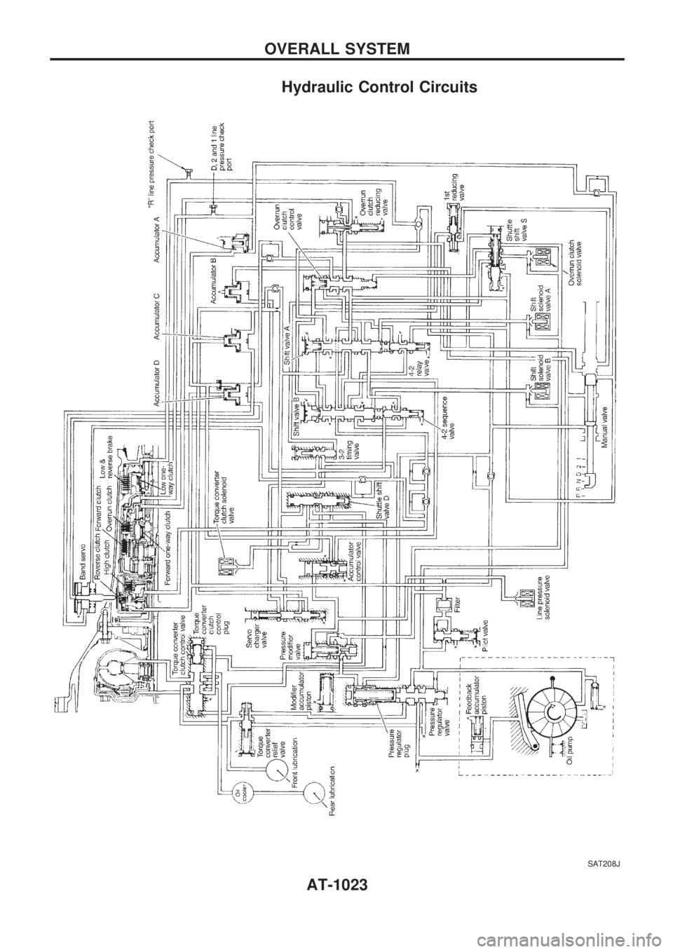
Hydraulic Control Circuits
SAT208J
OVERALL SYSTEM
AT-1023
Page 26 of 1033
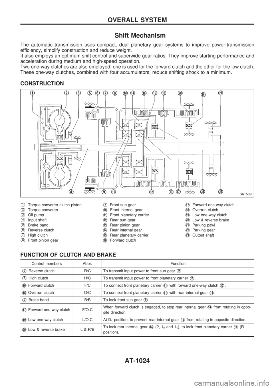
Shift Mechanism
The automatic transmission uses compact, dual planetary gear systems to improve power-transmission
efficiency, simplify construction and reduce weight.
It also employs an optimum shift control and superwide gear ratios. They improve starting performance and
acceleration during medium and high-speed operation.
Two one-way clutches are also employed: one is used for the forward clutch and the other for the low clutch.
These one-way clutches, combined with four accumulators, reduce shifting shock to a minimum.
CONSTRUCTION
V1Torque converter clutch piston
V2Torque converter
V3Oil pump
V4Input shaft
V5Brake band
V6Reverse clutch
V7High clutch
V8Front pinion gear
V9Front sun gear
V10Front internal gear
V11Front planetary carrier
V12Rear sun gear
V13Rear pinion gear
V14Rear internal gear
V15Rear planetary carrier
V16Forward clutch
V17Forward one-way clutch
V18Overrun clutch
V19Low one-way clutch
V20Low & reverse brake
V21Parking pawl
V22Parking gear
V23Output shaft
FUNCTION OF CLUTCH AND BRAKE
Control members Abbr. Function
V6Reverse clutch R/C To transmit input power to front sun gearV9.
V7High clutch H/C To transmit input power to front planetary carrierV11.
V16Forward clutch F/C To connect front planetary carrierV11with forward one-way clutchV17.
V18Overrun clutch O/C To connect front planetary carrierV11with rear internal gearV14.
V5Brake band B/B To lock front sun gearV9.
V17Forward one-way clutch F/O.CWhen forward clutch is engaged, to stop rear internal gearV14from rotating in oppo-
site direction.
V19Low one-way clutch L/O.C At D1position, to prevent rear internal gearV14from rotating in opposite direction.
V20Low & reverse brake L & R/BTo lock rear internal gearV14(2, 12and 11), to lock front planetary carrierV11(R
position).
SAT509I
OVERALL SYSTEM
AT-1024
Page 27 of 1033
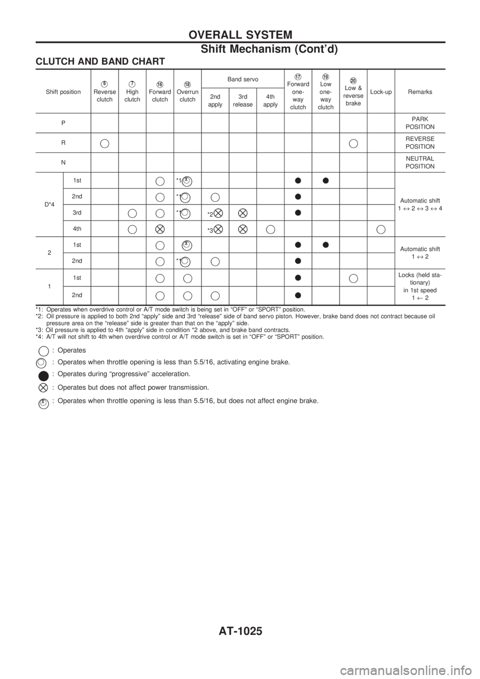
CLUTCH AND BAND CHART
Shift positionV6
Reverse
clutchV7
High
clutchV16Forward
clutchV18Overrun
clutchBand servo
V17Forward
one-
way
clutchV19Low
one-
way
clutchV20Low &
reverse
brakeLock-up Remarks
2nd
apply3rd
release4th
apply
PPARK
POSITION
R
jjREVERSE
POSITION
NNEUTRAL
POSITION
D*41st
j*1jVX++
Automatic shift
1«2«3«4 2ndj*1jVj+
3rdjj*1jV*2^^+
4thj^*3^^jj
21stjjVX++Automatic shift
1«2
2nd
j*1jVj+
11stjj+jLocks (held sta-
tionary)
in 1st speed
1¬2 2nd
jjj+
*1: Operates when overdrive control or A/T mode switch is being set in ªOFFº or ªSPORTº position.
*2: Oil pressure is applied to both 2nd ªapplyº side and 3rd ªreleaseº side of band servo piston. However, brake band does not contract because oil
pressure area on the ªreleaseº side is greater than that on the ªapplyº side.
*3: Oil pressure is applied to 4th ªapplyº side in condition *2 above, and brake band contracts.
*4: A/T will not shift to 4th when overdrive control or A/T mode switch is set in ªOFFº or ªSPORTº position.
j: Operates
: Operates when throttle opening is less than 5.5/16, activating engine brake.
*: Operates during ªprogressiveº acceleration.
^: Operates but does not affect power transmission.
jVX: Operates when throttle opening is less than 5.5/16, but does not affect engine brake.
jV
OVERALL SYSTEM
Shift Mechanism (Cont'd)
AT-1025
Page 28 of 1033
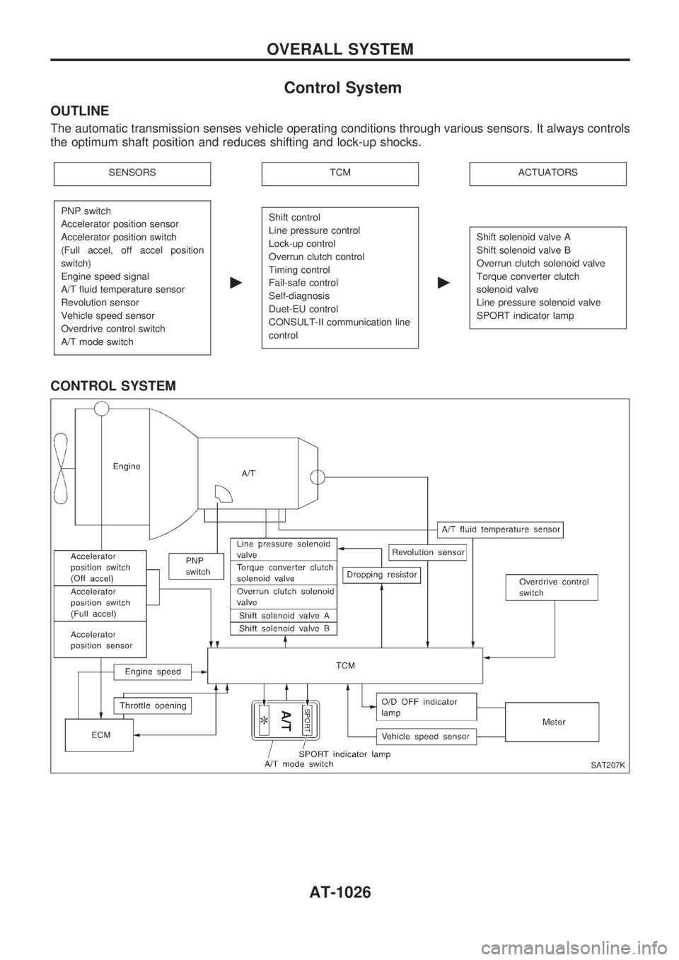
Control System
OUTLINE
The automatic transmission senses vehicle operating conditions through various sensors. It always controls
the optimum shaft position and reduces shifting and lock-up shocks.
SENSORSTCMACTUATORS
PNP switch
Accelerator position sensor
Accelerator position switch
(Full accel, off accel position
switch)
Engine speed signal
A/T fluid temperature sensor
Revolution sensor
Vehicle speed sensor
Overdrive control switch
A/T mode switch
c
Shift control
Line pressure control
Lock-up control
Overrun clutch control
Timing control
Fail-safe control
Self-diagnosis
Duet-EU control
CONSULT-II communication line
control
c
Shift solenoid valve A
Shift solenoid valve B
Overrun clutch solenoid valve
Torque converter clutch
solenoid valve
Line pressure solenoid valve
SPORT indicator lamp
CONTROL SYSTEM
SAT207K
OVERALL SYSTEM
AT-1026
Page 29 of 1033
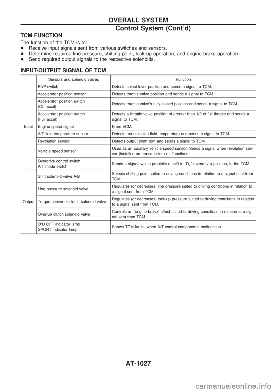
TCM FUNCTION
The function of the TCM is to:
+Receive input signals sent from various switches and sensors.
+Determine required line pressure, shifting point, lock-up operation, and engine brake operation.
+Send required output signals to the respective solenoids.
INPUT/OUTPUT SIGNAL OF TCM
Sensors and solenoid valves Function
InputPNP switch Detects select lever position and sends a signal to TCM.
Accelerator position sensor Detects throttle valve position and sends a signal to TCM.
Accelerator position switch
(Off accel)Detects throttle valve's fully-closed position and sends a signal to TCM.
Accelerator position switch
(Full accel)Detects a throttle valve position of greater than 1/2 of full throttle and sends a
signal to TCM.
Engine speed signal From ECM.
A/T fluid temperature sensor Detects transmission fluid temperature and sends a signal to TCM.
Revolution sensor Detects output shaft rpm and sends a signal to TCM.
Vehicle speed sensorUsed as an auxiliary vehicle speed sensor. Sends a signal when revolution sen-
sor (installed on transmission) malfunctions.
Overdrive control switch
A/T mode switchSends a signal, which prohibits a shift to ªD
4º (overdrive) position, to the TCM.
OutputShift solenoid valve A/BSelects shifting point suited to driving conditions in relation to a signal sent from
TCM.
Line pressure solenoid valveRegulates (or decreases) line pressure suited to driving conditions in relation to
a signal sent from TCM.
Torque converter clutch solenoid valveRegulates (or decreases) lock-up pressure suited to driving conditions in relation
to a signal sent from TCM.
Overrun clutch solenoid valveControls an ªengine brakeº effect suited to driving conditions in relation to a sig-
nal sent from TCM.
O/D OFF indicator lamp
SPORT indicator lampShows TCM faults, when A/T control components malfunction.
OVERALL SYSTEM
Control System (Cont'd)
AT-1027
Page 30 of 1033
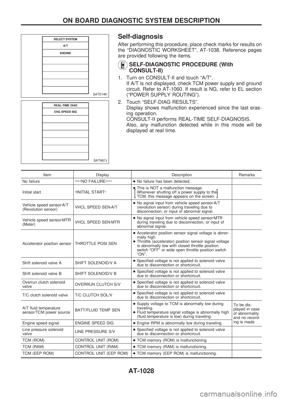
Self-diagnosis
After performing this procedure, place check marks for results on
the ªDIAGNOSTIC WORKSHEETº, AT-1038. Reference pages
are provided following the items.
SELF-DIAGNOSTIC PROCEDURE (With
CONSULT-II)
1. Turn on CONSULT-II and touch ªA/Tº.
If A/T is not displayed, check TCM power supply and ground
circuit. Refer to AT-1060. If result is NG, refer to EL section
(ªPOWER SUPPLY ROUTINGº).
2. Touch ªSELF-DIAG RESULTSº.
Display shows malfunction experienced since the last eras-
ing operation.
CONSULT-II performs REAL-TIME SELF-DIAGNOSIS.
Also, any malfunction detected while in this mode will be
displayed at real time.
Item Display Description Remarks
No failure
****NO FAILURE
****+No failure has been detected.
Initial start
*INITIAL START
*+This is NOT a malfunction message.
Whenever shutting off a power supply to the
TCM, this message appears on the screen.
[]
Vehicle speed sensorzA/T
(Revolution sensor)VHCL SPEED SENzA/T+No signal input from vehicle speed sensorzA/T
(revolution sensor) during traveling due to
disconnection, or input of abnormal signal.
Vehicle speed sensorzMTR
(Meter)VHCL SPEED SENzMTR+No signal input from vehicle speed sensorzMTR
during traveling due to disconnection, or input of
abnormal signal.
Accelerator position sensor THROTTLE POSI SEN+Accelerator position sensor signal voltage is abnor-
mally high.
+Throttle (accelerator) position sensor signal voltage
is abnormally low with closed throttle position
switch ªOFFº or wide open throttle position switch
ªONº.
Shift solenoid valve A SHIFT SOLENOID/V A+Specified voltage is not applied to solenoid valve
due to disconnection or shortcircuit.
Shift solenoid valve B SHIFT SOLENOID/V B+Specified voltage is not applied to solenoid valve
due to disconnection or shortcircuit.
Overrun clutch solenoid
valveOVERRUN CLUTCH S/V+Specified voltage is not applied to solenoid valve
due to disconnection or shortcircuit.
T/C clutch solenoid valve T/C CLUTCH SOL/V+Specified voltage is not applied to solenoid valve
due to disconnection or shortcircuit.
A/T fluid temperature
sensor/TCM power sourceBATT/FLUID TEMP SEN+Supply voltage to TCM is abnormally low during
traveling.
+Fluid temperature signal voltage is abnormally high
(fluid temperature is low) during traveling.To be dis-
played in case
of abnormality
and no record-
ing is made
Engine speed signal ENGINE SPEED SIG+Engine RPM is abnormally low during traveling.
Line pressure solenoid
valveLINE PRESSURE S/V+Specified voltage is not applied to solenoid valve
due to disconnection or shortcircuit.
TCM (ROM) CONTROL UNIT (ROM)+TCM memory (ROM) is malfunctioning.
TCM (RAM) CONTROL UNIT (RAM)+TCM memory (RAM) is malfunctioning.
TCM (EEP ROM) CONTROL UNIT (EEP ROM)+TCM memory (EEP ROM) is malfunctioning.
SAT014K
SAT987J
ON BOARD DIAGNOSTIC SYSTEM DESCRIPTION
AT-1028