air condition NISSAN PATROL 2000 Electronic Owner's Manual
[x] Cancel search | Manufacturer: NISSAN, Model Year: 2000, Model line: PATROL, Model: NISSAN PATROL 2000Pages: 1033, PDF Size: 30.71 MB
Page 252 of 1033
Fuel Injection Control System
DESCRIPTION
System description
Three types of fuel injection control are provided to accommodate engine operating conditions; normal
control, idle control and start control. The ECM determines the appropriate fuel injection control. Under each
control, the amount of fuel injected is compensated to improve engine performance.
Pulse signals are exchanged between ECM and electronic control fuel injection pump (control unit is built-
in). The fuel injection pump control unit performs duty control on the spill valve (built into the fuel injection
pump) according to the input signals to compensate the amount of fuel injected to the preset value.
Start control
Input/output signal chart
Sensor Input Signal to ECM ECM Function Actuator
Engine coolant temperature sensor Engine coolant temperature
Fuel injection con-
trol (start control)Electronic control fuel injec-
tion pump Crankshaft position sensor (TDC) Engine speed
Ignition switch Start signal
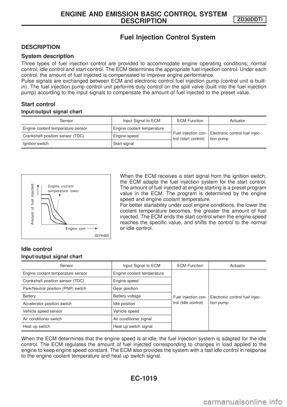
When the ECM receives a start signal from the ignition switch,
the ECM adapts the fuel injection system for the start control.
The amount of fuel injected at engine starting is a preset program
value in the ECM. The program is determined by the engine
speed and engine coolant temperature.
For better startability under cool engine conditions, the lower the
coolant temperature becomes, the greater the amount of fuel
injected. The ECM ends the start control when the engine speed
reaches the specific value, and shifts the control to the normal
or idle control.
Idle control
Input/output signal chart
Sensor Input Signal to ECM ECM Function Actuator
Engine coolant temperature sensor Engine coolant temperature
Fuel injection con-
trol (Idle control)Electronic control fuel injec-
tion pump Crankshaft position sensor (TDC) Engine speed
Park/Neutral position (PNP) switch Gear position
Battery Battery voltage
Accelerator position switch Idle position
Vehicle speed sensor Vehicle speed
Air conditioner switch Air conditioner signal
Heat up switch Heat up switch signal
When the ECM determines that the engine speed is at idle, the fuel injection system is adapted for the idle
control. The ECM regulates the amount of fuel injected corresponding to changes in load applied to the
engine to keep engine speed constant. The ECM also provides the system with a fast idle control in response
to the engine coolant temperature and heat up switch signal.
SEF648S
ENGINE AND EMISSION BASIC CONTROL SYSTEM
DESCRIPTIONZD30DDTi
EC-1019
Page 253 of 1033
Normal control
Input/output signal chart
Sensor Input Signal to ECM ECM Function Actuator
Crankshaft position sensor (TDC) Engine speed
Fuel injection con-
trol (Normal con-
trol)Electronic control fuel injec-
tion pump Accelerator position sensor Accelerator position
Vehicle speed sensor Vehicle speed
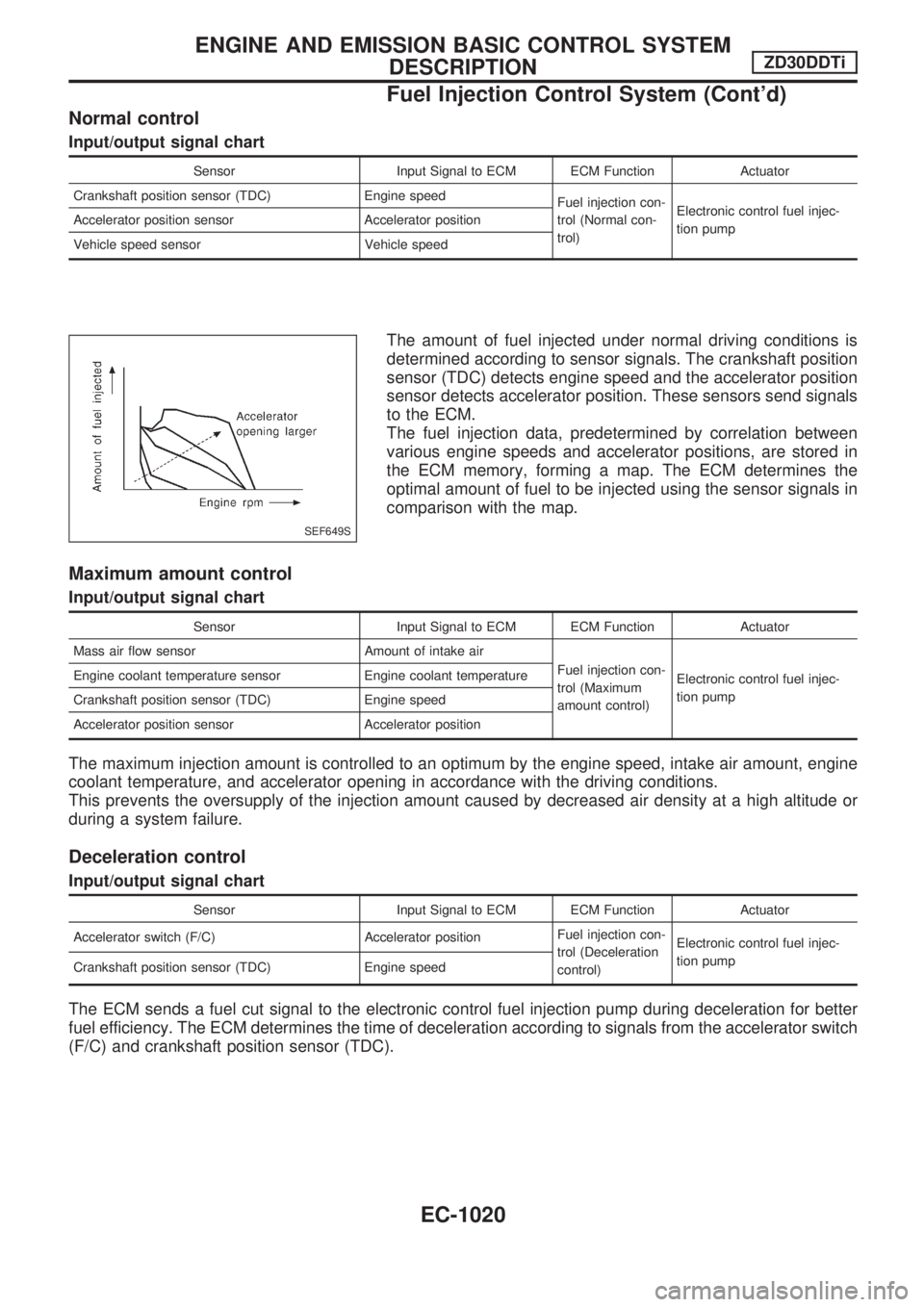
The amount of fuel injected under normal driving conditions is
determined according to sensor signals. The crankshaft position
sensor (TDC) detects engine speed and the accelerator position
sensor detects accelerator position. These sensors send signals
to the ECM.
The fuel injection data, predetermined by correlation between
various engine speeds and accelerator positions, are stored in
the ECM memory, forming a map. The ECM determines the
optimal amount of fuel to be injected using the sensor signals in
comparison with the map.
Maximum amount control
Input/output signal chart
Sensor Input Signal to ECM ECM Function Actuator
Mass air flow sensor Amount of intake air
Fuel injection con-
trol (Maximum
amount control)Electronic control fuel injec-
tion pump Engine coolant temperature sensor Engine coolant temperature
Crankshaft position sensor (TDC) Engine speed
Accelerator position sensor Accelerator position
The maximum injection amount is controlled to an optimum by the engine speed, intake air amount, engine
coolant temperature, and accelerator opening in accordance with the driving conditions.
This prevents the oversupply of the injection amount caused by decreased air density at a high altitude or
during a system failure.
Deceleration control
Input/output signal chart
Sensor Input Signal to ECM ECM Function Actuator
Accelerator switch (F/C) Accelerator positionFuel injection con-
trol (Deceleration
control)Electronic control fuel injec-
tion pump
Crankshaft position sensor (TDC) Engine speed
The ECM sends a fuel cut signal to the electronic control fuel injection pump during deceleration for better
fuel efficiency. The ECM determines the time of deceleration according to signals from the accelerator switch
(F/C) and crankshaft position sensor (TDC).
SEF649S
ENGINE AND EMISSION BASIC CONTROL SYSTEM
DESCRIPTIONZD30DDTi
Fuel Injection Control System (Cont'd)
EC-1020
Page 254 of 1033
Fuel Injection Timing Control System
DESCRIPTION
The target fuel injection timing in accordance with the engine speed and the fuel injection amount are
recorded as a map in the ECM beforehand. The ECM and the injection pump control unit exchange signals
and perform feedback control for optimum injection timing in accordance with the map.
Air Conditioning Cut Control
DESCRIPTION
Input/output signal chart
Sensor Input Signal to ECM ECM Function Actuator
Air conditioner switch Air conditioner ªONº signal
Air conditioner cut
controlAir conditioner relay Accelerator position sensorAccelerator valve opening
angle
Vehicle speed sensor Vehicle speed
Engine coolant temperature sensor Engine coolant temperature
System description
This system improves acceleration when the air conditioner is used.
When the accelerator pedal is fully depressed, the air conditioner is turned off for a few seconds.
When engine coolant temperature becomes excessively high, the air conditioner is turned off. This contin-
ues until the engine coolant temperature returns to normal.
Fuel Cut Control (at no load & high engine
speed)
DESCRIPTION
Input/output signal chart
Sensor Input Signal to ECM ECM Function Actuator
Vehicle speed sensor Vehicle speed
Fuel cut controlElectronic control fuel injec-
tion pump Park/Neutral position (PNP) switch Neutral position
Accelerator position switch or Accelerator
switch (F/C)Accelerator position
Engine coolant temperature sensor Engine coolant temperature
Crankshaft position sensor (TDC) Engine speed
If the engine speed is above 2,700 rpm with no load (for example, in neutral and engine speed over 2,700
rpm) fuel will be cut off after some time. The exact time when the fuel is cut off varies based on engine speed.
Fuel cut will operate until the engine speed reaches 1,500 rpm, then fuel cut is cancelled.
NOTE:
This function is different from deceleration control listed under ªFuel Injection Control Systemº,
EC-1019.
ENGINE AND EMISSION BASIC CONTROL SYSTEM
DESCRIPTIONZD30DDTi
EC-1021
Page 272 of 1033
ENGINE CONTROL COMPONENT PARTS/CONTROL
SYSTEMS APPLICATION
ItemDIAGNOSTIC TEST MODE
SELF-DIAG
RESULTSDATA MONI-
TORACTIVE
TEST
ENGINE CONTROL COMPONENT PARTS
INPUTEngine coolant temperature sensor X X
Vehicle speed sensor X X
Accelerator position sensor X X X
Accelerator position switch X X
Accelerator switch (F/C) X X
Crankshaft position sensor (TDC) X X
Ignition switch (start signal) X
Park/Neutral position (PNP) switch X
Battery voltage X
Air conditioner switch X
Mass air flow sensor X X
Stop lamp switch X X
Heat up switch X
Charge air pressure sensor X
OUTPUTGlow relayXX
EGR volume control valve X X X
Cooling fan relay X X X
Air conditioner relay X
Variable nozzle turbocharger control solenoid valve X
Swirl control valve control solenoid valve X X
Exhaust gas control valve control solenoid valve X
X: Applicable
SELF-DIAGNOSTIC MODE
Regarding items detected in ªSELF-DIAG RESULTSº mode,
refer to ªTROUBLE DIAGNOSIS Ð INDEXº, EC-1006.
DATA MONITOR MODE
Monitored item
[Unit]ECM
input
signalsMain
signalsDescription Remarks
CKPSzRPM (TDC)
[rpm]jj+The engine speed computed from the
crankshaft position sensor (TDC) signal
is displayed.
CMPSzRPMzPUMP
[rpm]jj+The engine speed computed from the
pulse signal sent from electronic control
fuel injection pump is displayed.
COOLAN TEMP/S
[ÉC] or [ÉF]
jj+The engine coolant temperature (deter-
mined by the signal voltage of the
engine coolant temperature sensor) is
displayed.+When the engine coolant temperature
sensor is open or short-circuited, ECM
enters fail-safe mode. The engine cool-
ant temperature determined by the ECM
is displayed.
ON BOARD DIAGNOSTIC SYSTEM DESCRIPTIONZD30DDTi
CONSULT-II (Cont'd)
EC-1039
Page 273 of 1033
![NISSAN PATROL 2000 Electronic Owners Manual Monitored item
[Unit]ECM
input
signalsMain
signalsDescription Remarks
VHCL SPEED SE
[km/h] or [mph]jj+The vehicle speed computed from the
vehicle speed sensor signal is displayed.
FUEL TEMP SEN
[ÉC]](/img/5/57367/w960_57367-272.png "NISSAN PATROL 2000 Electronic Owners Manual Monitored item
[Unit]ECM
input
signalsMain
signalsDescription Remarks
VHCL SPEED SE
[km/h] or [mph]jj+The vehicle speed computed from the
vehicle speed sensor signal is displayed.
FUEL TEMP SEN
[ÉC]")
Monitored item
[Unit]ECM
input
signalsMain
signalsDescription Remarks
VHCL SPEED SE
[km/h] or [mph]jj+The vehicle speed computed from the
vehicle speed sensor signal is displayed.
FUEL TEMP SEN
[ÉC] or [ÉF]jj+The fuel temperature (sent from elec-
tronic control fuel injection pump) is dis-
played.
ACCEL POS SEN [V]
jj+The accelerator position sensor signal
voltage is displayed.
FULL ACCEL SW
[ON/OFF]jj+Indicates [ON/OFF] condition from the
accelerator position switch signal.
ACCEL SW (FC)
[OPEN/CLOSE]jj+Indicates [OPEN/CLOSE] condition from
the accelerator switch (FC) signal.
OFF ACCEL SW
[ON/OFF]jj+Indicates [ON/OFF] condition from the
accelerator position switch signal.
SPILL/V [ÉCA]
j+The control position of spill valve (sent
from electronic control fuel injection
pump) is displayed.
BATTERY VOLT [V]
jj+The power supply voltage of ECM is dis-
played.
P/N POSI SW
[ON/OFF]jj+Indicates [ON/OFF] condition from the
park/neutral position switch signal.
START SIGNAL
[ON/OFF]jj+Indicates [ON/OFF] condition from the
starter signal.+After starting the engine, [OFF] is dis-
played regardless of the starter signal.
AIR COND SIG
[ON/OFF]jj+Indicates [ON/OFF] condition of the air
conditioner switch as determined by the
air conditioner signal.
BRAKE SW [ON/OFF]
jj+Indicates [ON/OFF] condition from the
stop lamp switch signal.
IGN SW
[ON/OFF]jj+Indicates [ON/OFF] condition from igni-
tion switch signal.
WARM UP SW
[ON/OFF]j+Indicates [ON/OFF] condition from the
heat up switch signal.
MAS AIR/FL SE [V]
jj+The signal voltage of the mass air flow
sensor is displayed.+When the engine is stopped, a certain
value is indicated.
DECELER F/CUT
[ON/OFF]j+The [ON/OFF] condition from decelera-
tion fuel cut signal (sent from electronic
control fuel injection pump) is displayed.
INJ TIMG C/V [%]
j+The duty ratio of fuel injection timing
control valve (sent from electronic con-
trol fuel injection pump) is displayed.
AIR COND RLY
[ON/OFF]j+Indicates the control condition of the air
conditioner relay (determined by ECM
according to the input signals).
GLOW RLY [ON/OFF]
j+The glow relay control condition (deter-
mined by ECM according to the input
signal) is displayed.
ON BOARD DIAGNOSTIC SYSTEM DESCRIPTIONZD30DDTi
CONSULT-II (Cont'd)
EC-1040
Page 281 of 1033
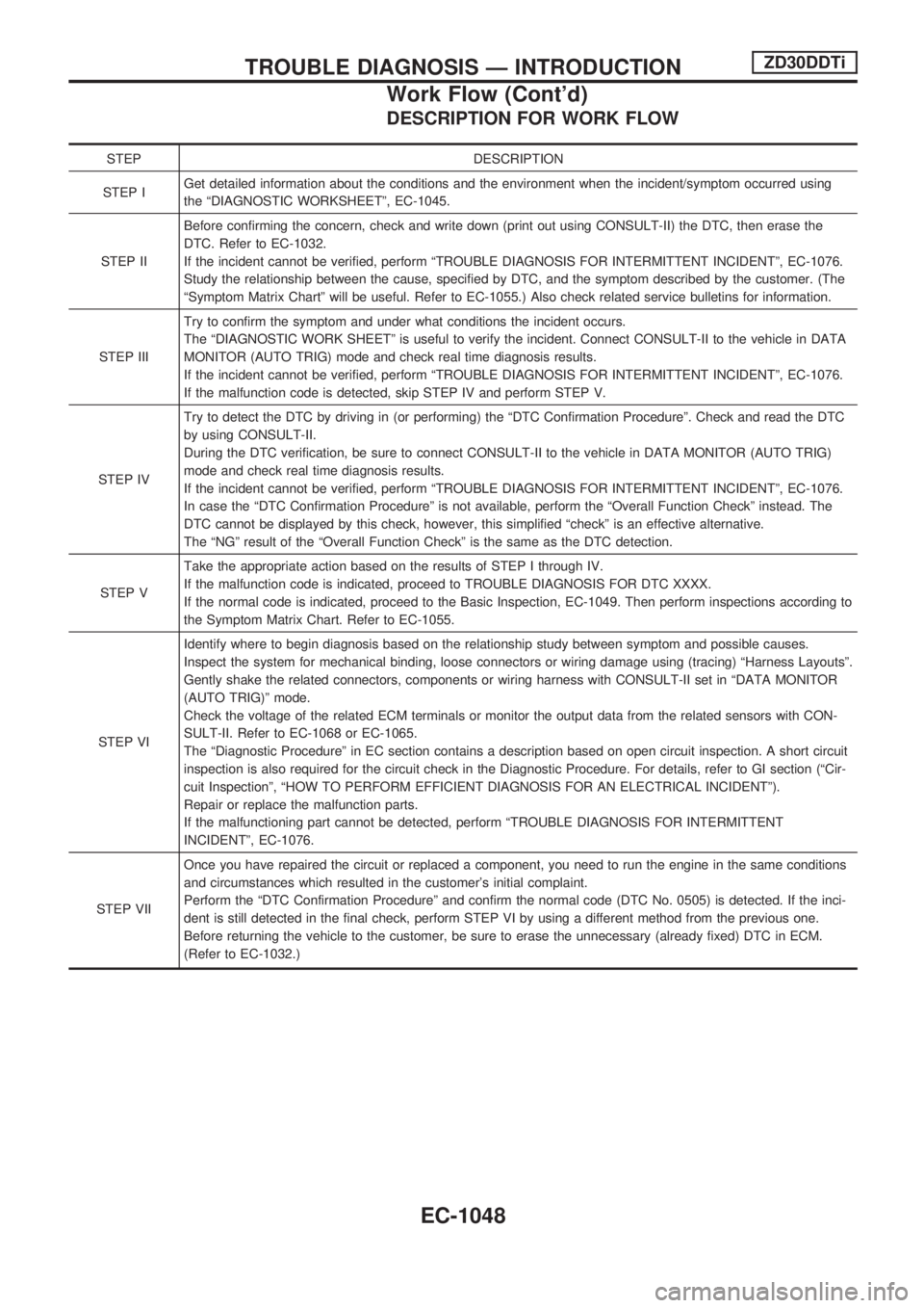
DESCRIPTION FOR WORK FLOW
STEP DESCRIPTION
STEP IGet detailed information about the conditions and the environment when the incident/symptom occurred using
the ªDIAGNOSTIC WORKSHEETº, EC-1045.
STEP IIBefore confirming the concern, check and write down (print out using CONSULT-II) the DTC, then erase the
DTC. Refer to EC-1032.
If the incident cannot be verified, perform ªTROUBLE DIAGNOSIS FOR INTERMITTENT INCIDENTº, EC-1076.
Study the relationship between the cause, specified by DTC, and the symptom described by the customer. (The
ªSymptom Matrix Chartº will be useful. Refer to EC-1055.) Also check related service bulletins for information.
STEP IIITry to confirm the symptom and under what conditions the incident occurs.
The ªDIAGNOSTIC WORK SHEETº is useful to verify the incident. Connect CONSULT-II to the vehicle in DATA
MONITOR (AUTO TRIG) mode and check real time diagnosis results.
If the incident cannot be verified, perform ªTROUBLE DIAGNOSIS FOR INTERMITTENT INCIDENTº, EC-1076.
If the malfunction code is detected, skip STEP IV and perform STEP V.
STEP IVTry to detect the DTC by driving in (or performing) the ªDTC Confirmation Procedureº. Check and read the DTC
by using CONSULT-II.
During the DTC verification, be sure to connect CONSULT-II to the vehicle in DATA MONITOR (AUTO TRIG)
mode and check real time diagnosis results.
If the incident cannot be verified, perform ªTROUBLE DIAGNOSIS FOR INTERMITTENT INCIDENTº, EC-1076.
In case the ªDTC Confirmation Procedureº is not available, perform the ªOverall Function Checkº instead. The
DTC cannot be displayed by this check, however, this simplified ªcheckº is an effective alternative.
The ªNGº result of the ªOverall Function Checkº is the same as the DTC detection.
STEP VTake the appropriate action based on the results of STEP I through IV.
If the malfunction code is indicated, proceed to TROUBLE DIAGNOSIS FOR DTC XXXX.
If the normal code is indicated, proceed to the Basic Inspection, EC-1049. Then perform inspections according to
the Symptom Matrix Chart. Refer to EC-1055.
STEP VIIdentify where to begin diagnosis based on the relationship study between symptom and possible causes.
Inspect the system for mechanical binding, loose connectors or wiring damage using (tracing) ªHarness Layoutsº.
Gently shake the related connectors, components or wiring harness with CONSULT-II set in ªDATA MONITOR
(AUTO TRIG)º mode.
Check the voltage of the related ECM terminals or monitor the output data from the related sensors with CON-
SULT-II. Refer to EC-1068 or EC-1065.
The ªDiagnostic Procedureº in EC section contains a description based on open circuit inspection. A short circuit
inspection is also required for the circuit check in the Diagnostic Procedure. For details, refer to GI section (ªCir-
cuit Inspectionº, ªHOW TO PERFORM EFFICIENT DIAGNOSIS FOR AN ELECTRICAL INCIDENTº).
Repair or replace the malfunction parts.
If the malfunctioning part cannot be detected, perform ªTROUBLE DIAGNOSIS FOR INTERMITTENT
INCIDENTº, EC-1076.
STEP VIIOnce you have repaired the circuit or replaced a component, you need to run the engine in the same conditions
and circumstances which resulted in the customer's initial complaint.
Perform the ªDTC Confirmation Procedureº and confirm the normal code (DTC No. 0505) is detected. If the inci-
dent is still detected in the final check, perform STEP VI by using a different method from the previous one.
Before returning the vehicle to the customer, be sure to erase the unnecessary (already fixed) DTC in ECM.
(Refer to EC-1032.)
TROUBLE DIAGNOSIS Ð INTRODUCTIONZD30DDTi
Work Flow (Cont'd)
EC-1048
Page 282 of 1033
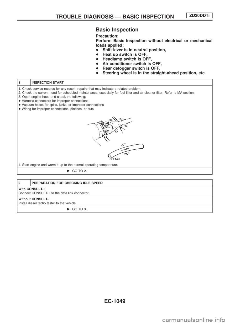
Basic Inspection
Precaution:
Perform Basic Inspection without electrical or mechanical
loads applied;
+Shift lever is in neutral position,
+Heat up switch is OFF,
+Headlamp switch is OFF,
+Air conditioner switch is OFF,
+Rear defogger switch is OFF,
+Steering wheel is in the straight-ahead position, etc.
1 INSPECTION START
1. Check service records for any recent repairs that may indicate a related problem.
2. Check the current need for scheduled maintenance, especially for fuel filter and air cleaner filter. Refer to MA section.
3. Open engine hood and check the following:
+Harness connectors for improper connections
+Vacuum hoses for splits, kinks, or improper connections
+Wiring for improper connections, pinches, or cuts
SEF142I
4. Start engine and warm it up to the normal operating temperature.
cGO TO 2.
2 PREPARATION FOR CHECKING IDLE SPEED
With CONSULT-II
Connect CONSULT-II to the data link connector.
Without CONSULT-II
Install diesel tacho tester to the vehicle.
cGO TO 3.
TROUBLE DIAGNOSIS Ð BASIC INSPECTIONZD30DDTi
EC-1049
Page 296 of 1033
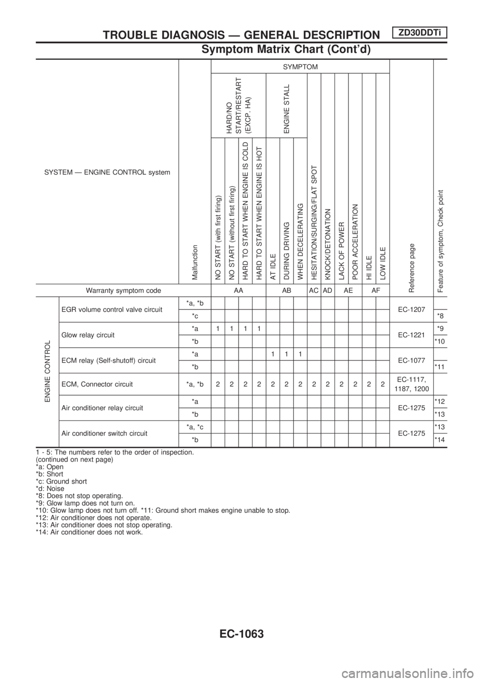
SYSTEM Ð ENGINE CONTROL system
Malfunction
SYMPTOM
Reference page
Feature of symptom, Check pointHARD/NO
START/RESTART
(EXCP. HA)
ENGINE STALL
HESITATION/SURGING/FLAT SPOT
KNOCK/DETONATION
LACK OF POWER
POOR ACCELERATION
HI IDLE
LOW IDLE NO START (with first firing)
NO START (without first firing)
HARD TO START WHEN ENGINE IS COLD
HARD TO START WHEN ENGINE IS HOT
AT IDLE
DURING DRIVING
WHEN DECELERATINGWarranty symptom code AA AB AC AD AE AF
ENGINE CONTROL
EGR volume control valve circuit*a, *b
EC-1207
*c*8
Glow relay circuit*a 1111
EC-1221*9
*b*10
ECM relay (Self-shutoff) circuit*a 111
EC-1077
*b*11
ECM, Connector circuit *a, *b2222222222222EC-1117,
1187, 1200
Air conditioner relay circuit*a
EC-1275*12
*b*13
Air conditioner switch circuit*a, *c
EC-1275*13
*b*14
1 - 5: The numbers refer to the order of inspection.
(continued on next page)
*a: Open
*b: Short
*c: Ground short
*d: Noise
*8: Does not stop operating.
*9: Glow lamp does not turn on.
*10: Glow lamp does not turn off. *11: Ground short makes engine unable to stop.
*12: Air conditioner does not operate.
*13: Air conditioner does not stop operating.
*14: Air conditioner does not work.
TROUBLE DIAGNOSIS Ð GENERAL DESCRIPTIONZD30DDTi
Symptom Matrix Chart (Cont'd)
EC-1063
Page 297 of 1033
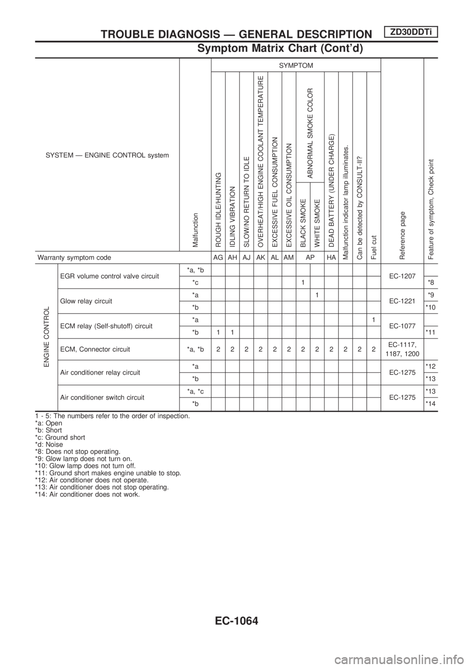
SYSTEM Ð ENGINE CONTROL system
Malfunction
SYMPTOM
Reference page
Feature of symptom, Check pointROUGH IDLE/HUNTING
IDLING VIBRATION
SLOW/NO RETURN TO IDLE
OVERHEAT/HIGH ENGINE COOLANT TEMPERATURE
EXCESSIVE FUEL CONSUMPTION
EXCESSIVE OIL CONSUMPTION
ABNORMAL SMOKE COLOR
DEAD BATTERY (UNDER CHARGE)
Malfunction indicator lamp illuminates.
Can be detected by CONSULT-II?
Fuel cutBLACK SMOKE
WHITE SMOKEWarranty symptom code AG AH AJ AK AL AM AP HA
ENGINE CONTROL
EGR volume control valve circuit*a, *b
EC-1207
*c 1 *8
Glow relay circuit*a 1
EC-1221*9
*b*10
ECM relay (Self-shutoff) circuit*a 1
EC-1077
*b 1 1 *11
ECM, Connector circuit *a, *b222222222222EC-1117,
1187, 1200
Air conditioner relay circuit*a
EC-1275*12
*b*13
Air conditioner switch circuit*a, *c
EC-1275*13
*b*14
1 - 5: The numbers refer to the order of inspection.
*a: Open
*b: Short
*c: Ground short
*d: Noise
*8: Does not stop operating.
*9: Glow lamp does not turn on.
*10: Glow lamp does not turn off.
*11: Ground short makes engine unable to stop.
*12: Air conditioner does not operate.
*13: Air conditioner does not stop operating.
*14: Air conditioner does not work.
TROUBLE DIAGNOSIS Ð GENERAL DESCRIPTIONZD30DDTi
Symptom Matrix Chart (Cont'd)
EC-1064
Page 298 of 1033
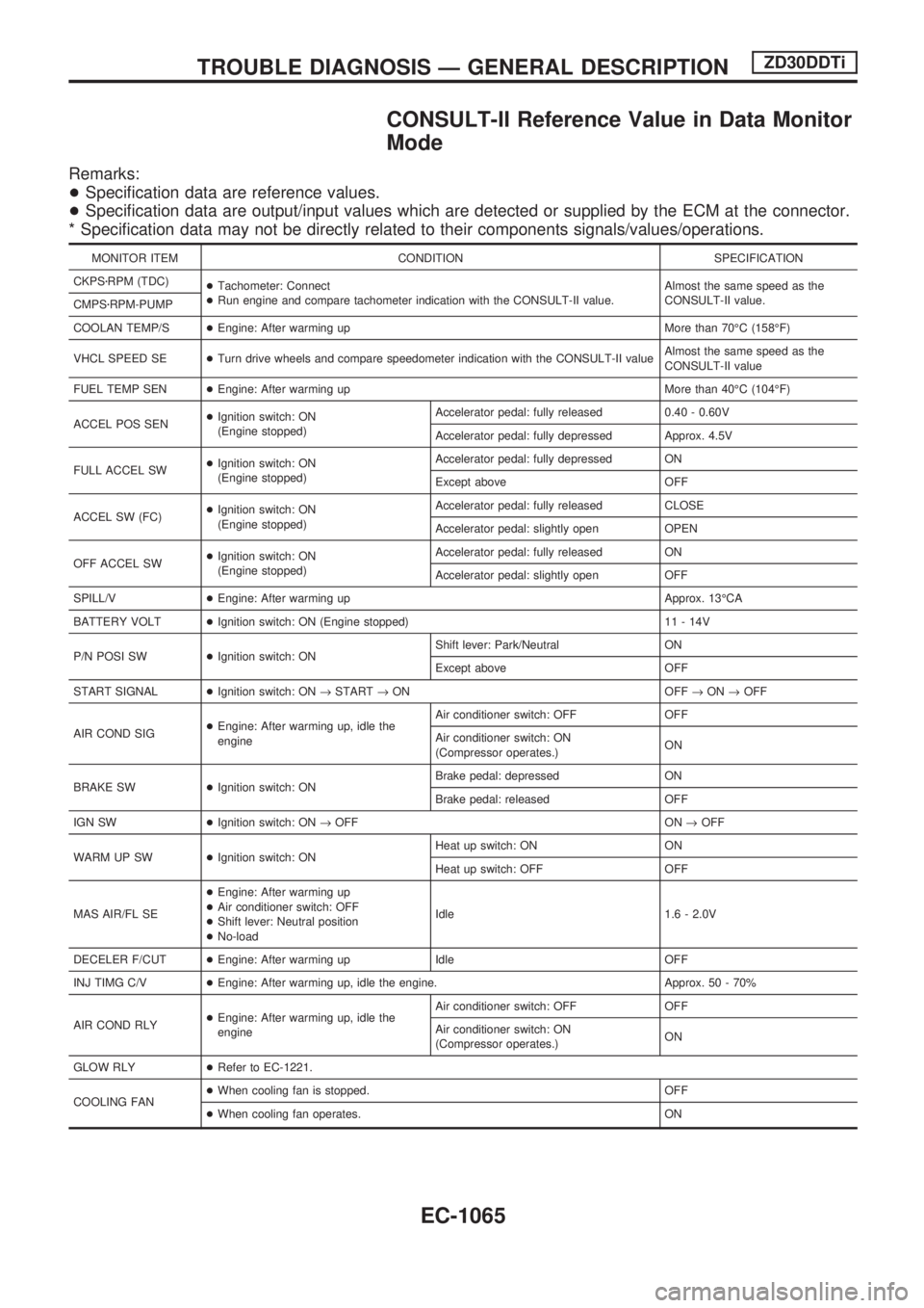
CONSULT-II Reference Value in Data Monitor
Mode
Remarks:
+Specification data are reference values.
+Specification data are output/input values which are detected or supplied by the ECM at the connector.
* Specification data may not be directly related to their components signals/values/operations.
MONITOR ITEM CONDITION SPECIFICATION
CKPSzRPM (TDC)
+Tachometer: Connect
+Run engine and compare tachometer indication with the CONSULT-II value.Almost the same speed as the
CONSULT-II value.
CMPSzRPM-PUMP
COOLAN TEMP/S+Engine: After warming up More than 70ÉC (158ÉF)
VHCL SPEED SE+Turn drive wheels and compare speedometer indication with the CONSULT-II valueAlmost the same speed as the
CONSULT-II value
FUEL TEMP SEN+Engine: After warming up More than 40ÉC (104ÉF)
ACCEL POS SEN+Ignition switch: ON
(Engine stopped)Accelerator pedal: fully released 0.40 - 0.60V
Accelerator pedal: fully depressed Approx. 4.5V
FULL ACCEL SW+Ignition switch: ON
(Engine stopped)Accelerator pedal: fully depressed ON
Except above OFF
ACCEL SW (FC)+Ignition switch: ON
(Engine stopped)Accelerator pedal: fully released CLOSE
Accelerator pedal: slightly open OPEN
OFF ACCEL SW+Ignition switch: ON
(Engine stopped)Accelerator pedal: fully released ON
Accelerator pedal: slightly open OFF
SPILL/V+Engine: After warming up Approx. 13ÉCA
BATTERY VOLT+Ignition switch: ON (Engine stopped) 11 - 14V
P/N POSI SW+Ignition switch: ONShift lever: Park/Neutral ON
Except above OFF
START SIGNAL+Ignition switch: ON®START®ON OFF®ON®OFF
AIR COND SIG+Engine: After warming up, idle the
engineAir conditioner switch: OFF OFF
Air conditioner switch: ON
(Compressor operates.)ON
BRAKE SW+Ignition switch: ONBrake pedal: depressed ON
Brake pedal: released OFF
IGN SW+Ignition switch: ON®OFF ON®OFF
WARM UP SW+Ignition switch: ONHeat up switch: ON ON
Heat up switch: OFF OFF
MAS AIR/FL SE+Engine: After warming up
+Air conditioner switch: OFF
+Shift lever: Neutral position
+No-loadIdle 1.6 - 2.0V
DECELER F/CUT+Engine: After warming up Idle OFF
INJ TIMG C/V+Engine: After warming up, idle the engine. Approx. 50 - 70%
AIR COND RLY+Engine: After warming up, idle the
engineAir conditioner switch: OFF OFF
Air conditioner switch: ON
(Compressor operates.)ON
GLOW RLY+Refer to EC-1221.
COOLING FAN+When cooling fan is stopped. OFF
+When cooling fan operates. ON
TROUBLE DIAGNOSIS Ð GENERAL DESCRIPTIONZD30DDTi
EC-1065