air condition NISSAN PATROL 2000 Electronic Service Manual
[x] Cancel search | Manufacturer: NISSAN, Model Year: 2000, Model line: PATROL, Model: NISSAN PATROL 2000Pages: 1033, PDF Size: 30.71 MB
Page 435 of 1033
Component Description
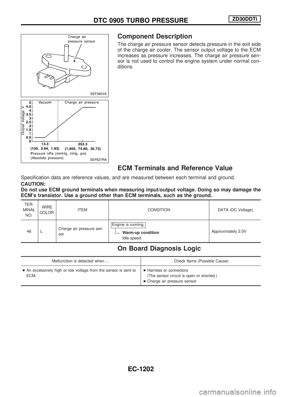
The charge air pressure sensor detects pressure in the exit side
of the charge air cooler. The sensor output voltage to the ECM
increases as pressure increases. The charge air pressure sen-
sor is not used to control the engine system under normal con-
ditions.
ECM Terminals and Reference Value
Specification data are reference values, and are measured between each terminal and ground.
CAUTION:
Do not use ECM ground terminals when measuring input/output voltage. Doing so may damage the
ECM's transistor. Use a ground other than ECM terminals, such as the ground.
TER-
MINAL
NO.WIRE
COLORITEM CONDITION DATA (DC Voltage)
46 LCharge air pressure sen-
sorEngine is running.
Warm-up condition
Idle speedApproximately 2.0V
On Board Diagnosis Logic
Malfunction is detected when ... Check Items (Possible Cause)
+An excessively high or low voltage from the sensor is sent to
ECM.+Harness or connectors
(The sensor circuit is open or shorted.)
+Charge air pressure sensor
SEF340VA
SEF627RA
DTC 0905 TURBO PRESSUREZD30DDTi
EC-1202
Page 440 of 1033
Description
SYSTEM DESCRIPTION
Sensor Input Signal to ECM ECM Function Actuator
Electronic controlled fuel injection pump Fuel injection signal
EGR volume control EGR volume control valve Crankshaft position sensor (TDC) Engine speed
Vehicle speed sensor Vehicle speed
Engine coolant temperature sensor Engine coolant temperature
Ignition switch Start signal
Throttle position sensor Throttle position
Battery Battery voltage
Mass air flow sensor Amount of intake air
Air conditioner switch Air conditioner operation
Electrical load Electrical load signal
PNP switch Park/Neutral position signal
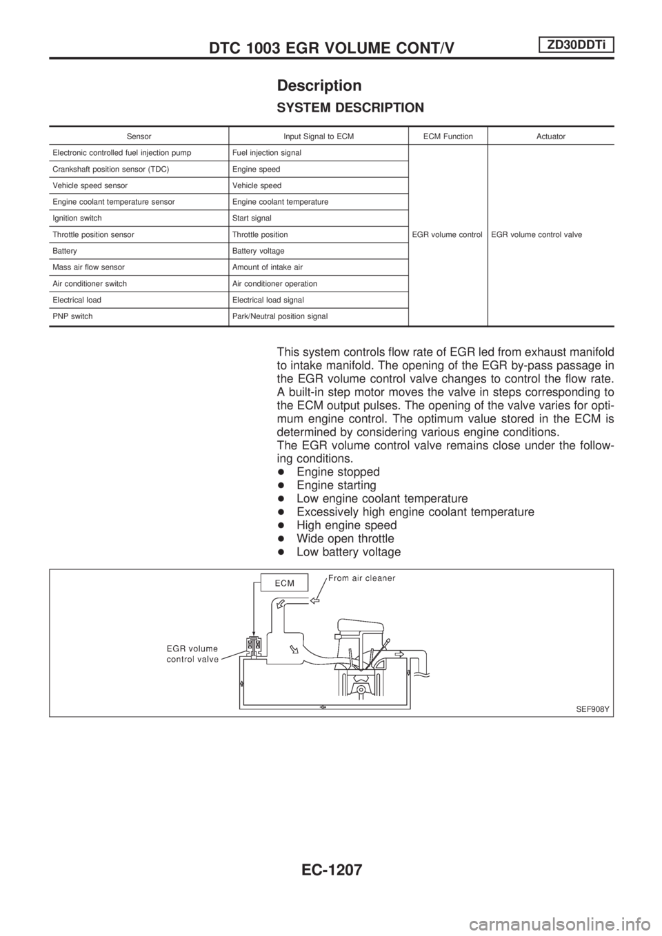
This system controls flow rate of EGR led from exhaust manifold
to intake manifold. The opening of the EGR by-pass passage in
the EGR volume control valve changes to control the flow rate.
A built-in step motor moves the valve in steps corresponding to
the ECM output pulses. The opening of the valve varies for opti-
mum engine control. The optimum value stored in the ECM is
determined by considering various engine conditions.
The EGR volume control valve remains close under the follow-
ing conditions.
+Engine stopped
+Engine starting
+Low engine coolant temperature
+Excessively high engine coolant temperature
+High engine speed
+Wide open throttle
+Low battery voltage
SEF908Y
DTC 1003 EGR VOLUME CONT/VZD30DDTi
EC-1207
Page 441 of 1033
COMPONENT DESCRIPTION
EGR volume control valve
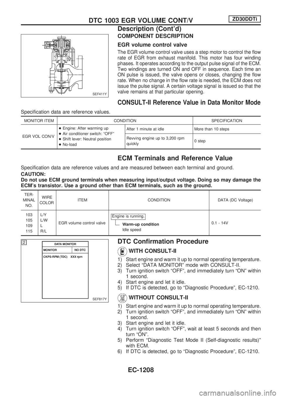
The EGR volume control valve uses a step motor to control the flow
rate of EGR from exhaust manifold. This motor has four winding
phases. It operates according to the output pulse signal of the ECM.
Two windings are turned ON and OFF in sequence. Each time an
ON pulse is issued, the valve opens or closes, changing the flow
rate. When no change in the flow rate is needed, the ECM does not
issue the pulse signal. A certain voltage signal is issued so that the
valve remains at that particular opening.
CONSULT-II Reference Value in Data Monitor Mode
Specification data are reference values.
MONITOR ITEM CONDITION SPECIFICATION
EGR VOL CON/V+Engine: After warming up
+Air conditioner switch: ªOFFº
+Shift lever: Neutral position
+No-loadAfter 1 minute at idle More than 10 steps
Revving engine up to 3,200 rpm
quickly0 step
ECM Terminals and Reference Value
Specification data are reference values and are measured between each terminal and ground.
CAUTION:
Do not use ECM ground terminals when measuring input/output voltage. Doing so may damage the
ECM's transistor. Use a ground other than ECM terminals, such as the ground.
TER-
MINAL
NO.WIRE
COLORITEM CONDITION DATA (DC Voltage)
103
105
109
115L/Y
L/W
L
R/LEGR volume control valveEngine is running.
Warm-up condition
Idle speed0.1 - 14V
DTC Confirmation Procedure
WITH CONSULT-II
1) Start engine and warm it up to normal operating temperature.
2) Select ªDATA MONITORº mode with CONSULT-II.
3) Turn ignition switch ªOFFº, and immediately turn ªONº within
1 second.
4) Start engine and let it idle.
5) If DTC is detected, go to ªDiagnostic Procedureº, EC-1210.
WITHOUT CONSULT-II
1) Start engine and warm it up to normal operating temperature.
2) Turn ignition switch ªOFFº, and immediately turn ªONº within
1 second.
3) Start engine and let it idle.
4) Turn ignition switch ªOFFº, wait at least 5 seconds and then
turn ªONº.
5) Perform ªDiagnostic Test Mode II (Self-diagnostic results)º
with ECM.
6) If DTC is detected, go to ªDiagnostic Procedureº, EC-1210.
SEF411Y
SEF817Y
DTC 1003 EGR VOLUME CONT/VZD30DDTi
Description (Cont'd)
EC-1208
Page 461 of 1033
14 DETECT MALFUNCTIONING PART
Check the following.
+Harness connectors E127, M21
+Harness connectors M51, F6
+Harness for open or short between glow relay and ECM
cRepair open circuit or short to ground or short to power in harness or connectors.
15 CHECK HARNESS CONTINUITY BETWEEN GLOW RELAY AND GLOW PLUG FOR OPEN AND SHORT
1. Disconnect glow plug harness connector.
2. Check harness continuity between glow relay terminal 5 and glow plug harness connector. Refer to Wiring Diagram.
Continuity should exist.
3. Also check harness for short to ground and short to power.
OK or NG
OKcGO TO 16.
NGcRepair open circuit or short to ground or short to power in harness or connectors.
16 DETECT MALFUNCTIONING PART
Check the following.
+Harness connectors E67, E223
+Harness connectors E225, E241
+Harness for open or short between glow relay and glow plug
cRepair open circuit or short to ground or short to power in harness or connectors.
17 CHECK GLOW RELAY
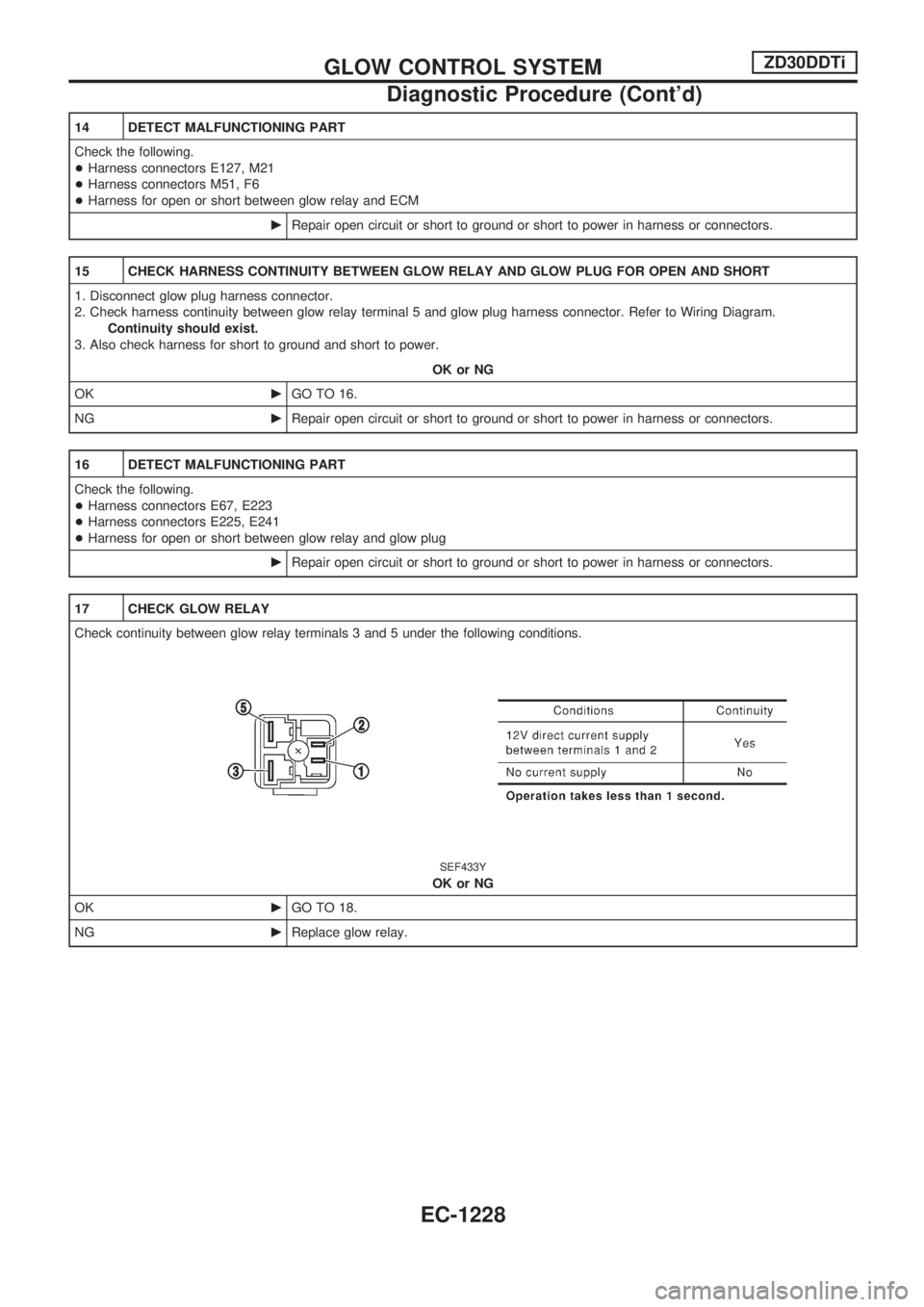
Check continuity between glow relay terminals 3 and 5 under the following conditions.
SEF433Y
OK or NG
OKcGO TO 18.
NGcReplace glow relay.
GLOW CONTROL SYSTEMZD30DDTi
Diagnostic Procedure (Cont'd)
EC-1228
Page 464 of 1033

Diagnostic Procedure
1 CHECK START SIGNAL OVERALL FUNCTION
With CONSULT-II
1. Turn ignition switch ªONº.
2. Check ªSTART SIGNALº in ªDATA MONITORº mode with CONSULT-II under the following conditions.
SEF604X
Without CONSULT-II
Check voltage between ECM terminal 20 and ground under the following conditions.
SEF415Y
OK or NG
OKcINSPECTION END
NGcGO TO 2.
2 CHECK START SIGNAL INPUT SIGNAL CIRCUIT
1. Turn ignition switch ªOFFº.
2. Disconnect ECM harness connector and ignition switch harness connector.
3. Check harness continuity between ECM terminal 20 and ignition switch terminal 6. Refer to Wiring Diagram.
Continuity should exist.
4. Also check harness for short to ground and short to power.
OK or NG
OKcGO TO 4.
NGcGO TO 3.
3 DETECT MALFUNCTIONING PART
Check the following.
+Harness connectors M52, F7
+7.5A fuse
+Fuse block (J/B) connectors M3, E112
+Harness for open or short between ECM and ignition switch
cRepair open circuit or short to ground or short to power in harness or connectors.
START SIGNALZD30DDTi
EC-1231
Page 472 of 1033
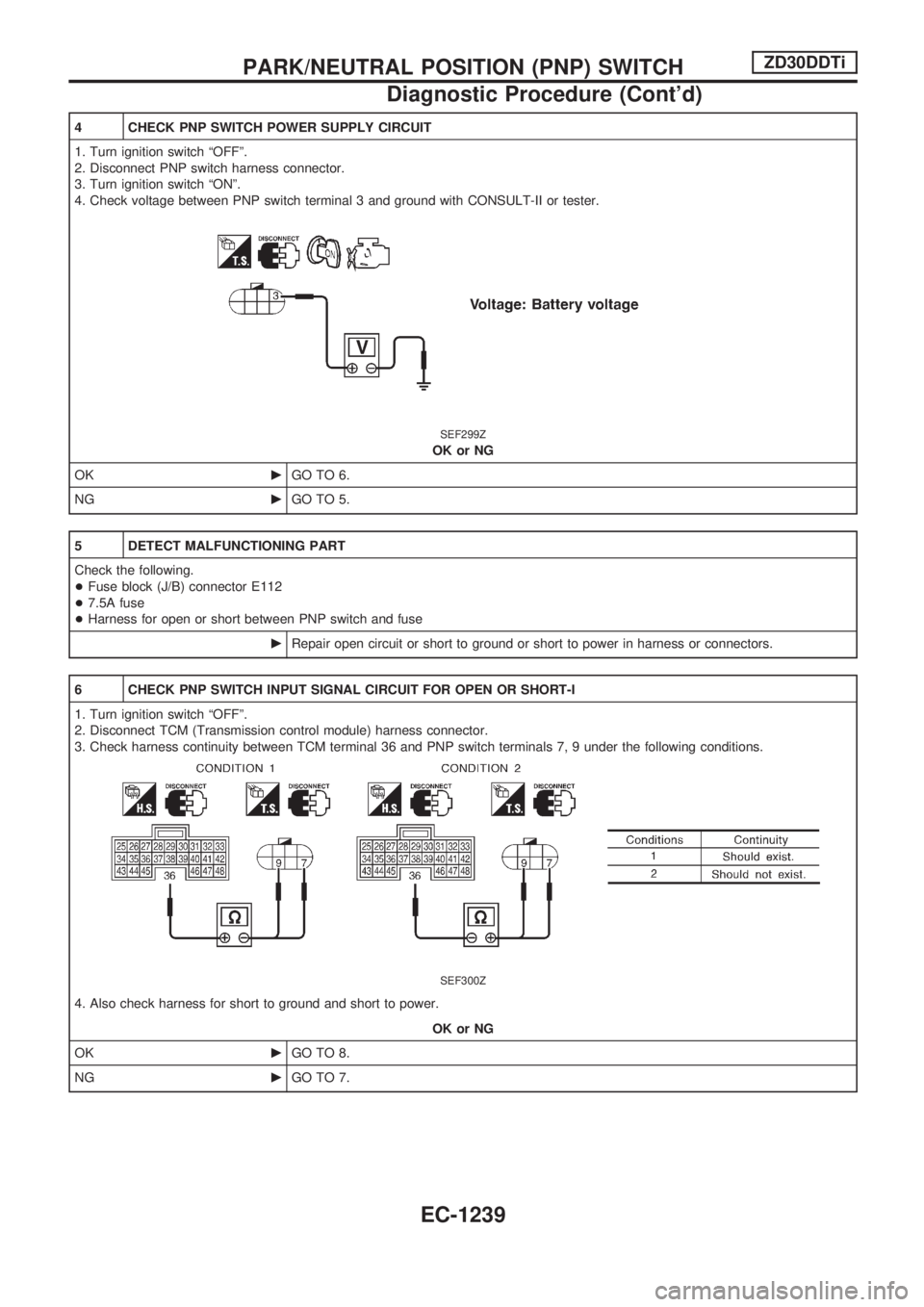
4 CHECK PNP SWITCH POWER SUPPLY CIRCUIT
1. Turn ignition switch ªOFFº.
2. Disconnect PNP switch harness connector.
3. Turn ignition switch ªONº.
4. Check voltage between PNP switch terminal 3 and ground with CONSULT-II or tester.
SEF299Z
OK or NG
OKcGO TO 6.
NGcGO TO 5.
5 DETECT MALFUNCTIONING PART
Check the following.
+Fuse block (J/B) connector E112
+7.5A fuse
+Harness for open or short between PNP switch and fuse
cRepair open circuit or short to ground or short to power in harness or connectors.
6 CHECK PNP SWITCH INPUT SIGNAL CIRCUIT FOR OPEN OR SHORT-I
1. Turn ignition switch ªOFFº.
2. Disconnect TCM (Transmission control module) harness connector.
3. Check harness continuity between TCM terminal 36 and PNP switch terminals 7, 9 under the following conditions.
SEF300Z
4. Also check harness for short to ground and short to power.
OK or NG
OKcGO TO 8.
NGcGO TO 7.
PARK/NEUTRAL POSITION (PNP) SWITCHZD30DDTi
Diagnostic Procedure (Cont'd)
EC-1239
Page 479 of 1033
Description
SYSTEM DESCRIPTION
Sensor Input Signal to ECMECM
FunctionActuator
Ignition switch Start signal
Swirl
control
valve
controlSwirl control valve control solenoid valve
¯Vacuum signal
Swirl control valve actuator
¯Swirl control valve Crankshaft position sensor (TDC) Engine speed
PNP switch Park/Neutral position signal
Engine coolant temperature sensor Engine coolant temperature
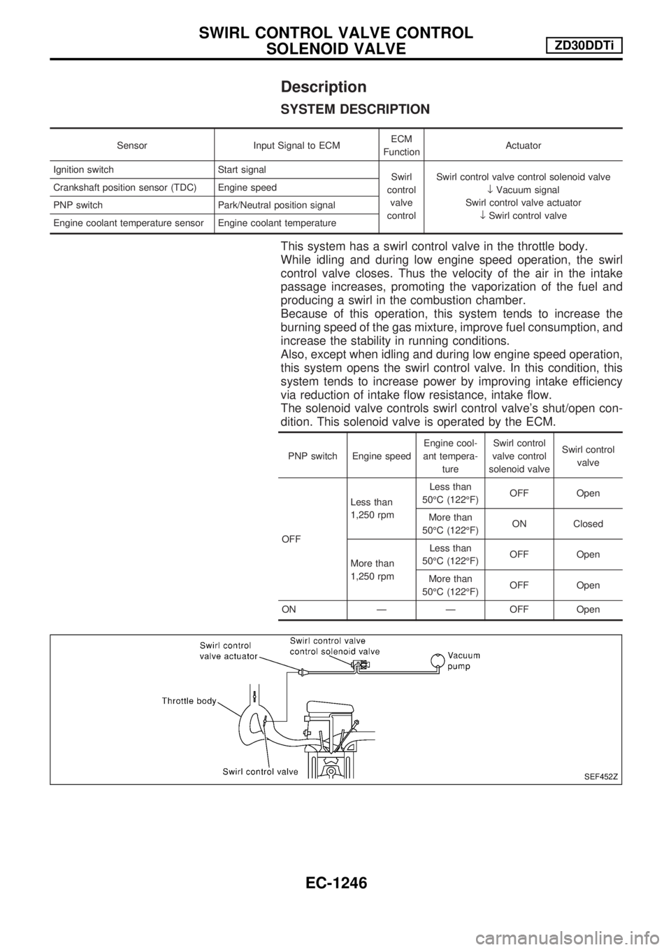
This system has a swirl control valve in the throttle body.
While idling and during low engine speed operation, the swirl
control valve closes. Thus the velocity of the air in the intake
passage increases, promoting the vaporization of the fuel and
producing a swirl in the combustion chamber.
Because of this operation, this system tends to increase the
burning speed of the gas mixture, improve fuel consumption, and
increase the stability in running conditions.
Also, except when idling and during low engine speed operation,
this system opens the swirl control valve. In this condition, this
system tends to increase power by improving intake efficiency
via reduction of intake flow resistance, intake flow.
The solenoid valve controls swirl control valve's shut/open con-
dition. This solenoid valve is operated by the ECM.
PNP switch Engine speedEngine cool-
ant tempera-
tureSwirl control
valve control
solenoid valveSwirl control
valve
OFFLess than
1,250 rpmLess than
50ÉC (122ÉF)OFF Open
More than
50ÉC (122ÉF)ON Closed
More than
1,250 rpmLess than
50ÉC (122ÉF)OFF Open
More than
50ÉC (122ÉF)OFF Open
ON Ð Ð OFF Open
SEF452Z
SWIRL CONTROL VALVE CONTROL
SOLENOID VALVEZD30DDTi
EC-1246
Page 480 of 1033
COMPONENT DESCRIPTION
Swirl control valve control solenoid valve
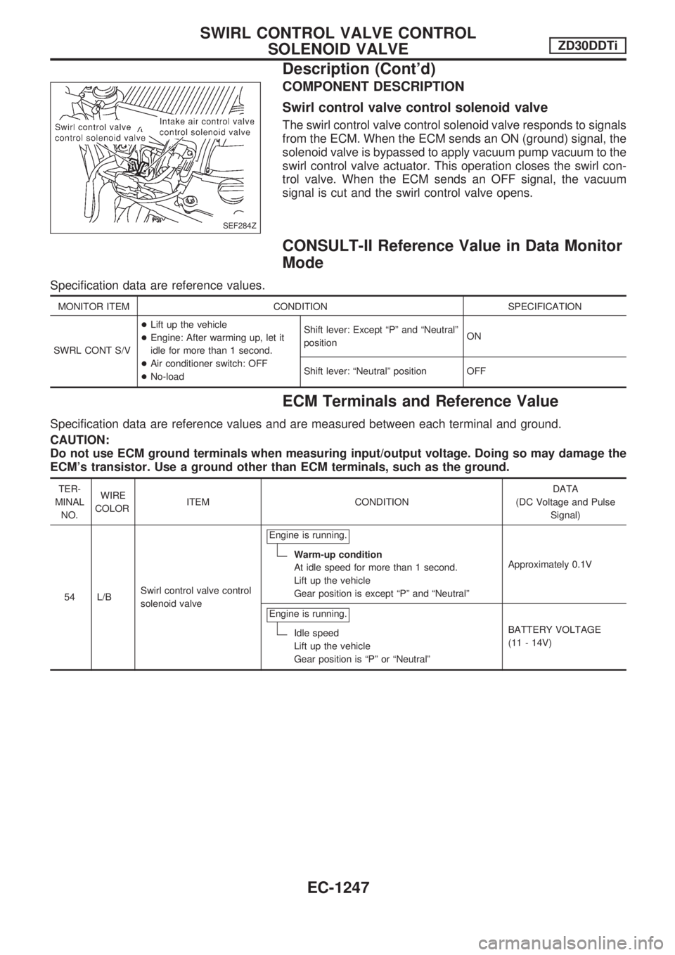
The swirl control valve control solenoid valve responds to signals
from the ECM. When the ECM sends an ON (ground) signal, the
solenoid valve is bypassed to apply vacuum pump vacuum to the
swirl control valve actuator. This operation closes the swirl con-
trol valve. When the ECM sends an OFF signal, the vacuum
signal is cut and the swirl control valve opens.
CONSULT-II Reference Value in Data Monitor
Mode
Specification data are reference values.
MONITOR ITEM CONDITION SPECIFICATION
SWRL CONT S/V+Lift up the vehicle
+Engine: After warming up, let it
idle for more than 1 second.
+Air conditioner switch: OFF
+No-loadShift lever: Except ªPº and ªNeutralº
positionON
Shift lever: ªNeutralº position OFF
ECM Terminals and Reference Value
Specification data are reference values and are measured between each terminal and ground.
CAUTION:
Do not use ECM ground terminals when measuring input/output voltage. Doing so may damage the
ECM's transistor. Use a ground other than ECM terminals, such as the ground.
TER-
MINAL
NO.WIRE
COLORITEM CONDITIONDATA
(DC Voltage and Pulse
Signal)
54 L/BSwirl control valve control
solenoid valveEngine is running.
Warm-up condition
At idle speed for more than 1 second.
Lift up the vehicle
Gear position is except ªPº and ªNeutralºApproximately 0.1V
Engine is running.
Idle speed
Lift up the vehicle
Gear position is ªPº or ªNeutralºBATTERY VOLTAGE
(11 - 14V)
SEF284Z
SWIRL CONTROL VALVE CONTROL
SOLENOID VALVEZD30DDTi
Description (Cont'd)
EC-1247
Page 486 of 1033
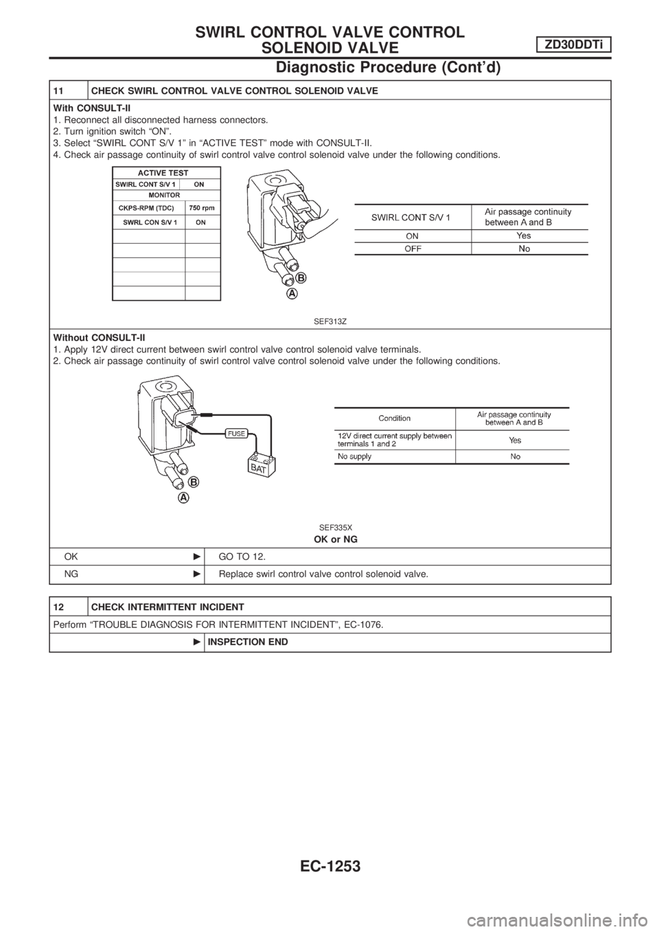
11 CHECK SWIRL CONTROL VALVE CONTROL SOLENOID VALVE
With CONSULT-II
1. Reconnect all disconnected harness connectors.
2. Turn ignition switch ªONº.
3. Select ªSWIRL CONT S/V 1º in ªACTIVE TESTº mode with CONSULT-II.
4. Check air passage continuity of swirl control valve control solenoid valve under the following conditions.
SEF313Z
Without CONSULT-II
1. Apply 12V direct current between swirl control valve control solenoid valve terminals.
2. Check air passage continuity of swirl control valve control solenoid valve under the following conditions.
SEF335X
OK or NG
OKcGO TO 12.
NGcReplace swirl control valve control solenoid valve.
12 CHECK INTERMITTENT INCIDENT
Perform ªTROUBLE DIAGNOSIS FOR INTERMITTENT INCIDENTº, EC-1076.
cINSPECTION END
SWIRL CONTROL VALVE CONTROL
SOLENOID VALVEZD30DDTi
Diagnostic Procedure (Cont'd)
EC-1253
Page 487 of 1033
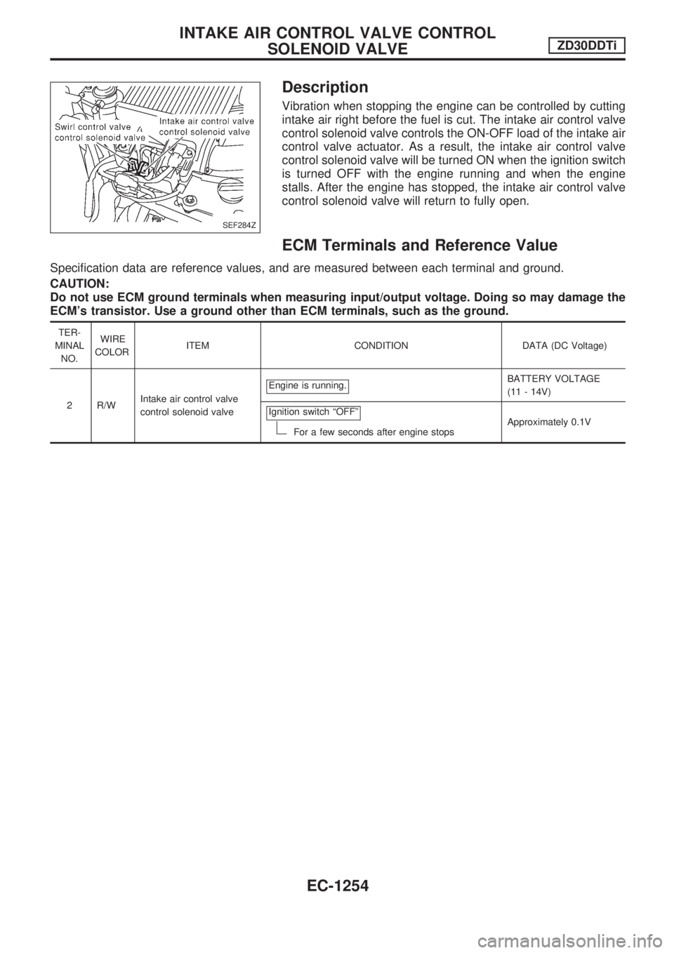
Description
Vibration when stopping the engine can be controlled by cutting
intake air right before the fuel is cut. The intake air control valve
control solenoid valve controls the ON-OFF load of the intake air
control valve actuator. As a result, the intake air control valve
control solenoid valve will be turned ON when the ignition switch
is turned OFF with the engine running and when the engine
stalls. After the engine has stopped, the intake air control valve
control solenoid valve will return to fully open.
ECM Terminals and Reference Value
Specification data are reference values, and are measured between each terminal and ground.
CAUTION:
Do not use ECM ground terminals when measuring input/output voltage. Doing so may damage the
ECM's transistor. Use a ground other than ECM terminals, such as the ground.
TER-
MINAL
NO.WIRE
COLORITEM CONDITION DATA (DC Voltage)
2 R/WIntake air control valve
control solenoid valveEngine is running.
BATTERY VOLTAGE
(11 - 14V)
Ignition switch ªOFFº
For a few seconds after engine stopsApproximately 0.1V
SEF284Z
INTAKE AIR CONTROL VALVE CONTROL
SOLENOID VALVEZD30DDTi
EC-1254