air condition NISSAN PATROL 2000 Electronic Workshop Manual
[x] Cancel search | Manufacturer: NISSAN, Model Year: 2000, Model line: PATROL, Model: NISSAN PATROL 2000Pages: 1033, PDF Size: 30.71 MB
Page 489 of 1033
Diagnostic Procedure
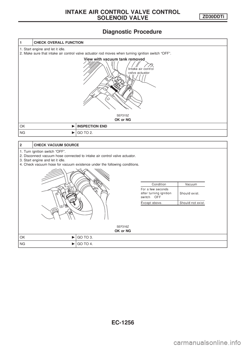
1 CHECK OVERALL FUNCTION
1. Start engine and let it idle.
2. Make sure that intake air control valve actuator rod moves when turning ignition switch ªOFFº.
SEF315Z
OK or NG
OKcINSPECTION END
NGcGO TO 2.
2 CHECK VACUUM SOURCE
1. Turn ignition switch ªOFFº.
2. Disconnect vacuum hose connected to intake air control valve actuator.
3. Start engine and let it idle.
4. Check vacuum hose for vacuum existence under the following conditions.
SEF316Z
OK or NG
OKcGO TO 3.
NGcGO TO 4.
INTAKE AIR CONTROL VALVE CONTROL
SOLENOID VALVEZD30DDTi
EC-1256
Page 493 of 1033
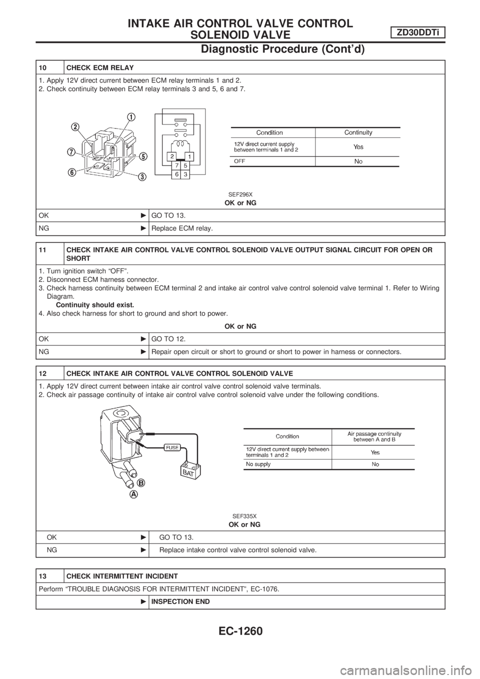
10 CHECK ECM RELAY
1. Apply 12V direct current between ECM relay terminals 1 and 2.
2. Check continuity between ECM relay terminals 3 and 5, 6 and 7.
SEF296X
OK or NG
OKcGO TO 13.
NGcReplace ECM relay.
11 CHECK INTAKE AIR CONTROL VALVE CONTROL SOLENOID VALVE OUTPUT SIGNAL CIRCUIT FOR OPEN OR
SHORT
1. Turn ignition switch ªOFFº.
2. Disconnect ECM harness connector.
3. Check harness continuity between ECM terminal 2 and intake air control valve control solenoid valve terminal 1. Refer to Wiring
Diagram.
Continuity should exist.
4. Also check harness for short to ground and short to power.
OK or NG
OKcGO TO 12.
NGcRepair open circuit or short to ground or short to power in harness or connectors.
12 CHECK INTAKE AIR CONTROL VALVE CONTROL SOLENOID VALVE
1. Apply 12V direct current between intake air control valve control solenoid valve terminals.
2. Check air passage continuity of intake air control valve control solenoid valve under the following conditions.
SEF335X
OK or NG
OKcGO TO 13.
NGcReplace intake control valve control solenoid valve.
13 CHECK INTERMITTENT INCIDENT
Perform ªTROUBLE DIAGNOSIS FOR INTERMITTENT INCIDENTº, EC-1076.
cINSPECTION END
INTAKE AIR CONTROL VALVE CONTROL
SOLENOID VALVEZD30DDTi
Diagnostic Procedure (Cont'd)
EC-1260
Page 494 of 1033
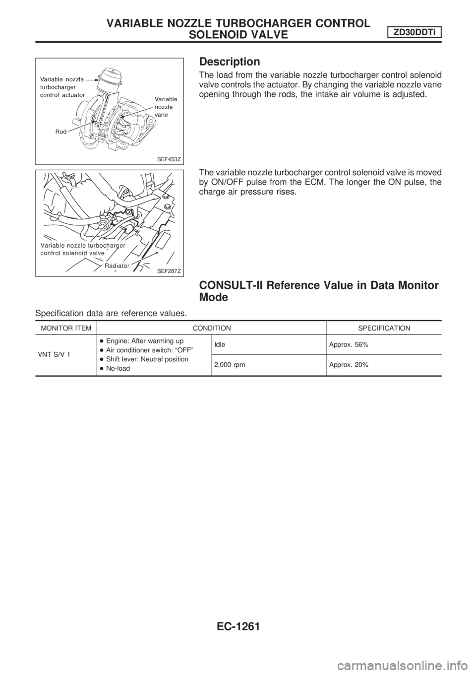
Description
The load from the variable nozzle turbocharger control solenoid
valve controls the actuator. By changing the variable nozzle vane
opening through the rods, the intake air volume is adjusted.
The variable nozzle turbocharger control solenoid valve is moved
by ON/OFF pulse from the ECM. The longer the ON pulse, the
charge air pressure rises.
CONSULT-II Reference Value in Data Monitor
Mode
Specification data are reference values.
MONITOR ITEM CONDITION SPECIFICATION
VNT S/V 1+Engine: After warming up
+Air conditioner switch: ªOFFº
+Shift lever: Neutral position
+No-loadIdle Approx. 56%
2,000 rpm Approx. 20%
SEF453Z
SEF287Z
VARIABLE NOZZLE TURBOCHARGER CONTROL
SOLENOID VALVEZD30DDTi
EC-1261
Page 501 of 1033
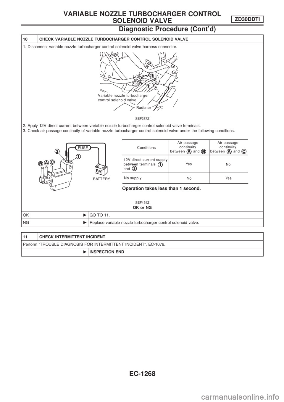
10 CHECK VARIABLE NOZZLE TURBOCHARGER CONTROL SOLENOID VALVE
1. Disconnect variable nozzle turbocharger control solenoid valve harness connector.
SEF287Z
2. Apply 12V direct current between variable nozzle turbocharger control solenoid valve terminals.
3. Check air passage continuity of variable nozzle turbocharger control solenoid valve under the following conditions.
SEF454Z
OK or NG
OKcGO TO 11.
NGcReplace variable nozzle turbocharger control solenoid valve.
11 CHECK INTERMITTENT INCIDENT
Perform ªTROUBLE DIAGNOSIS FOR INTERMITTENT INCIDENTº, EC-1076.
cINSPECTION END
VARIABLE NOZZLE TURBOCHARGER CONTROL
SOLENOID VALVEZD30DDTi
Diagnostic Procedure (Cont'd)
EC-1268
Page 507 of 1033
7 DETECT MALFUNCTIONING PART
Check the following.
+Harness connectors M21, E127
+Fuse block (J/B) connector M2
+10A fuse
+Harness for open or short between exhaust gas control valve control solenoid valve and fuse
cRepair open circuit or short to ground or short to power in harness or connectors.
8 CHECK EXHAUST GAS CONTROL VALVE CONTROL SOLENOID VALVE OUTPUT SIGNAL CIRCUIT FOR OPEN
OR SHORT
1. Turn ignition switch ªOFFº.
2. Disconnect ECM harness connector.
3. Check harness continuity between ECM terminal 11 and exhaust gas control valve control solenoid valve terminal 1. Refer to
Wiring Diagram.
Continuity should exist.
4. Also check harness for short to ground and short to power.
OK or NG
OKcGO TO 10.
NGcGO TO 9.
9 DETECT MALFUNCTIONING PART
Check the following.
+Harness connectors M21, E127
+Harness connectors M50, F5
+Harness for open or short between exhaust gas control valve control solenoid valve and ECM
cRepair open circuit or short to ground or short to power in harness or connectors.
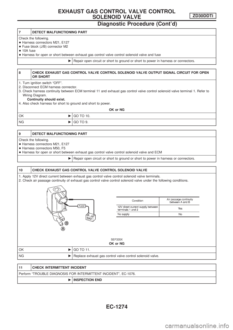
10 CHECK EXHAUST GAS CONTROL VALVE CONTROL SOLENOID VALVE
1. Apply 12V direct current between exhaust gas control valve control solenoid valve terminals.
2. Check air passage continuity of exhaust gas control valve control solenoid valve under the following conditions.
SEF335X
OK or NG
OKcGO TO 11.
NGcReplace exhaust gas control valve control solenoid valve.
11 CHECK INTERMITTENT INCIDENT
Perform ªTROUBLE DIAGNOSIS FOR INTERMITTENT INCIDENTº, EC-1076.
cINSPECTION END
EXHAUST GAS CONTROL VALVE CONTROL
SOLENOID VALVEZD30DDTi
Diagnostic Procedure (Cont'd)
EC-1274
Page 508 of 1033
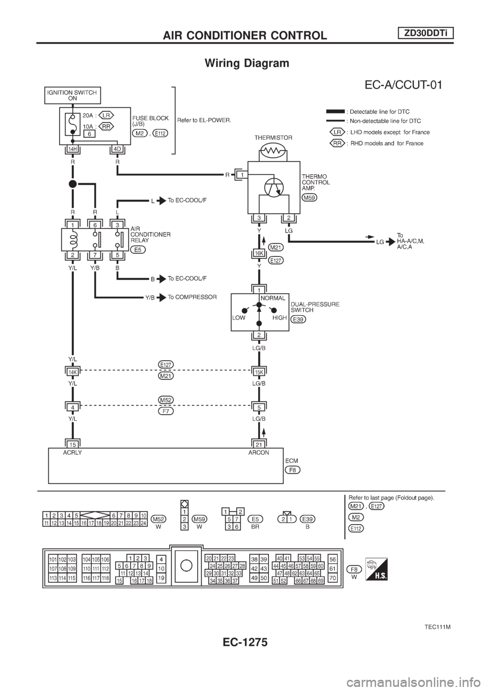
Wiring Diagram
TEC111M
AIR CONDITIONER CONTROLZD30DDTi
EC-1275
Page 606 of 1033
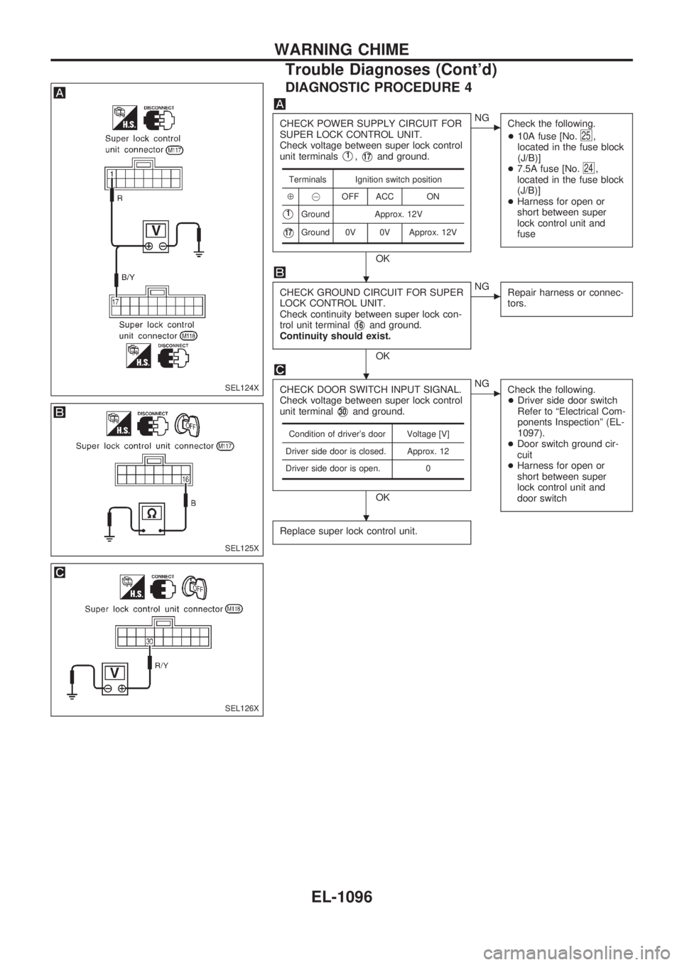
DIAGNOSTIC PROCEDURE 4
CHECK POWER SUPPLY CIRCUIT FOR
SUPER LOCK CONTROL UNIT.
Check voltage between super lock control
unit terminals
V1,V17and ground.
OK
cNG
Check the following.
+10A fuse [No.
25,
located in the fuse block
(J/B)]
+7.5A fuse [No.
24,
located in the fuse block
(J/B)]
+Harness for open or
short between super
lock control unit and
fuse
CHECK GROUND CIRCUIT FOR SUPER
LOCK CONTROL UNIT.
Check continuity between super lock con-
trol unit terminal
V16and ground.
Continuity should exist.
OK
cNG
Repair harness or connec-
tors.
CHECK DOOR SWITCH INPUT SIGNAL.
Check voltage between super lock control
unit terminal
V30and ground.
OK
cNG
Check the following.
+Driver side door switch
Refer to ªElectrical Com-
ponents Inspectionº (EL-
1097).
+Door switch ground cir-
cuit
+Harness for open or
short between super
lock control unit and
door switch
Replace super lock control unit.
Terminals Ignition switch position
Å@OFF ACC ON
V1Ground Approx. 12V
V17Ground 0V 0V Approx. 12V
Condition of driver's door Voltage [V]
Driver side door is closed. Approx. 12
Driver side door is open. 0
SEL124X
SEL125X
SEL126X
.
.
.
WARNING CHIME
Trouble Diagnoses (Cont'd)
EL-1096
Page 616 of 1033
Trouble Diagnoses
SYMPTOM: Rear window defogger does not activate, or
does not go off after activating.
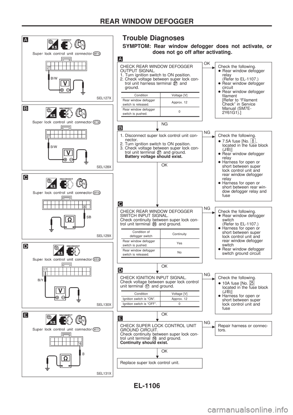
CHECK REAR WINDOW DEFOGGER
OUTPUT SIGNAL.
1. Turn ignition switch to ON position.
2. Check voltage between super lock con-
trol unit harness terminal
V27and
ground.
NG
cOK
Check the following.
+Rear window defogger
relay
(Refer to EL-1107.)
+Rear window defogger
circuit
+Rear window defogger
filament
[Refer to ªFilament
Checkº in Service
Manual (SM7E-
2Y61G1).]
1. Disconnect super lock control unit con-
nector.
2. Turn ignition switch to ON position.
3. Check voltage between super lock con-
trol unit terminal
V27and ground.
Battery voltage should exist.
OK
cNG
Check the following.
+7.5A fuse [No.
8,
located in the fuse block
(J/B)]
+Rear window defogger
relay
+Harness for open or
short between super
lock control unit and
rear window defogger
relay
+Harness for open or
short between rear win-
dow defogger relay and
fuse
CHECK REAR WINDOW DEFOGGER
SWITCH INPUT SIGNAL.
Check continuity between super lock con-
trol unit terminal
V35and ground.
OK
cNG
Check the following.
+Rear window defogger
switch
(Refer to EL-1107.)
+Harness for open or
short between super
lock control unit and
rear window defogger
switch
+Rear window defogger
switch ground circuit
CHECK IGNITION INPUT SIGNAL.
Check voltage between super lock control
unit terminal
V17and ground.
OK
cNG
Check the following.
+10A fuse [No.
25located in the fuse block
(J/B)]
+Harness for open or
short between super
lock control unit and
fuse
CHECK SUPER LOCK CONTROL UNIT
GROUND CIRCUIT.
Check continuity between super lock con-
trol unit terminal
V16and ground.
Continuity should exist.
OK
cNG
Repair harness or connec-
tors.
Replace super lock control unit.
Condition Voltage [V]
Rear window defogger
switch is released.Approx. 12
Rear window defogger
switch is pushed.0
Condition of
defogger switchContinuity
Rear window defogger
switch is pushed.Yes
Rear window defogger
switch is released.No
Condition Voltage [V]
Ignition switch is ªONº. Approx. 12
Ignition switch is ªOFFº. 0
SEL127X
SEL128X
SEL129X
SEL130X
SEL131X
.
.
.
.
.
REAR WINDOW DEFOGGER
EL-1106
Page 633 of 1033
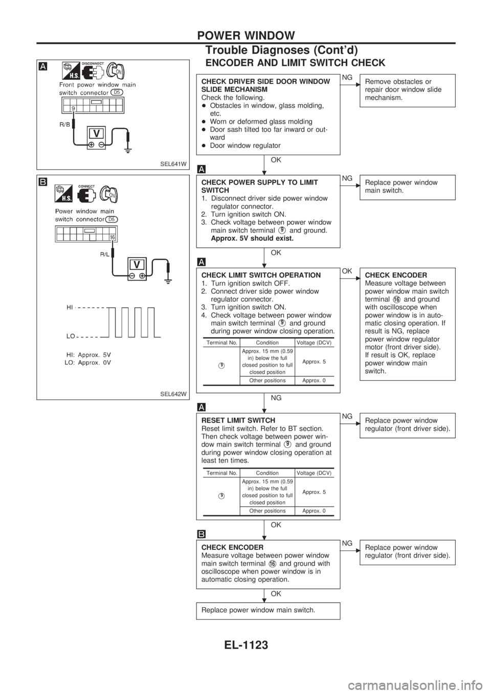
ENCODER AND LIMIT SWITCH CHECK
CHECK DRIVER SIDE DOOR WINDOW
SLIDE MECHANISM
Check the following.
+Obstacles in window, glass molding,
etc.
+Worn or deformed glass molding
+Door sash tilted too far inward or out-
ward
+Door window regulator
OK
cNG
Remove obstacles or
repair door window slide
mechanism.
CHECK POWER SUPPLY TO LIMIT
SWITCH
1. Disconnect driver side power window
regulator connector.
2. Turn ignition switch ON.
3. Check voltage between power window
main switch terminal
V9and ground.
Approx. 5V should exist.
OK
cNG
Replace power window
main switch.
CHECK LIMIT SWITCH OPERATION
1. Turn ignition switch OFF.
2. Connect driver side power window
regulator connector.
3. Turn ignition switch ON.
4. Check voltage between power window
main switch terminal
V9and ground
during power window closing operation.
NG
cOK
CHECK ENCODER
Measure voltage between
power window main switch
terminal
V16and ground
with oscilloscope when
power window is in auto-
matic closing operation. If
result is NG, replace
power window regulator
motor (front driver side).
If result is OK, replace
power window main
switch.
RESET LIMIT SWITCH
Reset limit switch. Refer to BT section.
Then check voltage between power win-
dow main switch terminal
V9and ground
during power window closing operation at
least ten times.
OK
cNG
Replace power window
regulator (front driver side).
CHECK ENCODER
Measure voltage between power window
main switch terminal
V16and ground with
oscilloscope when power window is in
automatic closing operation.
OK
cNG
Replace power window
regulator (front driver side).
Replace power window main switch.
Terminal No. Condition Voltage (DCV)
V9
Approx. 15 mm (0.59
in) below the full
closed position to full
closed positionApprox. 5
Other positions Approx. 0
Terminal No. Condition Voltage (DCV)
V9
Approx. 15 mm (0.59
in) below the full
closed position to full
closed positionApprox. 5
Other positions Approx. 0
SEL641W
SEL642W
.
.
.
.
.
POWER WINDOW
Trouble Diagnoses (Cont'd)
EL-1123
Page 657 of 1033
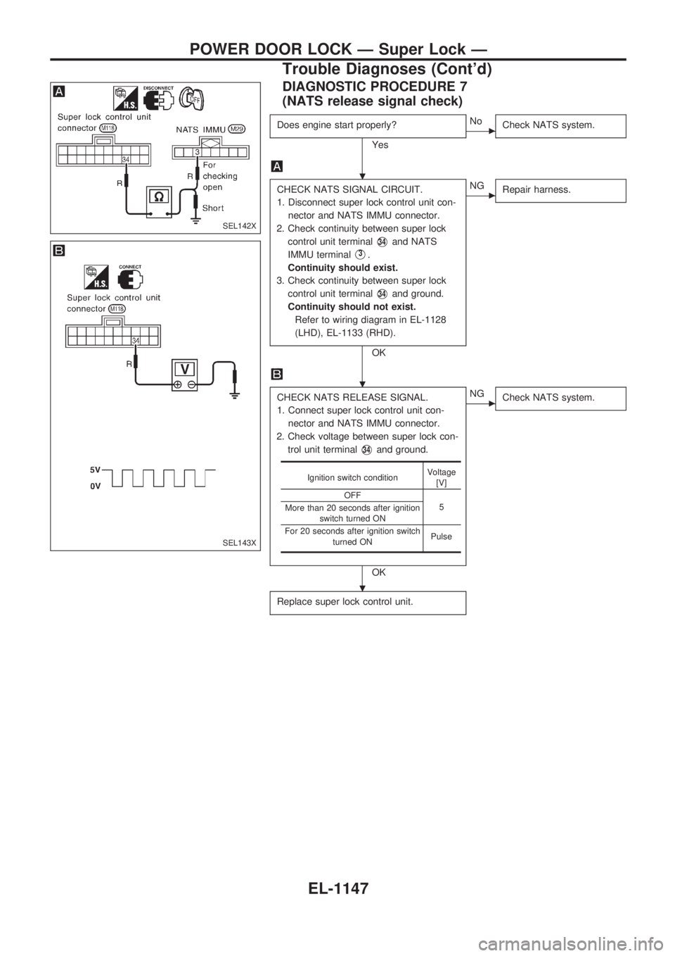
DIAGNOSTIC PROCEDURE 7
(NATS release signal check)
Does engine start properly?
Yes
cNo
Check NATS system.
CHECK NATS SIGNAL CIRCUIT.
1. Disconnect super lock control unit con-
nector and NATS IMMU connector.
2. Check continuity between super lock
control unit terminal
V34and NATS
IMMU terminal
V3.
Continuity should exist.
3. Check continuity between super lock
control unit terminal
V34and ground.
Continuity should not exist.
Refer to wiring diagram in EL-1128
(LHD), EL-1133 (RHD).
OK
cNG
Repair harness.
CHECK NATS RELEASE SIGNAL.
1. Connect super lock control unit con-
nector and NATS IMMU connector.
2. Check voltage between super lock con-
trol unit terminal
V34and ground.
OK
cNG
Check NATS system.
Replace super lock control unit.
Ignition switch conditionVoltage
[V]
OFF
5
More than 20 seconds after ignition
switch turned ON
For 20 seconds after ignition switch
turned ONPulse
SEL142X
SEL143X
.
.
.
POWER DOOR LOCK Ð Super Lock Ð
Trouble Diagnoses (Cont'd)
EL-1147