NISSAN PATROL 2001 Electronic Owner's Guide
Manufacturer: NISSAN, Model Year: 2001, Model line: PATROL, Model: NISSAN PATROL 2001Pages: 273, PDF Size: 9.05 MB
Page 31 of 273
CLUTCH
SECTION
CL
MODIFICATION NOTICE:
+Service Data and Specifications (SDS) have been changed.
CONTENTS
CLUTCH SYSTEM............................................... 2002
HYDRAULIC CLUTCH CONTROL..................... 2003
Clutch Operating Cylinder................................ 2003
Clutch Master Cylinder .................................... 2004
CLUTCH DISC AND CLUTCH COVER.............. 2005Clutch Cover .................................................... 2005
SERVICE DATA AND SPECIFICATIONS
(SDS).................................................................... 2006
General Specifications ..................................... 2006
Inspection and Adjustment .............................. 2006
CL
Page 32 of 273

SCL906
CLUTCH SYSTEM
CL-2002
Page 33 of 273

Clutch Operating Cylinder
SCL907
HYDRAULIC CLUTCH CONTROL
CL-2003
Page 34 of 273

Clutch Master Cylinder
SCL908
HYDRAULIC CLUTCH CONTROL
CL-2004
Page 35 of 273
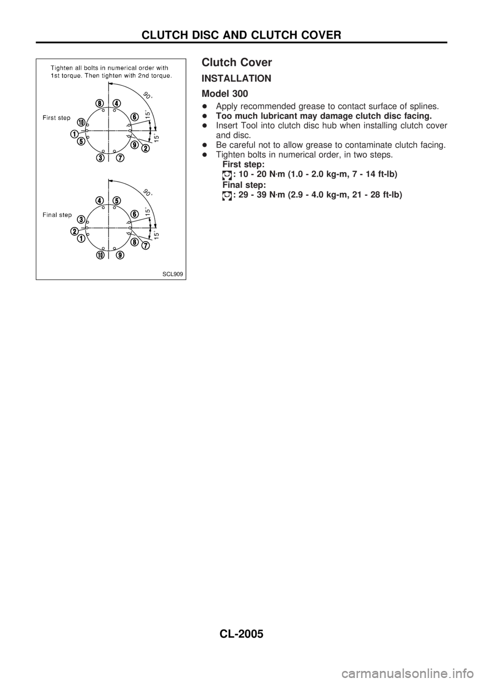
Clutch Cover
INSTALLATION
Model 300
+Apply recommended grease to contact surface of splines.
+Too much lubricant may damage clutch disc facing.
+Insert Tool into clutch disc hub when installing clutch cover
and disc.
+Be careful not to allow grease to contaminate clutch facing.
+Tighten bolts in numerical order, in two steps.
First step:
:10-20Nzm (1.0 - 2.0 kg-m,7-14ft-lb)
Final step:
:29-39Nzm (2.9 - 4.0 kg-m, 21 - 28 ft-lb)
SCL909
CLUTCH DISC AND CLUTCH COVER
CL-2005
Page 36 of 273
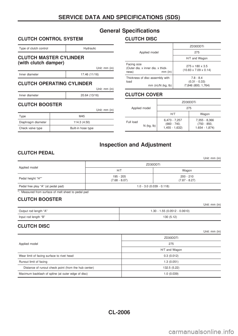
General Specifications
CLUTCH CONTROL SYSTEM
Type of clutch control Hydraulic
CLUTCH MASTER CYLINDER
(with clutch damper)
Unit: mm (in)
Inner diameter 17.46 (11/16)
CLUTCH OPERATING CYLINDER
Unit: mm (in)
Inner diameter 20.64 (13/16)
CLUTCH BOOSTER
Unit: mm (in)
Type M45
Diaphragm diameter 114.3 (4.50)
Check valve type Built-in hose type
CLUTCH DISC
Applied modelZD30DDTi
275
H/T and Wagon
Facing size
(Outer dia. x inner dia. x thick-
ness) mm (in)275 x 180 x 3.5
(10.83 x 7.09 x 0.14)
Thickness of disc assembly with
load
mm (in)/N (kg, lb)7.8 - 8.4
(0.31 - 0.33)
/7,846 (800, 1,764)
CLUTCH COVER
Applied modelZD30DDTi
275
H/T Wagon
Full load
N (kg, lb)6,473 - 7,257
(660 - 740,
1,455 - 1,632)7,355 - 8,366
(750 - 850,
1.654 - 1,874)
Inspection and Adjustment
CLUTCH PEDAL
Unit: mm (in)
Applied modelZD30DDTi
H/T Wagon
Pedal height ªH*º195 - 205
(7.68 - 8.07)200 - 210
(7.87 - 8.27)
Pedal free play ªAº (at pedal pad) 1.0 - 3.0 (0.039 - 0.118)
*: Measured from surface of melt sheet to pedal pad
CLUTCH BOOSTER
Unit: mm (in)
Output rod length ªAº1.30 - 1.55 (0.0512 - 0.0610)
Input rod length ªBº130 (5.12)
CLUTCH DISC
Unit: mm (in)
Applied modelZD30DDTi
275
H/T and Wagon
Wear limit of facing surface to rivet head 0.3 (0.012)
Runout limit of facing1.3 (0.051)
Distance of runout check point (from the hub center) 132.5 (5.22)
Maximum backlash of spline (at outer edge of disc) 1.0 (0.039)
SERVICE DATA AND SPECIFICATIONS (SDS)
CL-2006
Page 37 of 273
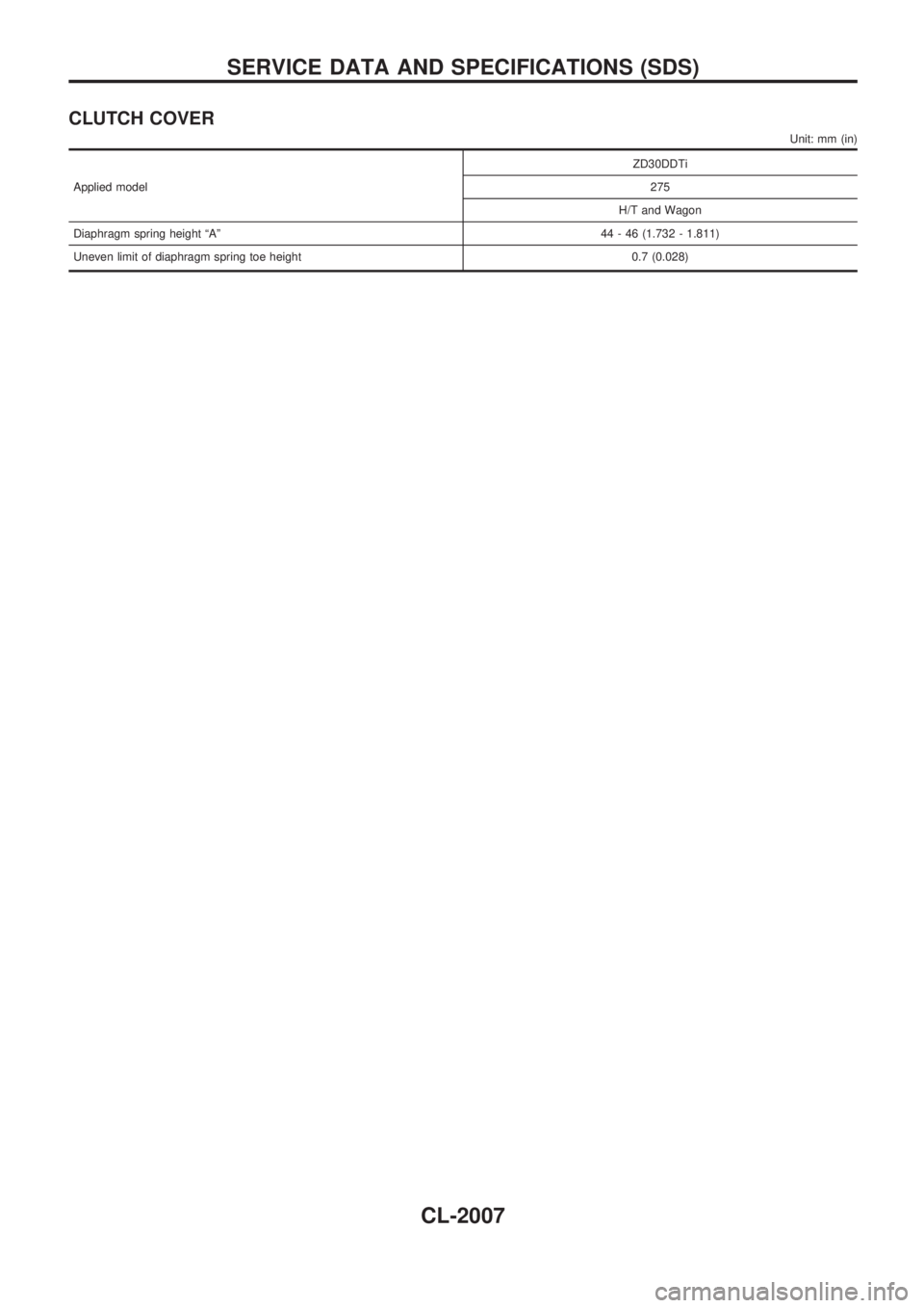
CLUTCH COVER
Unit: mm (in)
Applied modelZD30DDTi
275
H/T and Wagon
Diaphragm spring height ªAº44 - 46 (1.732 - 1.811)
Uneven limit of diaphragm spring toe height 0.7 (0.028)
SERVICE DATA AND SPECIFICATIONS (SDS)
CL-2007
Page 38 of 273
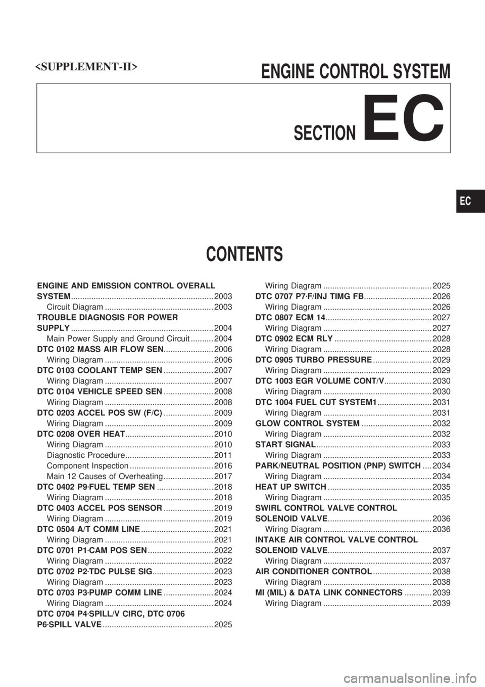
ENGINE CONTROL SYSTEM
SECTION
EC
CONTENTS
ENGINE AND EMISSION CONTROL OVERALL
SYSTEM............................................................... 2003
Circuit Diagram ................................................ 2003
TROUBLE DIAGNOSIS FOR POWER
SUPPLY............................................................... 2004
Main Power Supply and Ground Circuit .......... 2004
DTC 0102 MASS AIR FLOW SEN...................... 2006
Wiring Diagram ................................................ 2006
DTC 0103 COOLANT TEMP SEN...................... 2007
Wiring Diagram ................................................ 2007
DTC 0104 VEHICLE SPEED SEN...................... 2008
Wiring Diagram ................................................ 2008
DTC 0203 ACCEL POS SW (F/C)...................... 2009
Wiring Diagram ................................................ 2009
DTC 0208 OVER HEAT....................................... 2010
Wiring Diagram ................................................ 2010
Diagnostic Procedure....................................... 2011
Component Inspection ..................................... 2016
Main 12 Causes of Overheating ...................... 2017
DTC 0402 P9zFUEL TEMP SEN......................... 2018
Wiring Diagram ................................................ 2018
DTC 0403 ACCEL POS SENSOR...................... 2019
Wiring Diagram ................................................ 2019
DTC 0504 A/T COMM LINE................................ 2021
Wiring Diagram ................................................ 2021
DTC 0701 P1zCAM POS SEN............................. 2022
Wiring Diagram ................................................ 2022
DTC 0702 P2zTDC PULSE SIG........................... 2023
Wiring Diagram ................................................ 2023
DTC 0703 P3zPUMP COMM LINE...................... 2024
Wiring Diagram ................................................ 2024
DTC 0704 P4zSPILL/V CIRC, DTC 0706
P6zSPILL VALVE................................................. 2025Wiring Diagram ................................................ 2025
DTC 0707 P7zF/INJ TIMG FB.............................. 2026
Wiring Diagram ................................................ 2026
DTC 0807 ECM 14............................................... 2027
Wiring Diagram ................................................ 2027
DTC 0902 ECM RLY........................................... 2028
Wiring Diagram ................................................ 2028
DTC 0905 TURBO PRESSURE.......................... 2029
Wiring Diagram ................................................ 2029
DTC 1003 EGR VOLUME CONT/V..................... 2030
Wiring Diagram ................................................ 2030
DTC 1004 FUEL CUT SYSTEM1........................ 2031
Wiring Diagram ................................................ 2031
GLOW CONTROL SYSTEM............................... 2032
Wiring Diagram ................................................ 2032
START SIGNAL................................................... 2033
Wiring Diagram ................................................ 2033
PARK/NEUTRAL POSITION (PNP) SWITCH.... 2034
Wiring Diagram ................................................ 2034
HEAT UP SWITCH.............................................. 2035
Wiring Diagram ................................................ 2035
SWIRL CONTROL VALVE CONTROL
SOLENOID VALVE.............................................. 2036
Wiring Diagram ................................................ 2036
INTAKE AIR CONTROL VALVE CONTROL
SOLENOID VALVE.............................................. 2037
Wiring Diagram ................................................ 2037
AIR CONDITIONER CONTROL.......................... 2038
Wiring Diagram ................................................ 2038
MI (MIL) & DATA LINK CONNECTORS............ 2039
Wiring Diagram ................................................ 2039
EC
Page 39 of 273
When you read wiring diagrams:
+Read GI section, ªHOW TO READ WIRING DIAGRAMSº.
+See EL section, ªPOWER SUPPLY ROUTINGº for power distribution circuit.
When you perform trouble diagnoses, read GI section, ªHOW TO FOLLOW FLOW CHART IN
TROUBLE DIAGNOSESº and ªHOW TO PERFORM EFFICIENT DIAGNOSIS FOR AN ELECTRICAL
INCIDENTº.
EC-2002
Page 40 of 273

Circuit Diagram
TEC095M
ENGINE AND EMISSION CONTROL OVERALL SYSTEM
EC-2003