NISSAN PATROL 2002 Electronic Service Manual
Manufacturer: NISSAN, Model Year: 2002, Model line: PATROL, Model: NISSAN PATROL 2002Pages: 311, PDF Size: 12.08 MB
Page 41 of 311

Wiring Diagram
TEC356M
DTC 0402 P9zFUEL TEMP SENZD30DDTi
EC-3015
Page 42 of 311

Wiring Diagram
TEC357M
DTC 0403 ACCEL POS SENSORZD30DDTi
EC-3016
Page 43 of 311

Wiring Diagram
TEC358M
DTC 0902 ECM RLYZD30DDTi
EC-3017
Page 44 of 311

Wiring Diagram
TEC359M
DTC 1003 EGR VOLUME CONT/VZD30DDTi
EC-3018
Page 45 of 311

Wiring Diagram
TEC396M
MI (MIL) & DATA LINK CONNECTORSZD30DDTi
EC-3019
Page 46 of 311

MI (MIL) & DATA LINK CONNECTORSZD30DDTi
Wiring Diagram (Cont'd)
EC-3020
Page 47 of 311

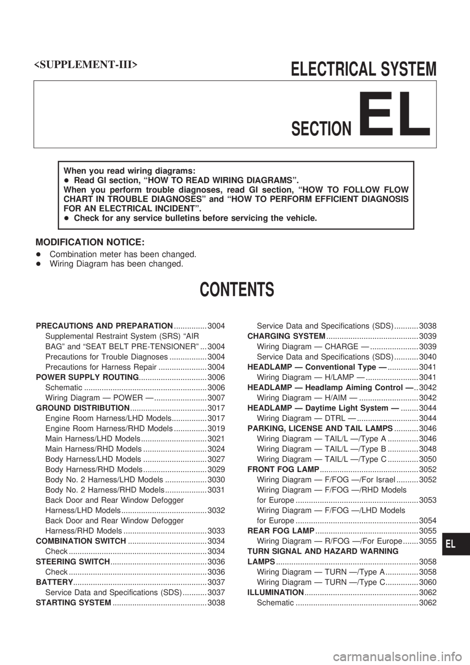
ELECTRICAL SYSTEM
SECTION
EL
When you read wiring diagrams:
+Read GI section, ªHOW TO READ WIRING DIAGRAMSº.
When you perform trouble diagnoses, read GI section, ªHOW TO FOLLOW FLOW
CHART IN TROUBLE DIAGNOSESº and ªHOW TO PERFORM EFFICIENT DIAGNOSIS
FOR AN ELECTRICAL INCIDENTº.
+Check for any service bulletins before servicing the vehicle.
MODIFICATION NOTICE:
+Combination meter has been changed.
+Wiring Diagram has been changed.
CONTENTS
PRECAUTIONS AND PREPARATION............... 3004
Supplemental Restraint System (SRS) ªAIR
BAGº and ªSEAT BELT PRE-TENSIONERº ... 3004
Precautions for Trouble Diagnoses ................. 3004
Precautions for Harness Repair ...................... 3004
POWER SUPPLY ROUTING............................... 3006
Schematic ........................................................ 3006
Wiring Diagram Ð POWER Ð ........................ 3007
GROUND DISTRIBUTION................................... 3017
Engine Room Harness/LHD Models................ 3017
Engine Room Harness/RHD Models ............... 3019
Main Harness/LHD Models .............................. 3021
Main Harness/RHD Models ............................. 3024
Body Harness/LHD Models ............................. 3027
Body Harness/RHD Models ............................. 3029
Body No. 2 Harness/LHD Models ................... 3030
Body No. 2 Harness/RHD Models ................... 3031
Back Door and Rear Window Defogger
Harness/LHD Models ....................................... 3032
Back Door and Rear Window Defogger
Harness/RHD Models ...................................... 3033
COMBINATION SWITCH.................................... 3034
Check ............................................................... 3034
STEERING SWITCH............................................ 3036
Check ............................................................... 3036
BATTERY............................................................. 3037
Service Data and Specifications (SDS) ........... 3037
STARTING SYSTEM........................................... 3038Service Data and Specifications (SDS) ........... 3038
CHARGING SYSTEM.......................................... 3039
Wiring Diagram Ð CHARGE Ð ...................... 3039
Service Data and Specifications (SDS) ........... 3040
HEADLAMP Ð Conventional Type Ð.............. 3041
Wiring Diagram Ð H/LAMP Ð ........................ 3041
HEADLAMP Ð Headlamp Aiming Control Ð.. 3042
Wiring Diagram Ð H/AIM Ð ........................... 3042
HEADLAMP Ð Daytime Light System Ð........ 3044
Wiring Diagram Ð DTRL Ð ............................ 3044
PARKING, LICENSE AND TAIL LAMPS........... 3046
Wiring Diagram Ð TAIL/L Ð/Type A .............. 3046
Wiring Diagram Ð TAIL/L Ð/Type B .............. 3048
Wiring Diagram Ð TAIL/L Ð/Type C .............. 3050
FRONT FOG LAMP............................................. 3052
Wiring Diagram Ð F/FOG Ð/For Israel .......... 3052
Wiring Diagram Ð F/FOG Ð/RHD Models
for Europe ........................................................ 3053
Wiring Diagram Ð F/FOG Ð/LHD Models
for Europe ........................................................ 3054
REAR FOG LAMP............................................... 3055
Wiring Diagram Ð R/FOG Ð/For Europe ....... 3055
TURN SIGNAL AND HAZARD WARNING
LAMPS................................................................. 3058
Wiring Diagram Ð TURN Ð/Type A ............... 3058
Wiring Diagram Ð TURN Ð/Type C............... 3060
ILLUMINATION.................................................... 3062
Schematic ........................................................ 3062
EL
Page 48 of 311

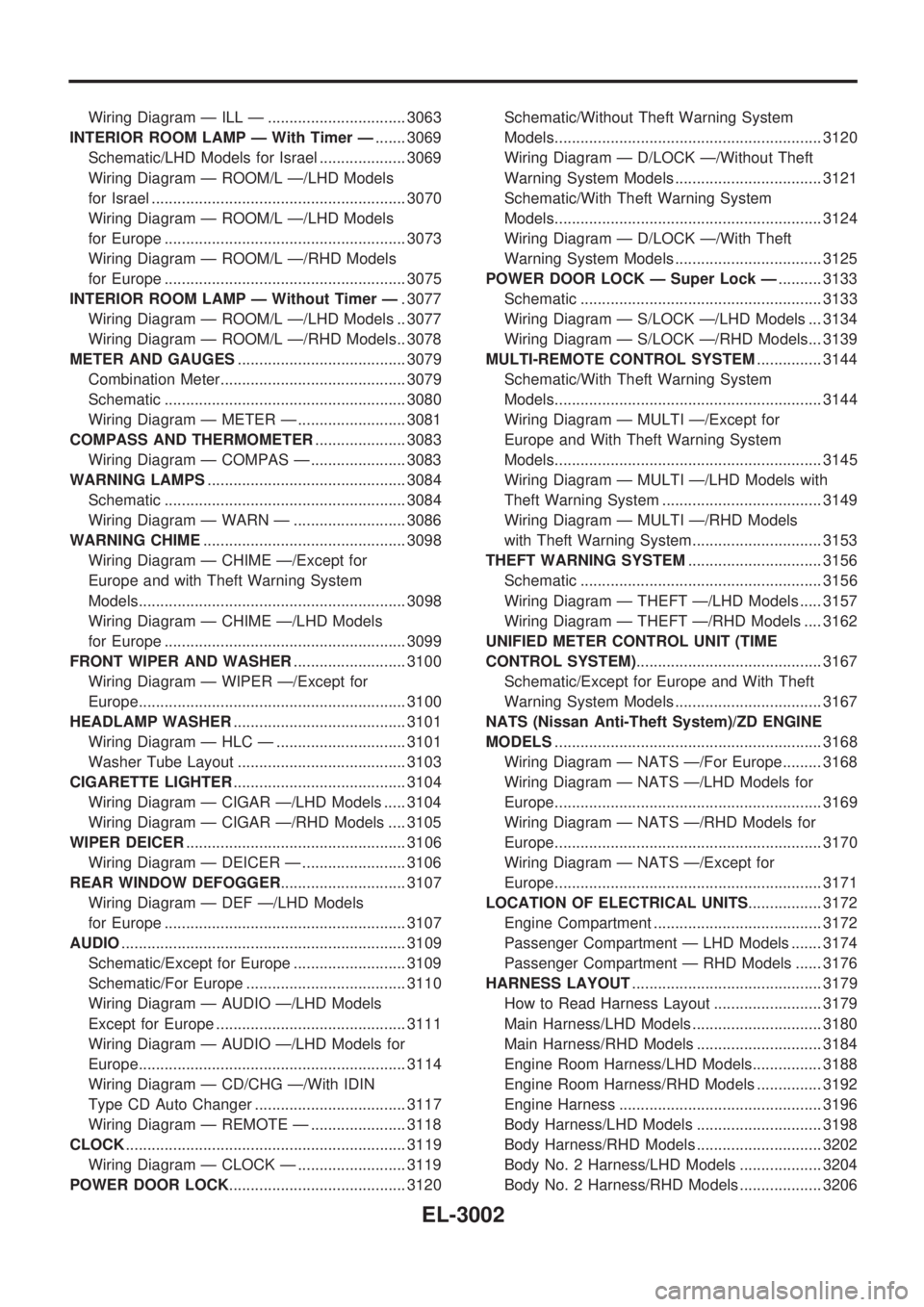
Wiring Diagram Ð ILL Ð ................................ 3063
INTERIOR ROOM LAMP Ð With Timer Ð....... 3069
Schematic/LHD Models for Israel .................... 3069
Wiring Diagram Ð ROOM/L Ð/LHD Models
for Israel ........................................................... 3070
Wiring Diagram Ð ROOM/L Ð/LHD Models
for Europe ........................................................ 3073
Wiring Diagram Ð ROOM/L Ð/RHD Models
for Europe ........................................................ 3075
INTERIOR ROOM LAMP Ð Without Timer Ð. 3077
Wiring Diagram Ð ROOM/L Ð/LHD Models .. 3077
Wiring Diagram Ð ROOM/L Ð/RHD Models.. 3078
METER AND GAUGES....................................... 3079
Combination Meter........................................... 3079
Schematic ........................................................ 3080
Wiring Diagram Ð METER Ð ......................... 3081
COMPASS AND THERMOMETER..................... 3083
Wiring Diagram Ð COMPAS Ð ...................... 3083
WARNING LAMPS.............................................. 3084
Schematic ........................................................ 3084
Wiring Diagram Ð WARN Ð .......................... 3086
WARNING CHIME............................................... 3098
Wiring Diagram Ð CHIME Ð/Except for
Europe and with Theft Warning System
Models.............................................................. 3098
Wiring Diagram Ð CHIME Ð/LHD Models
for Europe ........................................................ 3099
FRONT WIPER AND WASHER.......................... 3100
Wiring Diagram Ð WIPER Ð/Except for
Europe.............................................................. 3100
HEADLAMP WASHER........................................ 3101
Wiring Diagram Ð HLC Ð .............................. 3101
Washer Tube Layout ....................................... 3103
CIGARETTE LIGHTER........................................ 3104
Wiring Diagram Ð CIGAR Ð/LHD Models ..... 3104
Wiring Diagram Ð CIGAR Ð/RHD Models .... 3105
WIPER DEICER................................................... 3106
Wiring Diagram Ð DEICER Ð ........................ 3106
REAR WINDOW DEFOGGER............................. 3107
Wiring Diagram Ð DEF Ð/LHD Models
for Europe ........................................................ 3107
AUDIO.................................................................. 3109
Schematic/Except for Europe .......................... 3109
Schematic/For Europe ..................................... 3110
Wiring Diagram Ð AUDIO Ð/LHD Models
Except for Europe ............................................ 3111
Wiring Diagram Ð AUDIO Ð/LHD Models for
Europe.............................................................. 3114
Wiring Diagram Ð CD/CHG Ð/With IDIN
Type CD Auto Changer ................................... 3117
Wiring Diagram Ð REMOTE Ð ...................... 3118
CLOCK................................................................. 3119
Wiring Diagram Ð CLOCK Ð ......................... 3119
POWER DOOR LOCK......................................... 3120Schematic/Without Theft Warning System
Models.............................................................. 3120
Wiring Diagram Ð D/LOCK Ð/Without Theft
Warning System Models .................................. 3121
Schematic/With Theft Warning System
Models.............................................................. 3124
Wiring Diagram Ð D/LOCK Ð/With Theft
Warning System Models .................................. 3125
POWER DOOR LOCK Ð Super Lock Ð.......... 3133
Schematic ........................................................ 3133
Wiring Diagram Ð S/LOCK Ð/LHD Models ... 3134
Wiring Diagram Ð S/LOCK Ð/RHD Models... 3139
MULTI-REMOTE CONTROL SYSTEM............... 3144
Schematic/With Theft Warning System
Models.............................................................. 3144
Wiring Diagram Ð MULTI Ð/Except for
Europe and With Theft Warning System
Models.............................................................. 3145
Wiring Diagram Ð MULTI Ð/LHD Models with
Theft Warning System ..................................... 3149
Wiring Diagram Ð MULTI Ð/RHD Models
with Theft Warning System.............................. 3153
THEFT WARNING SYSTEM............................... 3156
Schematic ........................................................ 3156
Wiring Diagram Ð THEFT Ð/LHD Models ..... 3157
Wiring Diagram Ð THEFT Ð/RHD Models .... 3162
UNIFIED METER CONTROL UNIT (TIME
CONTROL SYSTEM)........................................... 3167
Schematic/Except for Europe and With Theft
Warning System Models .................................. 3167
NATS (Nissan Anti-Theft System)/ZD ENGINE
MODELS.............................................................. 3168
Wiring Diagram Ð NATS Ð/For Europe......... 3168
Wiring Diagram Ð NATS Ð/LHD Models for
Europe.............................................................. 3169
Wiring Diagram Ð NATS Ð/RHD Models for
Europe.............................................................. 3170
Wiring Diagram Ð NATS Ð/Except for
Europe.............................................................. 3171
LOCATION OF ELECTRICAL UNITS................. 3172
Engine Compartment ....................................... 3172
Passenger Compartment Ð LHD Models ....... 3174
Passenger Compartment Ð RHD Models ...... 3176
HARNESS LAYOUT............................................ 3179
How to Read Harness Layout ......................... 3179
Main Harness/LHD Models .............................. 3180
Main Harness/RHD Models ............................. 3184
Engine Room Harness/LHD Models................ 3188
Engine Room Harness/RHD Models ............... 3192
Engine Harness ............................................... 3196
Body Harness/LHD Models ............................. 3198
Body Harness/RHD Models ............................. 3202
Body No. 2 Harness/LHD Models ................... 3204
Body No. 2 Harness/RHD Models ................... 3206
EL-3002
Page 49 of 311

Chassis Harness .............................................. 3208
Back Door Harness and Rear Window
Defogger Harness ............................................ 3209
WIRING DIAGRAM CODES (CELL CODES) ..... 3210
Wiring Diagram Codes (Cell Codes) ............... 3210
EL-3003
Page 50 of 311

Supplemental Restraint System (SRS) ªAIR
BAGº and ªSEAT BELT PRE-TENSIONERº
The Supplemental Restraint System such as ªAIR BAGº and ªSEAT BELT PRE-TENSIONERº used along
with a seat belt, helps to reduce the risk or severity of injury to the driver and front passenger for certain
types of collision. The SRS system composition which is available to NISSAN MODEL Y61 is as follows (The
composition varies according to the destination and optional equipment.):
+For a frontal collision
The Supplemental Restraint System consists of driver air bag module (located in the center of the
steering wheel), front passenger air bag module (located on the instrument panel on passenger side),
seat belt pre-tensioners, a diagnosis sensor unit, warning lamp, wiring harness and spiral cable.
+For a side collision
The Supplemental Restraint System consists of front side air bag module (located in the outer side of
front seat), satellite sensor, diagnosis sensor unit (one of components of air bags for a frontal collision),
wiring harness, warning lamp (one of components of air bags for a frontal collision).
Information necessary to service the system safely is included in theRS sectionof this Service Manual.
WARNING:
+To avoid rendering the SRS inoperative, which could increase the risk of personal injury or death
in the event of a collision which would result in air bag inflation, all maintenance should be per-
formed by an authorized NISSAN dealer.
+Improper maintenance, including incorrect removal and installation of the SRS, can lead to per-
sonal injury caused by unintentional activation of the system. For removal of Spiral Cable and
Air Bag Module, see the RS section.
+Do not use electrical test equipment on any circuit related to the SRS unless instructed to in this
Service Manual. SRS wiring harnesses can be identified by yellow harness connector.
Precautions for Trouble Diagnoses
CAN SYSTEM
+Do not apply voltage of 7.0V or higher to the measure-
ment terminals.
+Use the tester with its open terminal voltage being 7.0V
or less.
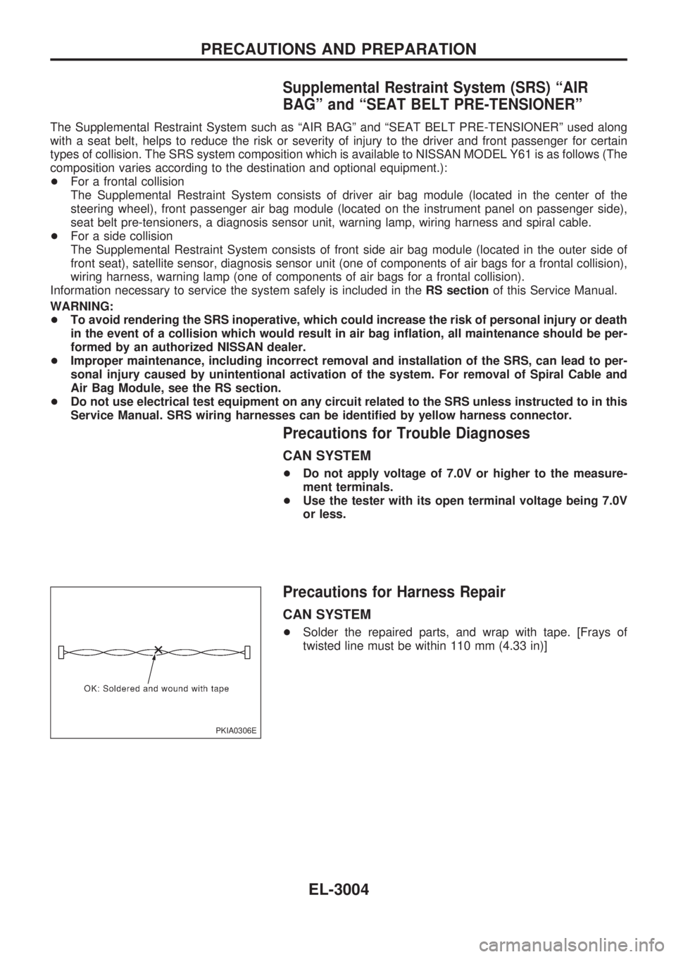
Precautions for Harness Repair
CAN SYSTEM
+Solder the repaired parts, and wrap with tape. [Frays of
twisted line must be within 110 mm (4.33 in)]
PKIA0306E
PRECAUTIONS AND PREPARATION
EL-3004