Condition NISSAN PATROL 2004 Electronic Owner's Manual
[x] Cancel search | Manufacturer: NISSAN, Model Year: 2004, Model line: PATROL, Model: NISSAN PATROL 2004Pages: 579, PDF Size: 26.61 MB
Page 257 of 579
System Description
OUTLINE
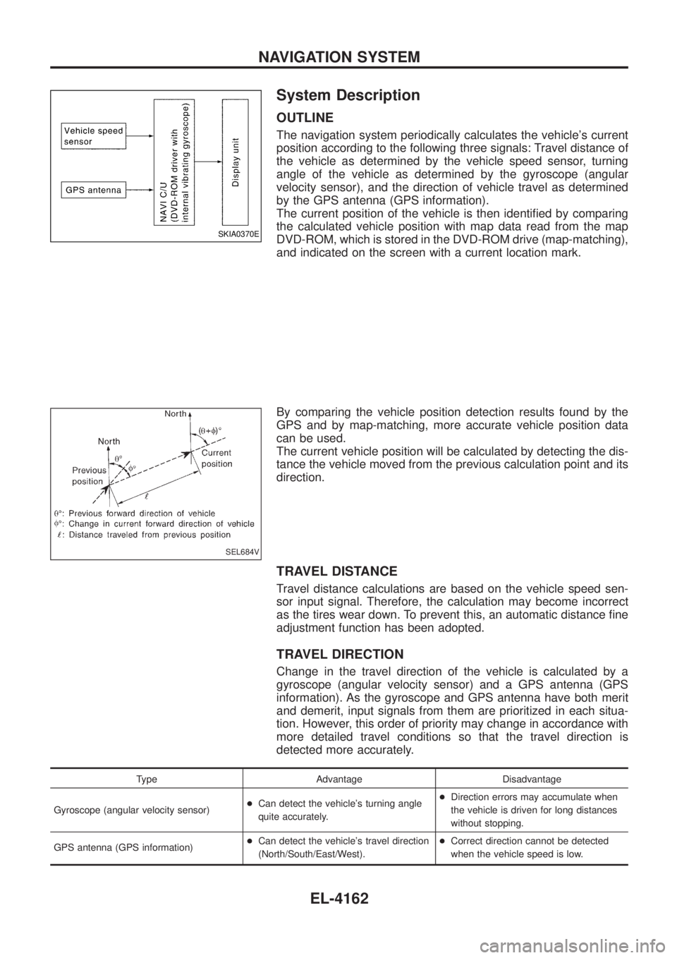
The navigation system periodically calculates the vehicle's current
position according to the following three signals: Travel distance of
the vehicle as determined by the vehicle speed sensor, turning
angle of the vehicle as determined by the gyroscope (angular
velocity sensor), and the direction of vehicle travel as determined
by the GPS antenna (GPS information).
The current position of the vehicle is then identi®ed by comparing
the calculated vehicle position with map data read from the map
DVD-ROM, which is stored in the DVD-ROM drive (map-matching),
and indicated on the screen with a current location mark.
By comparing the vehicle position detection results found by the
GPS and by map-matching, more accurate vehicle position data
can be used.
The current vehicle position will be calculated by detecting the dis-
tance the vehicle moved from the previous calculation point and its
direction.
TRAVEL DISTANCE
Travel distance calculations are based on the vehicle speed sen-
sor input signal. Therefore, the calculation may become incorrect
as the tires wear down. To prevent this, an automatic distance ®ne
adjustment function has been adopted.
TRAVEL DIRECTION
Change in the travel direction of the vehicle is calculated by a
gyroscope (angular velocity sensor) and a GPS antenna (GPS
information). As the gyroscope and GPS antenna have both merit
and demerit, input signals from them are prioritized in each situa-
tion. However, this order of priority may change in accordance with
more detailed travel conditions so that the travel direction is
detected more accurately.
Type Advantage Disadvantage
Gyroscope (angular velocity sensor) +
Can detect the vehicle's turning angle
quite accurately. +
Direction errors may accumulate when
the vehicle is driven for long distances
without stopping.
GPS antenna (GPS information) +
Can detect the vehicle's travel direction
(North/South/East/West). +
Correct direction cannot be detected
when the vehicle speed is low.
SKIA0370E
SEL684V
NAVIGATION SYSTEM
EL-4162
Page 259 of 579
GPS (GLOBAL POSITIONING SYSTEM)
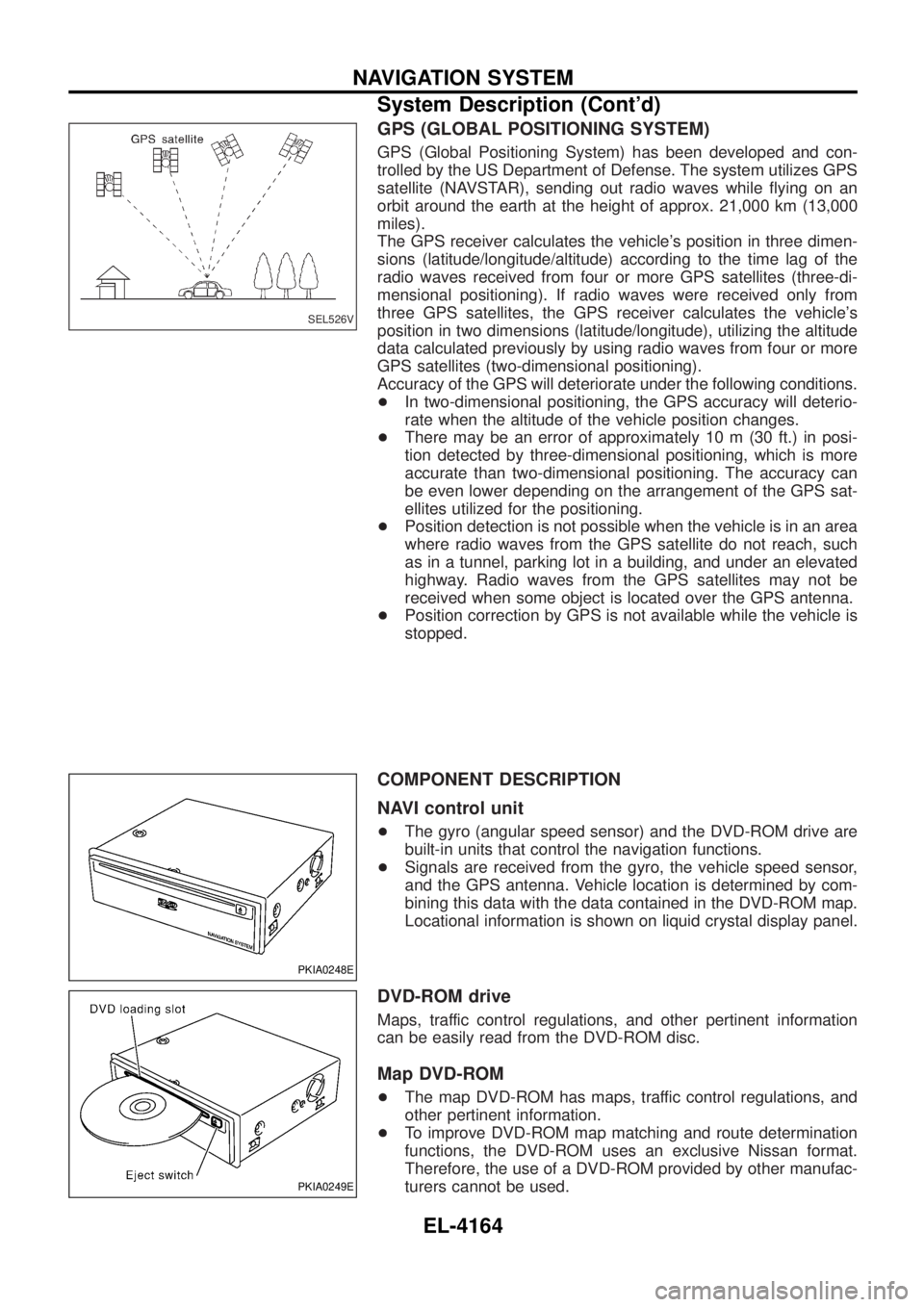
GPS (Global Positioning System) has been developed and con-
trolled by the US Department of Defense. The system utilizes GPS
satellite (NAVSTAR), sending out radio waves while ¯ying on an
orbit around the earth at the height of approx. 21,000 km (13,000
miles).
The GPS receiver calculates the vehicle's position in three dimen-
sions (latitude/longitude/altitude) according to the time lag of the
radio waves received from four or more GPS satellites (three-di-
mensional positioning). If radio waves were received only from
three GPS satellites, the GPS receiver calculates the vehicle's
position in two dimensions (latitude/longitude), utilizing the altitude
data calculated previously by using radio waves from four or more
GPS satellites (two-dimensional positioning).
Accuracy of the GPS will deteriorate under the following conditions.
+In two-dimensional positioning, the GPS accuracy will deterio-
rate when the altitude of the vehicle position changes.
+ There may be an error of approximately 10 m (30 ft.) in posi-
tion detected by three-dimensional positioning, which is more
accurate than two-dimensional positioning. The accuracy can
be even lower depending on the arrangement of the GPS sat-
ellites utilized for the positioning.
+ Position detection is not possible when the vehicle is in an area
where radio waves from the GPS satellite do not reach, such
as in a tunnel, parking lot in a building, and under an elevated
highway. Radio waves from the GPS satellites may not be
received when some object is located over the GPS antenna.
+ Position correction by GPS is not available while the vehicle is
stopped.
COMPONENT DESCRIPTION
NAVI control unit
+The gyro (angular speed sensor) and the DVD-ROM drive are
built-in units that control the navigation functions.
+ Signals are received from the gyro, the vehicle speed sensor,
and the GPS antenna. Vehicle location is determined by com-
bining this data with the data contained in the DVD-ROM map.
Locational information is shown on liquid crystal display panel.
DVD-ROM drive
Maps, traffic control regulations, and other pertinent information
can be easily read from the DVD-ROM disc.
Map DVD-ROM
+The map DVD-ROM has maps, traffic control regulations, and
other pertinent information.
+ To improve DVD-ROM map matching and route determination
functions, the DVD-ROM uses an exclusive Nissan format.
Therefore, the use of a DVD-ROM provided by other manufac-
turers cannot be used.
SEL526V
PKIA0248E
PKIA0249E
NAVIGATION SYSTEM
System Description (Cont'd)
EL-4164
Page 260 of 579
Gyro (Angular speed sensor)
+The oscillator gyro sensor is used to detect changes in vehicle
steering angle.
+ The gyro is built into the navigation (NAVI) control unit.
BIRDVIEW T
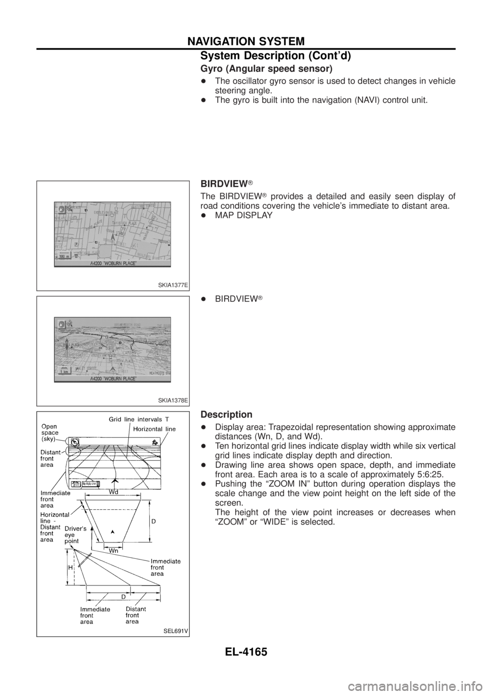
The BIRDVIEW Tprovides a detailed and easily seen display of
road conditions covering the vehicle's immediate to distant area.
+ MAP DISPLAY
+ BIRDVIEW T
Description
+Display area: Trapezoidal representation showing approximate
distances (Wn, D, and Wd).
+ Ten horizontal grid lines indicate display width while six vertical
grid lines indicate display depth and direction.
+ Drawing line area shows open space, depth, and immediate
front area. Each area is to a scale of approximately 5:6:25.
+ Pushing the ªZOOM INº button during operation displays the
scale change and the view point height on the left side of the
screen.
The height of the view point increases or decreases when
ªZOOMº or ªWIDEº is selected.
SKIA1377E
SKIA1378E
SEL691V
NAVIGATION SYSTEM
System Description (Cont'd)
EL-4165
Page 261 of 579
MAP DISPLAY
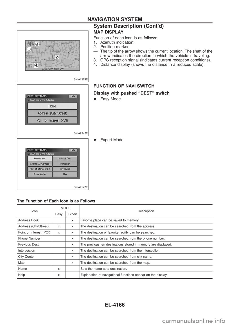
Function of each icon is as follows:
1. Azimuth indication.
2. Position marker.
Ð The tip of the arrow shows the current location. The shaft of thearrow indicates the direction in which the vehicle is traveling.
3. GPS reception signal (indicates current reception conditions).
4. Distance display (shows the distance in a reduced scale).
FUNCTION OF NAVI SWITCH
Display with pushed ªDESTº switch
+ Easy Mode
+ Expert Mode
The Function of Each Icon Is as Follows:
Icon MODE
Description
Easy Expert
Address Book x Favorite place can be saved to memory.
Address (City/Street) x x The destination can be searched from the address.
Point of Interest (POI) x x The destination of favorite facility can be searched.
Phone Number x The destination can be searched from the phone number.
Previous Dest. x The previous ten destinations stored in memory are displayed.
Intersection x The destination can be searched from the intersection.
City Center x The destination can be searched from city name.
Map x The destination can be searched from the map.
Home x Sets the home as a destination.
Help x Explanation of navigational functions appear on the display.
SKIA1379E
SKIA9542E
SKIA9142E
NAVIGATION SYSTEM
System Description (Cont'd)
EL-4166
Page 264 of 579
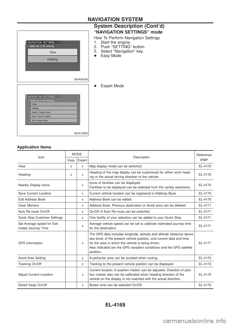
ªNAVIGATION SETTINGSº mode
How To Perform Navigation Settings
1. Start the engine.
2. Push ªSETTINGº button.
3. Select ªNavigationº key.
+Easy Mode
+ Expert Mode
Application Items
Icon MODE
Description Reference
page
Easy Expert
View x x Map display mode can be switched. EL-4170
Heading x x Heading of the map display can be customized for either north head-
ing or the actual driving direction of the vehicle. EL-4170
Nearby Display Icons x Icons of facilities can be displayed.
Facilities to be displayed can be selected from the variety selections. EL-4170
Save Current Location x Current vehicle location can be registered in Address Book. EL-4170
Edit Address Book x Address Book can be edited. EL-4170
Clear Memory x Address Book, Previous destination or Avoid area can be deleted. EL-4171
Auto Re-route On/Off x On/Off of Auto Re-route can be switched. EL-4171
Quick Stop Customer Settings x One facility of your selection can be added to your Quick Stop. EL-4171
Set Average speed for Esti-
mated Journey Time xAverage vehicle speed can be set to calibrate estimated journey time
for the destination. EL-4171
GPS Information x The GPS data includes longitude, latitude and altitude (distance above
sea level) of the present vehicle position, and current date and time
for the area in which the vehicle is being driven.
Also indicated are the GPS reception conditions and the GPS satellite
position. EL-4171
Avoid Area Setting x A particular area can be avoided when routing. EL-4172
Tracking On/Off x Tracking to the present vehicle position can be displayed. EL-4172
Adjust Current Location x Current location of position marker can be adjusted. Direction of posi-
tion marker also can be calibrated when heading direction of the
vehicle on the display is not matched with the actual direction. EL-4172
Switch beep On/Off x Button tone can be selected On/Off. EL-4172
SKIA9543E
SKIA1385E
NAVIGATION SYSTEM
System Description (Cont'd)
EL-4169
Page 278 of 579
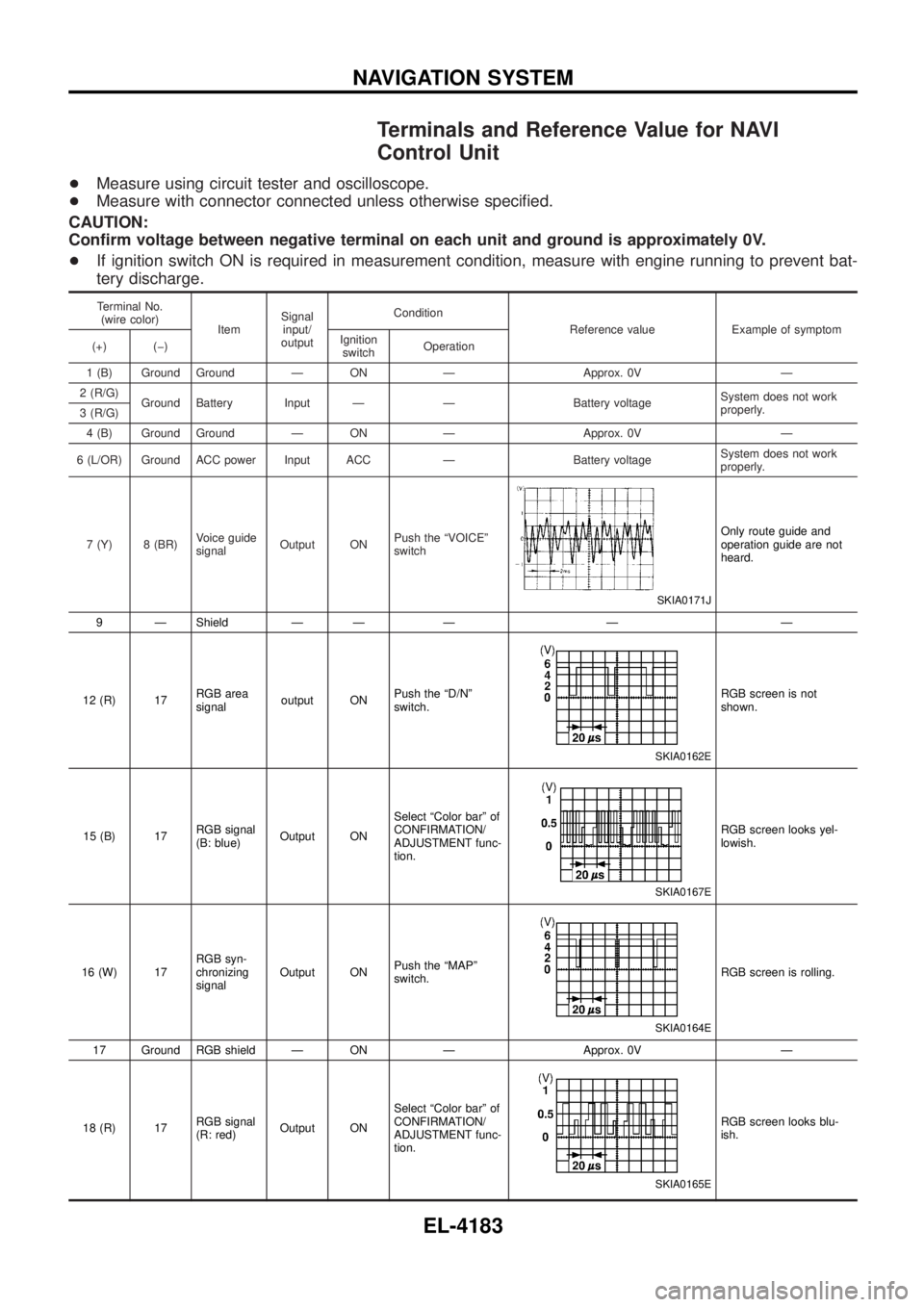
Terminals and Reference Value for NAVI
Control Unit
+Measure using circuit tester and oscilloscope.
+ Measure with connector connected unless otherwise speci®ed.
CAUTION:
Con®rm voltage between negative terminal on each unit and ground is approximately 0V.
+ If ignition switch ON is required in measurement condition, measure with engine running to prevent bat-
tery discharge.
Terminal No.
(wire color) ItemSignal
input/
output Condition
Reference value Example of symptom
(+) (þ) Ignition
switch Operation
1 (B) Ground Ground Ð ON Ð Approx. 0V Ð
2 (R/G) Ground Battery Input Ð Ð Battery voltage System does not work
properly.
3 (R/G)
4 (B) Ground Ground Ð ON Ð Approx. 0V Ð
6 (L/OR) Ground ACC power Input ACC Ð Battery voltage System does not work
properly.
7 (Y) 8 (BR) Voice guide
signalOutput ON Push the ªVOICEº
switch
SKIA0171J
Only route guide and
operation guide are not
heard.
9 Ð Shield Ð Ð Ð Ð Ð
12 (R) 17 RGB area
signaloutput ON Push the ªD/Nº
switch.
SKIA0162E
RGB screen is not
shown.
15 (B) 17 RGB signal
(B: blue)Output ON Select ªColor barº of
CONFIRMATION/
ADJUSTMENT func-
tion.
SKIA0167E
RGB screen looks yel-
lowish.
16 (W) 17 RGB syn-
chronizing
signalOutput ON
Push the ªMAPº
switch.
SKIA0164E
RGB screen is rolling.
17 Ground RGB shield Ð ON Ð Approx. 0V Ð
18 (R) 17 RGB signal
(R: red)Output ON Select ªColor barº of
CONFIRMATION/
ADJUSTMENT func-
tion.
SKIA0165E
RGB screen looks blu-
ish.
NAVIGATION SYSTEM
EL-4183
Page 279 of 579

Terminal No.(wire color) ItemSignal
input/
output Condition
Reference value Example of symptom
(+) (þ) Ignition
switch Operation
21 (G) 17 RGB signal
(G: green)Output ON Select ªColor barº of
CONFIRMATION/
ADJUSTMENT func-
tion.
SKIA0166E
RGB screen looks red-
dish.
25 (L/B) Ground Illumination
signalInput ON Lighting switch posi-
tion 1st or 2nd
Battery voltage
Night illumination for
switches does not illumi-
nate.
Lighting switch posi-
tion OFF Approx. 0V
26 (R/W) Ground IGN signal Input ON Ð Battery voltage Vehicle information set-
ting is not possible.
27 (Y) Ground Reverse
signalInput ON Select R-position Battery voltage
The navigation current
location mark moves
strangely when the
vehicle is moving back-
wards.
Other position Approx. 0V
28 (R/W) Ground Vehicle
speed signalInput ON When vehicle speed
is approx. 40 km/h
(25 MPH)
ELF1084D
Navigation current loca-
tion mark does not indi-
cate the correct position.
43 Ð Shield Ð Ð Ð Ð Ð
44 (W) 43 Communica-
tion signal
(+)Input/
Output ON Ð
SKIA0175E
System does not work
properly.
45 (B) 43 Communica-
tion signal
(Ð)Input/
Output ON Ð
SKIA0176E
System does not work
properly
49 Ground GPS
antenna sig-
nalInput ON
Connector is not
connected. Approx. 5VGPS correction is not
possible.
50 Ð Shield Ð Ð Ð Ð Ð
NAVIGATION SYSTEM
Terminals and Reference Value for NAVI
Control Unit (Cont'd)
EL-4184
Page 280 of 579

Terminals and Reference Value for Display
Terminal No.(wire color) ItemSignal
input/
output Condition
Reference value Example of symptom
(+) (þ) Ignition
switch Operation
1 (R) 4 RGB signal
(R: red)Input ON Select ªColor barº of
CONFIRMATION/
ADJUSTMENT func-
tion.
SKIA0165E
RGB screen looks blu-
ish.
2 (G) 4 RGB signal
(G: green)Input ON Select ªColor barº of
CONFIRMATION/
ADJUSTMENT func-
tion.
SKIA0166E
RGB screen looks red-
dish.
3 (B) 4 RGB signal
(B: blue)Input ON Select ªColor barº of
CONFIRMATION/
ADJUSTMENT func-
tion.
SKIA0167E
RGB screen looks yel-
lowish.
4 Ð Shield Ð Ð Ð Ð Ð
7 (W) 4 RGB syn-
chronizing
signalInput ON
Push the ªMAPº
switch.
SKIA0164E
RGB screen is rolling.
8 (R) Ground RGB area
signalInput ON Push the ªD/Nº
switch.
SKIA0162E
RGB screen is not
shown.
15 (OR) Ground Communica-
tion signal
(DISP-SW)Output ON
Push the ªINFOº
switch.
SKIA0835E
System does not work
properly.
16 (B) 17 Communica-
tion signal
(NAVI-DISP)Input ON
Push the ªINFOº
switch.
SKIA0832E
System does not work
properly.
NAVIGATION SYSTEM
EL-4185
Page 281 of 579
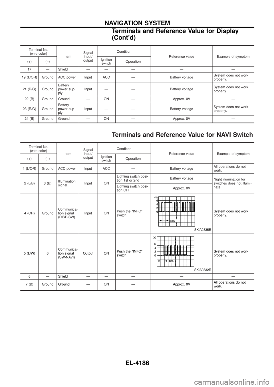
Terminal No.(wire color) ItemSignal
input/
output Condition
Reference value Example of symptom
(+) (þ) Ignition
switch Operation
17 Ð Shield Ð Ð Ð Ð Ð
19 (L/OR) Ground ACC power Input ACC Ð Battery voltage System does not work
properly.
21 (R/G) Ground Battery
power sup-
plyInput Ð Ð Battery voltage
System does not work
properly.
22 (B) Ground Ground Ð ON Ð Approx. 0V Ð
23 (R/G) Ground Battery
power sup-
plyInput Ð Ð Battery voltage
System does not work
properly.
24 (B) Ground Ground Ð ON Ð Approx. 0V Ð
Terminals and Reference Value for NAVI Switch
Terminal No. (wire color) ItemSignal
input/
output Condition
Reference value Example of symptom
(+) (þ) Ignition
switch Operation
1 (L/OR) Ground ACC power Input ACC Ð Battery voltage All operations do not
work.
2 (L/B) 3 (B) Illumination
signalInput ON Lighting switch posi-
tion 1st or 2nd
Battery voltage
Night illumination for
switches does not illumi-
nate.
Lighting switch posi-
tion OFF Approx. 0V
4 (OR) Ground Communica-
tion signal
(DISP-SW)Input ON
Push the ªINFOº
switch
SKIA0835E
System does not work
properly.
5 (L/W) 6 Communica-
tion signal
(SW-NAVI)Output ON
Push the ªINFOº
switch
SKIA0832E
System does not work
properly.
6 Ð Shield Ð Ð Ð Ð Ð
7 (B) Ground Ground Ð ON Ð Approx. 0V All operations do not
work.
NAVIGATION SYSTEM
Terminals and Reference Value for Display
(Cont'd)
EL-4186
Page 282 of 579
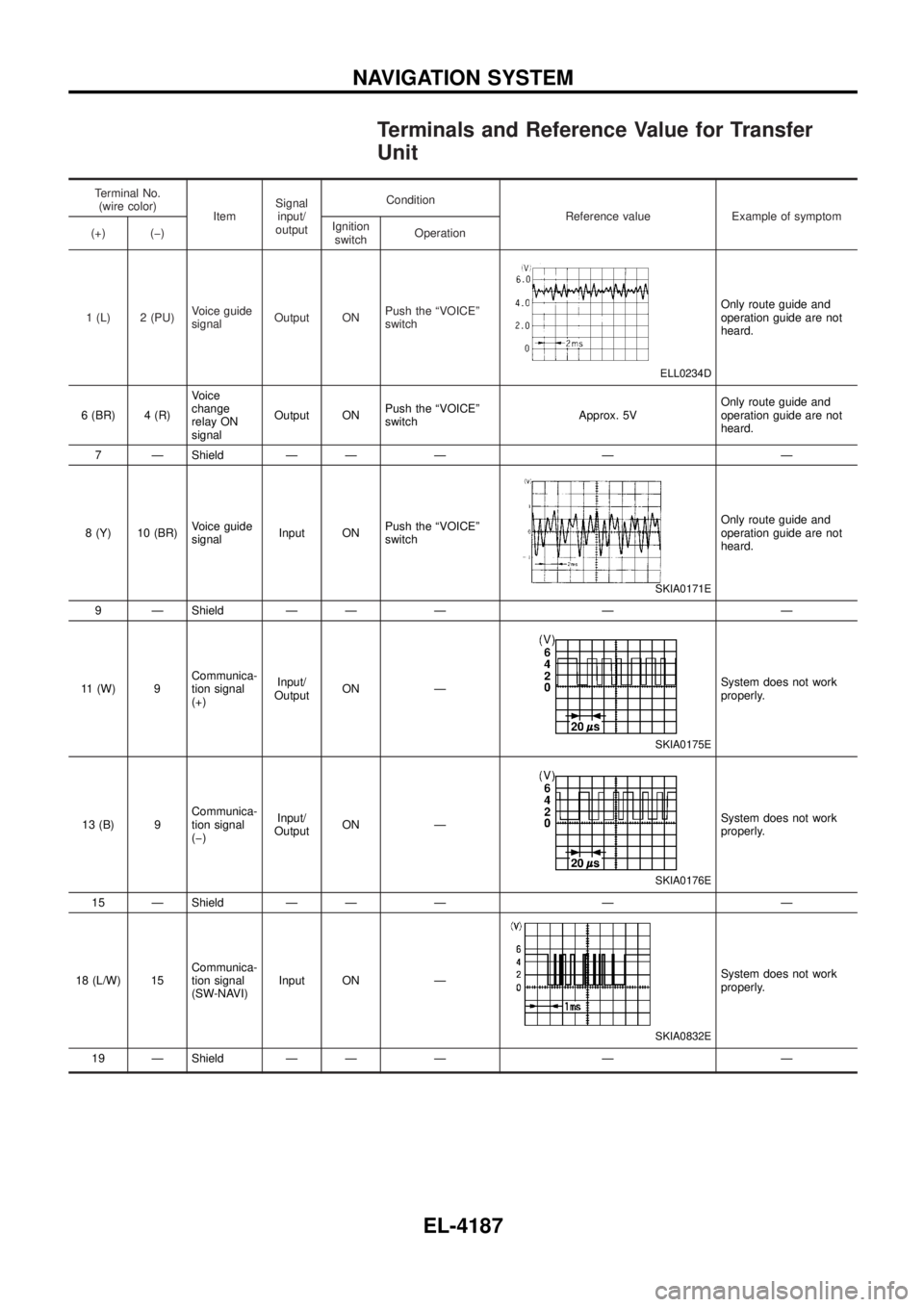
Terminals and Reference Value for Transfer
Unit
Terminal No.(wire color) ItemSignal
input/
output Condition
Reference value Example of symptom
(+) (þ) Ignition
switch Operation
1 (L) 2 (PU) Voice guide
signalOutput ON Push the ªVOICEº
switch
ELL0234D
Only route guide and
operation guide are not
heard.
6 (BR) 4 (R) Voice
change
relay ON
signalOutput ON
Push the ªVOICEº
switch Approx. 5VOnly route guide and
operation guide are not
heard.
7 Ð Shield Ð Ð Ð Ð Ð
8 (Y) 10 (BR) Voice guide
signalInput ON Push the ªVOICEº
switch
SKIA0171E
Only route guide and
operation guide are not
heard.
9 Ð Shield Ð Ð Ð Ð Ð
11 (W) 9 Communica-
tion signal
(+)Input/
Output ON Ð
SKIA0175E
System does not work
properly.
13 (B) 9 Communica-
tion signal
(þ)Input/
Output ON Ð
SKIA0176E
System does not work
properly.
15 Ð Shield Ð Ð Ð Ð Ð
18 (L/W) 15 Communica-
tion signal
(SW-NAVI)Input ON Ð
SKIA0832E
System does not work
properly.
19 Ð Shield Ð Ð Ð Ð Ð
NAVIGATION SYSTEM
EL-4187