NISSAN PATROL 2004 Electronic Repair Manual
Manufacturer: NISSAN, Model Year: 2004, Model line: PATROL, Model: NISSAN PATROL 2004Pages: 579, PDF Size: 26.61 MB
Page 441 of 579

Back Door Harness and Rear Window Defogger
Harness
TEL109V
HARNESS LAYOUT/WAGON AND HARDTOP MODELS
EL-4346
Page 442 of 579

Wiring Diagram Codes (Cell Codes)
Use the chart below to ®nd out what each wiring diagram code
stands for.
Refer to the wiring diagram code in the alphabetical index to ®nd
the location (Page number) of each wiring diagram.
Code Section Wiring Diagram Name
A/C, A HA Auto Air Conditioner
A/C, M HA Manual Air Conditioner
A/CCUT EC Air Conditioner Control
A/T AT A/T
ASCD EL Automatic Speed Control Device
AUDIO EL Audio
BACK/L EL Back-up Lamp
CD/CHG EL CD Auto Changer
CHIME EL Warning Chime
COMPAS EL Compass and Thermometer
COOL/B HA Cool Box
D/LOCK EL Power Door Lock
DEF EL Rear Window Defogger
DEICER EL Wiper Deicer
DTRL EL Headlamp Ð Daytime Light System
F/FOG EL Front Fog Lamp
FICD EC IACV-FICD Solenoid Valve
GLOW EC Quick Glow System
H/AIM EL Headlamp Aiming Control System
H/LAMP EL Headlamp
HEATUP EC Heat Up Switch
HLC EL Headlamp Washer
HORN EL Horn
HSEAT EL Heated Seat
ILL EL Illumination
LOAD EC Electrical Load Signal
MAFS EC Mass Air Flow Sensor
METER EL Meter and Gauges
MIRROR EL Door Mirror
MULTI EL Multi-remote Control System
NATS EL Nissan Anti-Theft System
NAVI EL Navigation System
NONDTC AT Non-detective Items
P/ANT EL Power Antenna
PHONE EL Telephone
POWER EL Power Supply Routing
R/COOL HA Rear Cooler System
R/FOG EL Rear Fog LampCode Section Wiring Diagram Name
R/HEAT HA Rear Heater System
REMOTE EL Audio (Remote Control Switch)
ROOM/L EL Interior Room Lamp
S/LOCK EL Power Door Lock Ð Super Lock
S/TANK FE Sub Fuel Tank Control System
SRS RS Supplemental Restraint System
STAB RA Stabilizer Release Device
STOP/L EL Stop Lamp
TAIL/L EL Parking, License and Tail Lamps
THEFT EL Theft Warning System
TRQ/SG EC Engine Torque Control Signal
TURN EL Turn Signal and Hazard Warning
Lamps
VSS EC Vehicle Speed Sensor
WARN EL Warning Lamps
WINDOW EL Power Window
WIP/R EL Rear Wiper and Washer
WIPER EL Front Wiper and Washer
WIRING DIAGRAM CODES (CELL CODES)
EL-4347
Page 443 of 579
SECTION
EM
MODIFICATION NOTICE:
+ Valve lifter of ZD30DDTi engine has been changed from a type without shim to a type with adjusting shim.
CONTENTS
PREPARATION ..........................................................4002
Special Service Tools ............................................4002
ZD
CAMSHAFT...............................................................4003
Removal and Installation .......................................4003
Inspection...............................................................4003
VALVE CLEARANCE INSPECTIONS AND
ADJUSTMENTS .........................................................4005 Adjustments ...........................................................4005
TIMING GEAR ...........................................................4008
Removal and Installation .......................................4008
Removal .................................................................4009
Installation ..............................................................4012
CYLINDER HEAD ......................................................4016
Disassembly and Assembly ...................................4016
SERVICE DATA AND SPECIFICATIONS (SDS) ......4017
Valve ......................................................................4017
EM-4001
Page 444 of 579
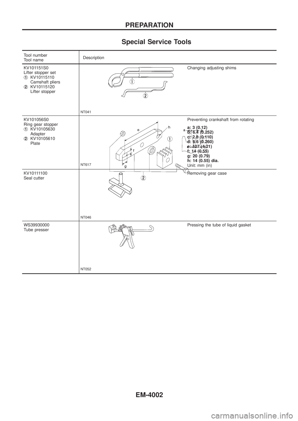
Special Service Tools
Tool number
Tool nameDescription
KV101151S0
Lifter stopper set
j
1KV10115110
Camshaft pliers
j
2KV10115120
Lifter stopper
NT041
Changing adjusting shims
KV101056S0
Ring gear stopper
j
1KV10105630
Adapter
j
2KV10105610
Plate
NT617
Preventing crankshaft from rotating
a: 3 (0.12)
b: 6.4 (0.252)
c: 2.8 (0.110)
d: 6.6 (0.260)
e: 107 (4.21)
f: 14 (0.55)
g: 20 (0.79)
h: 14 (0.55) dia.
Unit: mm (in)
KV101111 0 0
Seal cutter
NT046
Removing gear case
WS39930000
Tube presser
NT052
Pressing the tube of liquid gasket
PREPARATION
EM-4002
Page 445 of 579
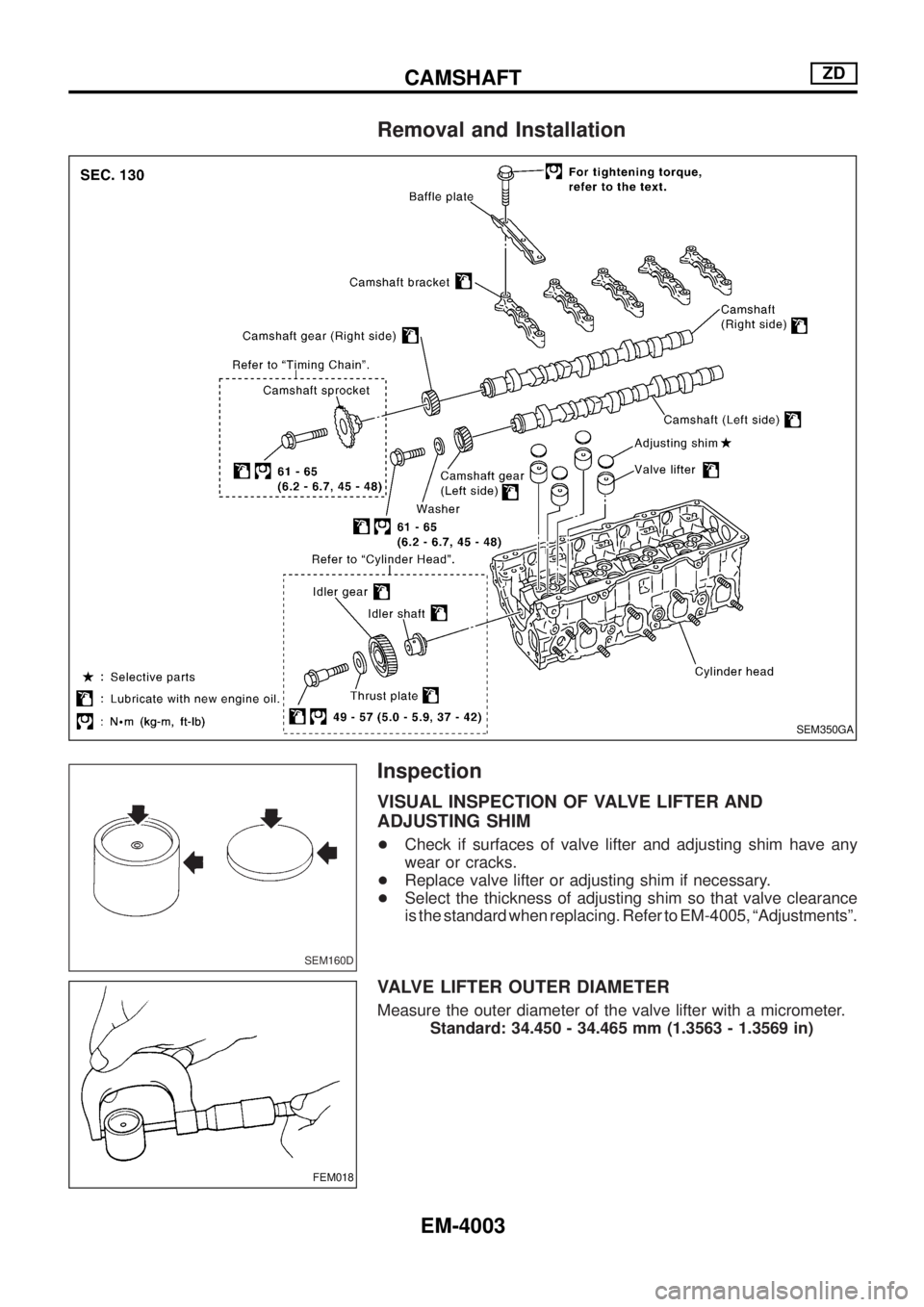
Removal and Installation
Inspection
VISUAL INSPECTION OF VALVE LIFTER AND
ADJUSTING SHIM
+Check if surfaces of valve lifter and adjusting shim have any
wear or cracks.
+Replace valve lifter or adjusting shim if necessary.
+Select the thickness of adjusting shim so that valve clearance
is the standard when replacing. Refer to EM-4005, ªAdjustmentsº.
VALVE LIFTER OUTER DIAMETER
Measure the outer diameter of the valve lifter with a micrometer.
Standard: 34.450 - 34.465 mm (1.3563 - 1.3569 in)
SEM350GA
SEM160D
FEM018
CAMSHAFTZD
EM-4003
Page 446 of 579
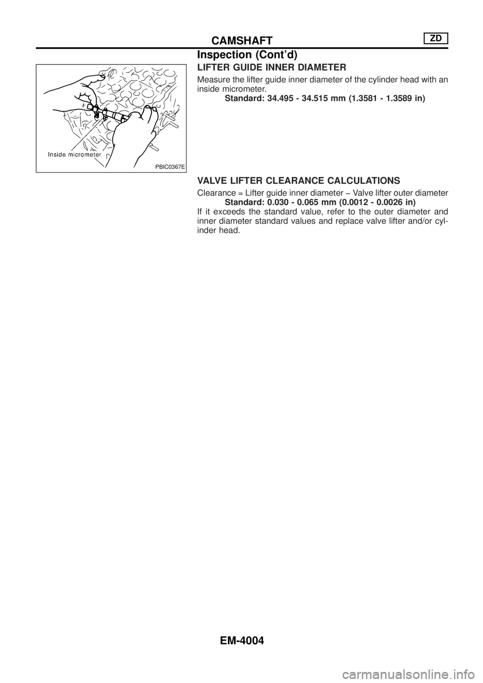
LIFTER GUIDE INNER DIAMETER
Measure the lifter guide inner diameter of the cylinder head with an
inside micrometer.
Standard: 34.495 - 34.515 mm (1.3581 - 1.3589 in)
VALVE LIFTER CLEARANCE CALCULATIONS
Clearance = Lifter guide inner diameter þ Valve lifter outer diameter
Standard: 0.030 - 0.065 mm (0.0012 - 0.0026 in)
If it exceeds the standard value, refer to the outer diameter and
inner diameter standard values and replace valve lifter and/or cyl-
inder head.
PBIC0367E
CAMSHAFTZD
Inspection (Cont'd)
EM-4004
Page 447 of 579
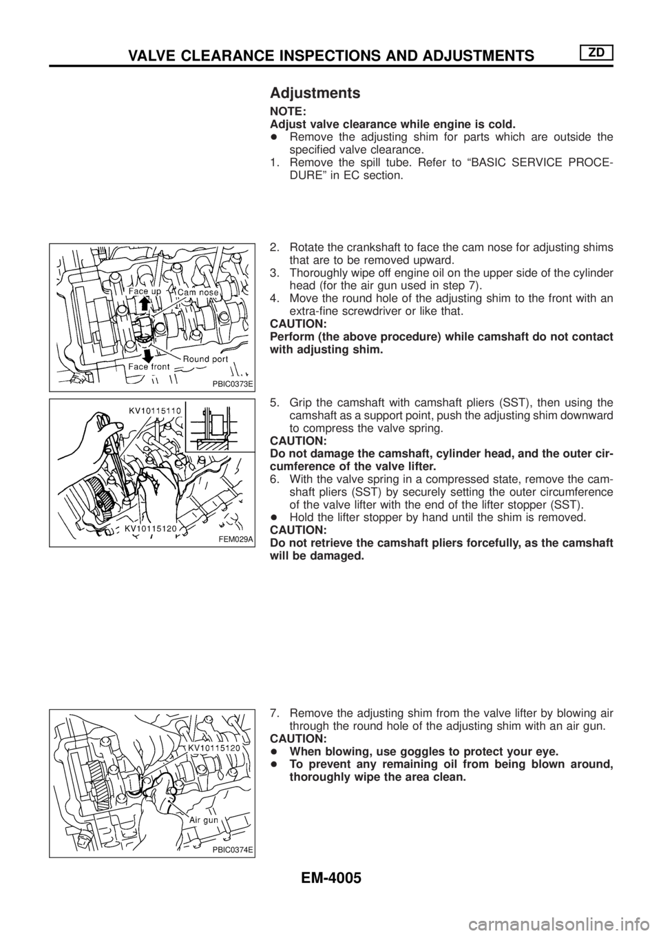
Adjustments
NOTE:
Adjust valve clearance while engine is cold.
+Remove the adjusting shim for parts which are outside the
speci®ed valve clearance.
1. Remove the spill tube. Refer to ªBASIC SERVICE PROCE-
DUREº in EC section.
2. Rotate the crankshaft to face the cam nose for adjusting shims
that are to be removed upward.
3. Thoroughly wipe off engine oil on the upper side of the cylinder
head (for the air gun used in step 7).
4. Move the round hole of the adjusting shim to the front with an
extra-®ne screwdriver or like that.
CAUTION:
Perform (the above procedure) while camshaft do not contact
with adjusting shim.
5. Grip the camshaft with camshaft pliers (SST), then using the
camshaft as a support point, push the adjusting shim downward
to compress the valve spring.
CAUTION:
Do not damage the camshaft, cylinder head, and the outer cir-
cumference of the valve lifter.
6. With the valve spring in a compressed state, remove the cam-
shaft pliers (SST) by securely setting the outer circumference
of the valve lifter with the end of the lifter stopper (SST).
+Hold the lifter stopper by hand until the shim is removed.
CAUTION:
Do not retrieve the camshaft pliers forcefully, as the camshaft
will be damaged.
7. Remove the adjusting shim from the valve lifter by blowing air
through the round hole of the adjusting shim with an air gun.
CAUTION:
+When blowing, use goggles to protect your eye.
+To prevent any remaining oil from being blown around,
thoroughly wipe the area clean.
PBIC0373E
FEM029A
PBIC0374E
VALVE CLEARANCE INSPECTIONS AND ADJUSTMENTSZD
EM-4005
Page 448 of 579
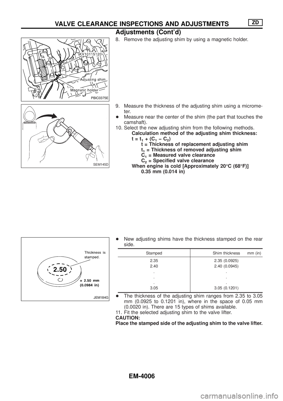
8. Remove the adjusting shim by using a magnetic holder.
9. Measure the thickness of the adjusting shim using a microme-
ter.
+Measure near the center of the shim (the part that touches the
camshaft).
10. Select the new adjusting shim from the following methods.
Calculation method of the adjusting shim thickness:
t=t
1+(C1þC2)
t = Thickness of replacement adjusting shim
t
1= Thickness of removed adjusting shim
C
1= Measured valve clearance
C
2= Speci®ed valve clearance
When engine is cold [Approximately 20ÉC (68ÉF)]
0.35 mm (0.014 in)
+New adjusting shims have the thickness stamped on the rear
side.
Stamped Shim thickness mm (in)
2.35
2.40
.
.
.
3.052.35 (0.0925)
2.40 (0.0945)
.
.
.
3.05 (0.1201)
+The thickness of the adjusting shim ranges from 2.35 to 3.05
mm (0.0925 to 0.1201 in), where in the space of 0.05 mm
(0.0020 in). There are 15 types of shims available.
11. Fit the selected adjusting shim to the valve lifter.
CAUTION:
Place the stamped side of the adjusting shim to the valve lifter.
PBIC0375E
SEM145D
JEM184G
VALVE CLEARANCE INSPECTIONS AND ADJUSTMENTSZD
Adjustments (Cont'd)
EM-4006
Page 449 of 579
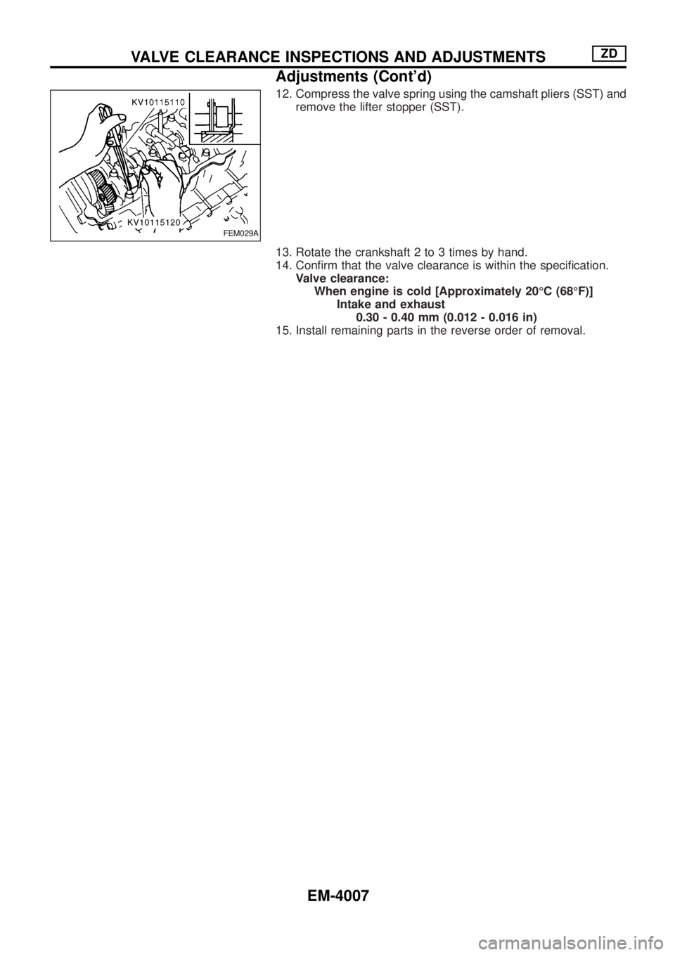
12. Compress the valve spring using the camshaft pliers (SST) and
remove the lifter stopper (SST).
13. Rotate the crankshaft 2 to 3 times by hand.
14. Con®rm that the valve clearance is within the speci®cation.
Valve clearance:
When engine is cold [Approximately 20ÉC (68ÉF)]
Intake and exhaust
0.30 - 0.40 mm (0.012 - 0.016 in)
15. Install remaining parts in the reverse order of removal.
FEM029A
VALVE CLEARANCE INSPECTIONS AND ADJUSTMENTSZD
Adjustments (Cont'd)
EM-4007
Page 450 of 579

Removal and Installation
2 idler gears are shown in this chapter. Idler gear (A) has scissors gear, and idler gear (B) does not.
SEM185HB
TIMING GEARZD
EM-4008